EP1213547A2 - Independent engine heater of a motor car - Google Patents
Independent engine heater of a motor car Download PDFInfo
- Publication number
- EP1213547A2 EP1213547A2 EP01125229A EP01125229A EP1213547A2 EP 1213547 A2 EP1213547 A2 EP 1213547A2 EP 01125229 A EP01125229 A EP 01125229A EP 01125229 A EP01125229 A EP 01125229A EP 1213547 A2 EP1213547 A2 EP 1213547A2
- Authority
- EP
- European Patent Office
- Prior art keywords
- housing part
- housing
- heater
- heater according
- axis
- Prior art date
- Legal status (The legal status is an assumption and is not a legal conclusion. Google has not performed a legal analysis and makes no representation as to the accuracy of the status listed.)
- Granted
Links
Images
Classifications
-
- B—PERFORMING OPERATIONS; TRANSPORTING
- B60—VEHICLES IN GENERAL
- B60H—ARRANGEMENTS OF HEATING, COOLING, VENTILATING OR OTHER AIR-TREATING DEVICES SPECIALLY ADAPTED FOR PASSENGER OR GOODS SPACES OF VEHICLES
- B60H1/00—Heating, cooling or ventilating [HVAC] devices
- B60H1/22—Heating, cooling or ventilating [HVAC] devices the heat being derived otherwise than from the propulsion plant
- B60H1/2203—Heating, cooling or ventilating [HVAC] devices the heat being derived otherwise than from the propulsion plant the heat being derived from burners
- B60H1/2209—Heating, cooling or ventilating [HVAC] devices the heat being derived otherwise than from the propulsion plant the heat being derived from burners arrangements of burners for heating an intermediate liquid
-
- F—MECHANICAL ENGINEERING; LIGHTING; HEATING; WEAPONS; BLASTING
- F24—HEATING; RANGES; VENTILATING
- F24H—FLUID HEATERS, e.g. WATER OR AIR HEATERS, HAVING HEAT-GENERATING MEANS, e.g. HEAT PUMPS, IN GENERAL
- F24H9/00—Details
- F24H9/02—Casings; Cover lids; Ornamental panels
-
- B—PERFORMING OPERATIONS; TRANSPORTING
- B60—VEHICLES IN GENERAL
- B60H—ARRANGEMENTS OF HEATING, COOLING, VENTILATING OR OTHER AIR-TREATING DEVICES SPECIALLY ADAPTED FOR PASSENGER OR GOODS SPACES OF VEHICLES
- B60H1/00—Heating, cooling or ventilating [HVAC] devices
- B60H1/22—Heating, cooling or ventilating [HVAC] devices the heat being derived otherwise than from the propulsion plant
- B60H2001/2268—Constructional features
- B60H2001/2278—Connectors, water supply, housing, mounting brackets
Definitions
- the invention relates to a motor-independently operable Heater of a motor vehicle, in particular in the form of a Auxiliary heater or an auxiliary heater, with the characteristics of Preamble of claim 1.
- Such a heater is for example from the WO 00/24600 known and has a housing in which a Burner and a heat exchanger coaxially enveloping the burner are accommodated.
- the housing is also with connection piece for the water or air flow and for the Water or air return equipped.
- the present invention addresses the problem an embodiment for a heater of the type mentioned to be specified in different installation space situations is relatively easy to assemble and a relatively simple one Cable routing enables.
- the invention is based on the general idea of the heater to divide into two device units that are assigned in Housing parts are housed, these housing parts assembled in different relative positions to each other to be able to reassemble for that Heater form a common housing.
- connection means with which the housing parts at least in two different, to each other around an axis of rotation rotated relative positions can be attached to each other are.
- the burner is on one housing part attached and arranged coaxially to the axis of rotation, while the heat exchanger is attached to the other housing part and is arranged coaxially to the axis of rotation. Because Brenner and Heat exchangers are generally rotationally symmetrical are the functional unit of burner and heat exchanger in any rotated relative position between the burner and the heat exchanger.
- the measure according to the invention enables connections or Connection groups on one and / or on the other Housing part are arranged by setting a suitable Relative position between the two housing parts depending on the existing installation conditions be positioned in a variety of ways. This can the heater according to the invention individually to each prevailing installation situation can be adjusted, which assembly and routing from and to the heater improved.
- the first housing part can have connecting pieces for fuel and / or fresh gas and / or exhaust gas.
- By a corresponding rotation adjustment of the first housing part can therefore be different for these connecting pieces Positions can be set.
- the second housing part can have connecting pieces for a flow and for a return of a heat transfer medium with which the heat exchanger is acted upon. By turning the second housing part can thus in this connector be positioned in different ways.
- a pumping device for the heat transfer medium be arranged on or in the second housing part next to the Heat exchanger.
- This also makes it a modular one Structure for this device unit achieved because the functional pump device interacting with the heat exchanger is arranged in or on the same housing part.
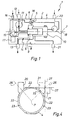
- connection means 5 are provided, which here with each housing part 3, 4 in the form of an internal, circumferential flange are formed. Screw connections 6, which are indicated by dash-dotted lines can for example by a cover, not shown here of the housing 2 are performed.
- the connection means 5 are designed so that the two housing parts 3 and 4 at least in two different relative positions are attachable, these relative positions by a rotation of the two housing parts 3, 4 relative to one another result about an axis of rotation 7. They are preferably at one another to be connected sides of the housing parts 3.4 so designed that when assembled housing 2 a closed outer contour results.
- This means in particular that the cross sections of the two housing parts 3, 4 at least in an area 8 in which the connection means 5 are arranged are, in all intended relative positions essentially lie congruently on top of each other.
- the first housing part 3 contains a burner 9 on the first Fixed housing part 3 and arranged coaxially to the axis of rotation 7 is.
- the burner 9 stands in the axial direction of the first housing part 3 and protrudes when assembled Housing 2 in a heat exchanger or heat exchanger 10 one, which is housed in the second housing part 4.
- the Heat exchanger 10 is attached to the second housing part 4 and also aligned coaxially to the axis of rotation 7.
- the first housing part 3 contains the one shown here special embodiment also a blower 11, the Burner 9 supplies fresh gas and thereby at the same time from Burner 9 discharges exhaust gas generated from burner 9.
- the first housing part 3 has a supply of fresh gas Fresh gas connecting piece 12; for the removal of exhaust gas a corresponding exhaust connection piece 13 is provided.
- the Coupling between burner 9 and heat exchanger 10 takes place with the housing 2 assembled so that the ones produced by the burner 9 exhaust gases are called the heat exchanger in the usual way 10 can act, the cooled exhaust gases from an exhaust line 14 can be detected in the first housing part 3 is housed.
- the corresponding connections and Connections are preferably designed so that they are in each of the adjustable relative positions between the housing parts 3 and 4 are sufficiently gas-tight.
- the first housing part 3 also contains a fuel metering device 15, which have a fuel connector 16 to a fuel supply of a motor vehicle is connected, in which the heater 1 is installed is.
- the fuel metering device 15 supplies the Burner 9 with the required amount of fuel.
- a control unit 17 housed the burner via appropriate lines 9 or a glow plug, not shown, the fuel metering device 15 and the blower 11 actuated.
- the control unit 17 via a corresponding interface 18 also operates a pump 19 in the second housing part 4 is housed and to act on the heat exchanger 10 serves with a heat transfer medium.
- This Pump 19 is on the suction side with a return connection piece 20 and pressure side with an input of Heat exchanger 10 connected. An output of the heat exchanger 10 is connected to a flow connector 21. Via the return connection piece arranged on the second housing part 4 20 and flow connector 21 is the Heat exchanger 10 integrated in a fluid circuit of the vehicle, such that the heater 1 can be operated independently of the engine and serves as an auxiliary heater or as an auxiliary heater. at pure heating can also be dispensed with the pump 19.
- the Pump 19 can also be modular on the outside of housing 2 be mounted.
- the coolant of an engine cooling circuit so that the heater 1 is a water heater forms.
- the one charged with the coolant or "cooling water” Heat exchanger 10 envelops the burner 9 and forms thereby a so-called “water jacket”.
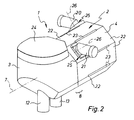
- the housing parts 3, 4 have at least in area 8 of the adjoining pages a regular octagonal outer cross-section. While in the case of the first housing part 3, the octagonal outer cross section is only formed in the area of the connection means 5, has the second housing part 4 along its entire length axial extension the octagonal outer cross section. Accordingly has the outer contour of the second housing part 4 eight flat outer surfaces 22, with adjacent outer surfaces 22 each inclined at 45 ° to each other. Between two adjacent outer surfaces 22 are virtually in the Edges of the outer cross section grooves 23 formed here have no undercut. Embodiments are likewise possible in which the grooves 23 have an undercut. The grooves 23 serve as points of attack for fasteners, with which the heater 1 can be attached to the vehicle is.
- the second housing part 2 has the first housing part 3 on one side, in Fig. 2 above, a lid 24. On one the side opposite the cover 24, in FIG. 2 below, the first housing part 3 has the fresh gas connecting piece 12 and the exhaust port 13. The associated one Fuel connector 16 is not visible here.
- the second housing part 2 has two different outer surfaces 22 on the one hand the return connection piece 20 and other the flow connector 21.
- the connecting pieces 20, 21 of the second housing part 4 are here in each case by means of a holding device 25 on the second housing part 2 fixed, which allows an adjustment of the connecting piece 20,21. 2 and 3 is an embodiment shown, in which the connecting piece 20.21 in 90 ° steps each with respect to an associated pivot axis 26 are removable. This pivot axis 26 is perpendicular on the axis of rotation 7.
- FIG. 2 is between the housing parts 3 and 4 set a first relative position at which the cover 24 above and the connecting piece 12 and 13th of the first housing part 3 are arranged below.
- the connecting pieces 20, 21 of the second housing part 4 are shown in FIG. 2 oriented so that they are parallel to each other and perpendicular run to the axis of rotation 7.
- the return connector 20 directed backwards, while the flow connector 21 is directed forward.
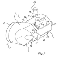
- FIG. 3 shows a second one Relative position between the two housing parts 3 and 4, in which the two housing parts 3 and 4 about the axis of rotation 7 are rotated 90 ° against each other. Accordingly, here the lid 24 arranged at the rear while the connecting piece 12 and 13 of the first housing part 3 are in the front.
- the connecting pieces 20 and 21 of the second housing part 4 repositioned such that both after point upwards or protrude upwards. Thereby extend the two connecting pieces 20, 21 again perpendicular to the axis of rotation 7 and parallel to each other. The connecting piece 20 and 21 are therefore repositioned by 180 ° in FIG. 3 compared to FIG. 2.
- FIG. 4 are the connecting piece 20,21 of the second Housing part 4 preferably angled at about 45 ° and dimensioned so that the respective connecting piece 20.21 in two pivoted by 180 ° with respect to the associated pivot axis 26 Positions is always arranged so that one of second housing part 4 facing away section of the outer contour of the respective connection piece 20, 21 in a level 27 lies or extends in a plane 27 in which one of the Outer surfaces 22 is located adjacent to that outer surface 22 is at which the respective connection piece 20,21 is arranged.
- Fig. 4 are for the flow connector 21 reproduced these two positions, one with solid lines and the other with broken lines is shown.
Abstract
Description
Die Erfindung betrifft ein motorunabhängig betreibbares Heizgerät eines Kraftfahrzeuges, insbesondere in Form eines Zuheizers oder einer Standheizung, mit den Merkmalen des Oberbegriffs des Anspruchs 1.The invention relates to a motor-independently operable Heater of a motor vehicle, in particular in the form of a Auxiliary heater or an auxiliary heater, with the characteristics of Preamble of claim 1.
Ein derartiges Heizgerät ist beispielsweise aus der WO 00/24600 bekannt und besitzt ein Gehäuse, in dem ein Brenner sowie ein den Brenner koaxial umhüllender Wärmeübertrager untergebracht sind. Das Gehäuse ist außerdem mit Anschlußstutzen für den Wasser- bzw. Luft-Vorlauf und für den Wasser- bzw. Luft-Rücklauf ausgestattet. Um eine einfache, individuelle, wenig Bauraum benötigende Leitungsführung beim Einbau des Heizgerätes in ein Kraftfahrzeug zu ermöglichen, ist wenigstens einer der Anschlußstutzen als verdrehbarer Winkelstutzen ausgebildet. Dennoch kann es auch hier zu Einbausituationen kommen, bei denen die Montage sowie die Leitungsführung relativ aufwendig sind.Such a heater is for example from the WO 00/24600 known and has a housing in which a Burner and a heat exchanger coaxially enveloping the burner are accommodated. The housing is also with connection piece for the water or air flow and for the Water or air return equipped. To be a simple, individual cable routing that requires little installation space Enable installation of the heater in a motor vehicle, is at least one of the connecting pieces as rotatable Elbow connector designed. Nevertheless, installation situations can also occur here come where the assembly as well as the wiring are relatively expensive.
Die vorliegende Erfindung beschäftigt sich mit dem Problem, für ein Heizgerät der eingangs genannten Art eine Ausführungsform anzugeben, die bei unterschiedlichen Bauraumsituationen relativ leicht montierbar ist und eine relativ einfache Leitungsführung ermöglicht.The present invention addresses the problem an embodiment for a heater of the type mentioned to be specified in different installation space situations is relatively easy to assemble and a relatively simple one Cable routing enables.
Dieses Problem wird erfindungsgemäß durch ein Heizgerät mit den Merkmalen des Anspruchs 1 gelöst.According to the invention, this problem is solved by a heater solved the features of claim 1.
Die Erfindung beruht auf dem allgemeinen Gedanken, das Heizgerät in zwei Geräteeinheiten zu unterteilen, die in zugeordneten Gehäuseteilen untergebracht sind, wobei diese Gehäuseteile in unterschiedlichen Relativlagen zueinander zusammengebaut werden können, um für das so wieder zusammengefügte Heizgerät ein gemeinsames Gehäuse auszubilden. Zu diesem Zweck sind Anschlußmittel vorgesehen, mit denen die Gehäuseteile zumindest in zwei verschiedenen, zueinander um eine Drehachse verdrehte Relativpositionen aneinander befestigbar sind. Des weiteren ist der Brenner an dem einen Gehäuseteil befestigt und koaxial zur Drehachse angeordnet, während der Wärmeübertrager am anderen Gehäuseteil befestigt und koaxial zur Drehachse angeordnet ist. Da Brenner und Wärmeübertrager in der Regel rotationssymmetrisch ausgebildet sind, kann die funktionale Einheit aus Brenner und Wärmeübertrager in jeder beliebigen gedrehten Relativstellung zwischen Brenner und Wärmeübertrager gewährleistet werden.The invention is based on the general idea of the heater to divide into two device units that are assigned in Housing parts are housed, these housing parts assembled in different relative positions to each other to be able to reassemble for that Heater form a common housing. To this Purpose are provided connection means with which the housing parts at least in two different, to each other around an axis of rotation rotated relative positions can be attached to each other are. Furthermore, the burner is on one housing part attached and arranged coaxially to the axis of rotation, while the heat exchanger is attached to the other housing part and is arranged coaxially to the axis of rotation. Because Brenner and Heat exchangers are generally rotationally symmetrical are the functional unit of burner and heat exchanger in any rotated relative position between the burner and the heat exchanger.
Durch die erfindungsgemäße Maßnahme können Anschlüsse bzw. Anschlußgruppen, die an dem einen und/oder an dem anderen Gehäuseteil angeordnet sind, durch die Einstellung einer geeigneten Relativposition zwischen den beiden Gehäuseteilen in Abhängigkeit der jeweils vorliegenden Einbauverhältnisse auf vielfältige Weise positioniert werden. Hierdurch kann das erfindungsgemäße Heizgerät individuell an die jeweils herrschende Einbausituation angepaßt werden, wodurch sich die Montage sowie die Leitungsführung vom und zum Heizgerät verbessert.The measure according to the invention enables connections or Connection groups on one and / or on the other Housing part are arranged by setting a suitable Relative position between the two housing parts depending on the existing installation conditions be positioned in a variety of ways. This can the heater according to the invention individually to each prevailing installation situation can be adjusted, which assembly and routing from and to the heater improved.
Durch die Unterteilung des Heizgerätes in zwei Geräteeinheiten, ergibt sich die Möglichkeit, diese Geräteeinheiten modulartig auszubilden, so daß jeweils mehrere zusammengehörige Komponenten in einem der Gehäuseteile zusammengefaßt sind. Insbesondere kann das erste Gehäuseteil Anschlußstutzen für Brennstoff und/oder Frischgas und/oder Abgas aufweisen. Durch eine entsprechende Drehverstellung des ersten Gehäuseteils können somit für diese Anschlußstutzen verschiedene Positionen eingestellt werden.By dividing the heater into two units, there is the possibility of these device units modular train, so that several belong together Components summarized in one of the housing parts are. In particular, the first housing part can have connecting pieces for fuel and / or fresh gas and / or exhaust gas. By a corresponding rotation adjustment of the first housing part can therefore be different for these connecting pieces Positions can be set.
Im ersten Gehäuseteil sind neben dem Brenner vorzugsweise ein Steuergerät und/oder eine Brennstoffdosiereinrichtung und/oder ein zur Zuführung von Frischgas und/oder zur Abführung von Abgas dienendes Gebläse untergebracht. Hierdurch wird im ersten Gehäuseteil eine Geräteeinheit ausgebildet, deren Komponenten funktionell mit dem Brenner zusammenwirken.In the first housing part, in addition to the burner, are preferred a control unit and / or a fuel metering device and / or one for the supply of fresh gas and / or for the discharge exhaust fan used. hereby a device unit is formed in the first housing part, whose components functionally interact with the burner.
Im Unterschied dazu kann das zweite Gehäuseteil Anschlußstutzen für einen Vorlauf und für einen Rücklauf eines Wärmeübertragungsmediums aufweisen, mit dem der Wärmeübertrager beaufschlagt ist. Durch eine entsprechende Verdrehung des zweiten Gehäuseteils können somit diese Anschlußstutzen in unterschiedlicher Weise positioniert werden.In contrast to this, the second housing part can have connecting pieces for a flow and for a return of a heat transfer medium with which the heat exchanger is acted upon. By turning the second housing part can thus in this connector be positioned in different ways.
Zweckmäßig kann am oder im zweiten Gehäuseteil neben dem Wärmeübertrager eine Pumpeinrichtung für das Wärmeübertragungsmedium angeordnet sein. Auch hierdurch wird ein modularer Aufbau für diese Geräteeinheit erreicht, da die funktionell mit dem Wärmeübertrager zusammenwirkende Pumpeinrichtung im oder am gleichen Gehäuseteil angeordnet ist.Appropriately, on or in the second housing part next to the Heat exchanger a pumping device for the heat transfer medium be arranged. This also makes it a modular one Structure for this device unit achieved because the functional pump device interacting with the heat exchanger is arranged in or on the same housing part.
Weitere wichtige Merkmale und Vorteile der erfindungsgemäßen Vorrichtung ergeben sich aus den Unteransprüchen, aus den Zeichnungen und aus der zugehörigen Figurenbeschreibung anhand der Zeichnungen.Other important features and advantages of the invention Device result from the dependent claims, from the Drawings and from the associated figure description based on of the drawings.
Es versteht sich, daß die vorstehend genannten und die nachstehend noch zu erläuternden Merkmale nicht nur in der jeweils angegebenen Kombination, sondern auch in anderen Kombinationen oder in Alleinstellung verwendbar sind, ohne den Rahmen der vorliegenden Erfindung zu verlassen.It is understood that the above and those below Features to be explained not only in each case specified combination, but also in other combinations or can be used alone without the To leave the scope of the present invention.
Ein bevorzugtes Ausführungsbeispiel der Erfindung ist in den Zeichnungen dargestellt und wird in der nachfolgenden Beschreibung näher erläutert.A preferred embodiment of the invention is in the Drawings are shown in the description below explained in more detail.
Es zeigen, jeweils schematisch,
- Fig. 1
- einen Längsschnitt durch eine Prinzipdarstellung eines erfindungsgemäßen Heizgerätes,
- Fig. 2
- eine perspektivische Ansicht auf das Heizgerät nach der Erfindung bei einer ersten Zusammenbaukonfiguration,
- Fig. 3
- eine perspektivische Ansicht wie in Fig. 2, jedoch bei einer zweiten Zusammenbaukonfiguration, und
- Fig. 4
- einen Querschnitt durch ein Gehäuseteil des erfindungsgemäßen Heizgerätes.
- Fig. 1
- 2 shows a longitudinal section through a basic illustration of a heating device according to the invention,
- Fig. 2
- 2 shows a perspective view of the heating device according to the invention in a first assembly configuration,
- Fig. 3
- a perspective view as in Fig. 2, but in a second assembly configuration, and
- Fig. 4
- a cross section through a housing part of the heater according to the invention.
Entsprechend Fig. 1 weist ein erfindungsgemäßes Heizgerät 1
ein zweiteiliges Gehäuse 2 auf, das aus einem ersten Gehäuseteil
3 und aus einem zweiten Gehäuseteil 4 zusammengebaut
ist. Zu diesem Zweck sind Anschlußmittel 5 vorgesehen, die
hier bei jedem Gehäuseteil 3,4 in Form eines innenliegenden,
umlaufenden Flansches ausgebildet sind. Verschraubungen 6,
die durch strichpunktierte Linien angedeutet sind, können
beispielsweise durch einen hier nicht dargestellten Deckel
des Gehäuses 2 durchgeführt werden. Die Anschlußmittel 5
sind so gestaltet, daß die beiden Gehäuseteile 3 und 4 wenigstens
in zwei verschiedenen Relativpositionen aneinander
befestigbar sind, wobei sich diese Relativpositionen durch
eine Verdrehung der beiden Gehäuseteile 3,4 relativ zueinander
um eine Drehachse 7 ergeben. Vorzugsweise sind die aneinander
anzuschließenden Seiten der Gehäuseteile 3,4 so
ausgestaltet, daß sich bei zusammengebautem Gehäuse 2 eine
geschlossene Außenkontur ergibt. Das bedeutet insbesondere,
daß die Querschnitte der beiden Gehäuseteile 3,4 zumindest
in einem Bereich 8, in dem die Anschlußmittel 5 angeordnet
sind, in allen vorgesehenen Relativpositionen im wesentlichen
deckungsgleich aufeinanderliegen.1 shows a heater 1 according to the invention
a two-
Das erste Gehäuseteil 3 enthält einen Brenner 9, der am ersten
Gehäuseteil 3 befestigt und koaxial zur Drehachse 7 angeordnet
ist. Der Brenner 9 steht in axialer Richtung von
dem ersten Gehäuseteil 3 ab und ragt bei zusammengebautem
Gehäuse 2 in einen Wärmetauscher oder Wärmeübertrager 10
ein, der im zweiten Gehäuseteil 4 untergebracht ist. Der
Wärmeübertrager 10 ist am zweiten Gehäuseteil 4 befestigt
und ebenfalls koaxial zur Drehachse 7 ausgerichtet. Durch
die gewählte koaxiale Positionierung von Brenner 9 und Wärmeübertrager
10 kann auch bei verschiedenen Relativpositionen
zwischen den beiden Gehäuseteilen 3 und 4 die gewünschte
funktionale Kopplung zwischen Brenner 9 und Wärmeübertrager
10 gewährleistet werden.The
Das erste Gehäuseteil 3 enthält bei der hier dargestellten
besonderen Ausführungsform außerdem ein Gebläse 11, das dem
Brenner 9 Frischgas zuführt und dadurch gleichzeitig vom
Brenner 9 erzeugtes Abgas aus dem Brenner 9 abführt. Für die
Zufuhr von Frischgas besitzt das erste Gehäuseteil 3 einen
Frischgas-Anschlußstutzen 12; für die Abfuhr von Abgas ist
ein entsprechender Abgas-Anschlußstutzen 13 vorgesehen. Die
Kopplung zwischen Brenner 9 und Wärmeübertrager 10 erfolgt
bei zusammengebautem Gehäuse 2 so, daß die vom Brenner 9 erzeugten
heißen Abgase in üblicher Weise den Wärmeübertrager
10 beaufschlagen können, wobei die abgekühlten Abgase von
einem Abgasstrang 14 erfaßt werden, der im ersten Gehäuseteil
3 untergebracht ist. Die entsprechenden Anschlüsse und
Verbindungen sind vorzugsweise so ausgebildet, daß sie in
jeder der einstellbaren Relativpositionen zwischen den Gehäuseteilen
3 und 4 hinreichend gasdicht sind.The
Das erste Gehäuseteil 3 enthält außerdem eine Brennstoffdosiereinrichtung
15, die über einen Brennstoff-Anschlußstutzen
16 an eine Brennstoffversorgung eines Kraftfahrzeugs
angeschlossen ist, in welches das Heizgerät 1 eingebaut
ist. Die Brennstoffdosiereinrichtung 15 versorgt den
Brenner 9 mit der erforderlichen Brennstoffmenge. Im ersten
Gehäuseteil 3 ist zweckmäßigerweise auch ein Steuergerät 17
untergebracht, das über entsprechende Leitungen den Brenner
9 bzw. einen nicht dargestellten Glühstift, die Brennstoffdosiereinrichtung
15 und das Gebläse 11 betätigt. Des weiteren
ist bei der hier gezeigten Ausführungsform vorgesehen,
daß das Steuergerät 17 über eine entsprechende Schnittstelle
18 außerdem eine Pumpe 19 betätigt, die im zweiten Gehäuseteil
4 untergebracht ist und zur Beaufschlagung des Wärmeübertragers
10 mit einem Wärmeübertragungsmedium dient. Diese
Pumpe 19 ist saugseitig mit einem Rücklauf-Anschlußstutzen
20 und druckseitig mit einem Eingang des
Wärmeübertragers 10 verbunden. Ein Ausgang des Wärmeübertragers
10 ist mit einem Vorlauf-Anschlußstutzen 21 verbunden.
Über die am zweiten Gehäuseteil 4 angeordneten Rücklauf-Anschlußstutzen
20 und Vorlauf-Anschlußstutzen 21 ist der
Wärmeübertrager 10 in einen Fluidkreis des Fahrzeuges eingebunden,
derart, daß das Heizgerät 1 motorunabhängig betreibbar
ist und als Zuheizer oder als Standheizung dient. Bei
einer reinen Zuheizung kann die Pumpe 19 auch entfallen. Die
Pumpe 19 kann auch modular an der Außenseite des Gehäuses 2
montiert sein.The
Beim Wärmeübertragungsmedium, das vom Wärmeübertrager 10 erwärmt
wird, handelt es sich hier um das Kühlmittel eines Motorkühlkreises,
so daß das Heizgerät 1 ein Wasserheizgerät
bildet. Der mit dem Kühlmittel oder "Kühlwasser" beaufschlagte
Wärmeübertrager 10 umhüllt den Brenner 9 und bildet
dadurch einen sogenannten "Wassermantel".In the heat transfer medium that is heated by the
Entsprechend den Fig. 2 bis 4 besitzen die Gehäuseteile 3,4
zumindest im Bereich 8 der aneinander anschließenden Seiten
einen regelmäßigen achteckigen Außenquerschnitt. Während
beim ersten Gehäuseteil 3 hier der achteckige Außenquerschnitt
nur im Bereich der Anschlußmittel 5 ausgebildet ist,
besitzt das zweite Gehäuseteil 4 entlang seiner gesamten
axialen Erstreckung den achteckigen Außenquerschnitt. Dementsprechend
weist die Außenkontur des zweiten Gehäuseteils
4 acht ebene Außenflächen 22 auf, wobei benachbarte Außenflächen
22 jeweils um 45° zueinander geneigt verlaufen. Zwischen
zwei benachbarten Außenflächen 22 sind quasi in den
Kanten des Außenquerschnitts Rillen 23 ausgebildet, die hier
keinen Hinterschnitt aufweisen. Ebenso sind Ausführungsformen
möglich, bei denen die Rillen 23 einen Hinterschnitt besitzen.
Die Rillen 23 dienen als Angriffsstellen für Befestigungsmittel,
mit denen das Heizgerät 1 am Fahrzeug befestigbar
ist. 2 to 4, the
Entsprechend den Fig. 2 und 3 besitzt das erste Gehäuseteil
3 an einer Seite, in Fig. 2 oben, einen Deckel 24. An einer
dem Deckel 24 gegenüberliegenden Seite, in Fig. 2 unten,
weist das erste Gehäuseteil 3 den Frischgas-Anschlußstutzen
12 und den Abgas-Anschlußstutzen 13 auf. Der zugehörige
Brennstoff-Anschlußstutzen 16 ist hier nicht sichtbar. Das
zweite Gehäuseteil 2 weist an zwei verschiedenen Außenflächen
22 zum einen den Rücklauf-Anschlußstutzen 20 und zum
anderen den Vorlauf-Anschlußstutzen 21 auf. Die Anschlußstutzen
20,21 des zweiten Gehäuseteils 4 sind hier jeweils
mittels einer Halteeinrichtung 25 am zweiten Gehäuseteil 2
fixiert, die eine Verstellung der Anschlußstutzen 20,21 ermöglicht.
In den Fig. 2 und 3 ist dabei eine Ausführungsform
dargestellt, bei der die Anschlußstutzen 20,21 in 90°-Schritten
jeweils bezüglich einer zugehörigen Schwenkachse
26 umsteckbar sind. Diese Schwenkachse 26 steht dabei senkrecht
auf der Drehachse 7. Des weiteren sind der Rücklauf-Anschlußstutzen
20 und der Vorlauf-Anschlußstutzen 21 abgewinkelt,
hier um etwa 45°.2 and 3 has the
Bei der Konstellation gemäß Fig. 2 ist zwischen den Gehäuseteilen
3 und 4 eine erste Relativposition eingestellt, bei
welcher der Deckel 24 oben und die Anschlußstutzen 12 und 13
des ersten Gehäuseteils 3 unten angeordnet sind. Die Anschlußstutzen
20,21 des zweiten Gehäuseteils 4 sind in Fig.
2 so orientiert, daß die parallel zueinander und senkrecht
zur Drehachse 7 verlaufen. Dabei ist der Rücklauf-Anschlußstutzen
20 nach hinten gerichtet, während der Vorlauf-Anschlußstutzen
21 nach vorn gerichtet ist. Im Unterschied
dazu zeigt die Konstellation gemäß Fig. 3 eine zweite
Relativposition zwischen den beiden Gehäuseteilen 3 und 4,
bei der die beiden Gehäuseteile 3 und 4 um die Drehachse 7
um 90° gegeneinander verdreht sind. Dementsprechend ist hier
der Deckel 24 hinten angeordnet, während sich die Anschlußstutzen
12 und 13 des ersten Gehäuseteils 3 vorn befinden.
In Fig. 3 sind zusätzlich die Anschlußstutzen 20 und 21 des
zweiten Gehäuseteils 4 umgesteckt, derart, daß beide nach
oben weisen bzw. nach oben abstehen. Dabei erstrecken sich
die beiden Anschlußstutzen 20,21 wieder senkrecht zur Drehachse
7 und parallel zueinander. Die Anschlußstutzen 20 und
21 sind in Fig. 3 gegenüber Fig. 2 demnach um 180° umgesteckt.2 is between the
Neben den in den Fig. 2 und 3 gezeigten Konfigurationen für
den Zusammenbau des Heizgerätes 1 sind noch weitere Konfiguationen
mit anderen Relativpositionen zwischen den beiden
Gehäuseteilen 3 und 4 möglich. Dementsprechend kann das erfindungsgemäße
Heizgerät 1 an viele verschiedene Einbausituationen
individuell angepaßt werden.In addition to the configurations shown in FIGS. 2 and 3 for
the assembly of the heater 1 are still further configurations
with other relative positions between the two
Entsprechend Fig. 4 sind die Anschlußstutzen 20,21 des zweiten
Gehäuseteils 4 vorzugsweise um etwa 45° abgewinkelt und
so dimensioniert, daß der jeweilige Anschlußstutzen 20,21 in
zwei, bezüglich der zugehörigen Schwenkachse 26 um 180° verschwenkte
Stellungen stets so angeordnet ist, daß ein vom
zweiten Gehäuseteil 4 abgewandter Abschnitt der Außenkontur
des jeweiligen Anschlußstutzens 20,21 in einer Ebene 27
liegt bzw. sich in einer Ebene 27 erstreckt, in der eine der
Außenflächen 22 liegt, die zu derjenigen Außenfläche 22 benachbart
ist, an welcher der jeweilige Anschlußstutzen 20,21
angeordnet ist. In Fig. 4 sind für den Vorlauf-Anschlußstutzen
21 diese beiden Positionen wiedergegeben,
wobei die eine mit durchgezogenen Linien und die andere mit
unterbrochenen Linien dargestellt ist.4 are the connecting
Durch diese Bauweise ergibt sich für das zweite Gehäuseteil 4 ein reduzierter Raumbedarf. This construction results for the second housing part 4 a reduced space requirement.
- 11
- Vorrichtungcontraption
- 22
- Gehäusecasing
- 33
- erstes Gehäuseteilfirst housing part
- 44
- zweites Gehäuseteilsecond housing part
- 55
- Anschlußmittelconnection means
- 66
- Verschraubungscrew
- 77
- Drehachseaxis of rotation
- 88th
- BereichArea
- 99
- Brennerburner
- 1010
- WärmeübertragerHeat exchanger
- 1111
- Gebläsefan
- 1212
- Frischgas-AnschlußstutzenFresh gas pipe connection
- 1313
- Abgas-AnschlußstutzenExhaust pipe connection
- 1414
- Abgastraktexhaust tract
- 1515
- Brennstoffdosiereinrichtungfuel dosing
- 1616
- Brennstoff-AnschlußstutzenFuel connecting branch
- 1717
- Steuergerätcontrol unit
- 1818
- Schnittstelleinterface
- 1919
- Pumpepump
- 2020
- Rücklauf-AnschlußstutzenReturn pipe connection
- 2121
- Vorlauf-AnschlußstutzenFlow connection piece
- 2222
- Außenflächenexterior surfaces
- 2323
- Rille groove
- 2424
- Deckelcover
- 2525
- Halteeinrichtungholder
- 2626
- Schwenkachseswivel axis
- 2727
- Ebenelevel
Claims (13)
dadurch gekennzeichnet, daß das Gehäuse (2) aus einem ersten Gehäuseteil (3) und aus einem zweiten Gehäuseteil (4) zusammengebaut ist, wobei Anschlußmittel (5), mit denen die Gehäuseteile (3,4) aneinander befestigt sind, so gestaltet sind, daß die beiden Gehäuseteile (3,4) zumindest in zwei verschiedenen, zueinander um eine Drehachse (7) verdrehte Relativpositionen aneinander befestigbar sind, wobei der Brenner (9) am ersten Gehäuseteil (3) befestigt und koaxial zur Drehachse (7) angeordnet ist und wobei der Wärmeübertrager (10) am zweiten Gehäuseteil (4) befestigt und koaxial zur Drehachse (7) angeordnet ist.Motor-operated heater of a motor vehicle, in particular in the form of an auxiliary heater or auxiliary heater, with a housing (2) in which a burner (9) and a heat exchanger (10) coaxially enveloping the burner (9) are accommodated,
characterized in that the housing (2) is assembled from a first housing part (3) and from a second housing part (4), connection means (5) with which the housing parts (3, 4) are fastened to one another are designed in such a way that that the two housing parts (3, 4) can be fastened to one another in at least two different relative positions rotated relative to one another about an axis of rotation (7), the burner (9) being fastened to the first housing part (3) and arranged coaxially to the axis of rotation (7) and wherein the heat exchanger (10) is attached to the second housing part (4) and is arranged coaxially to the axis of rotation (7).
dadurch gekennzeichnet, daß das erste Gehäuseteil (3) Anschlußstutzen (12,13,16) für Brennstoff und/oder Frischgas und/oder Abgas aufweist. Heater according to claim 1,
characterized in that the first housing part (3) has connecting pieces (12, 13, 16) for fuel and / or fresh gas and / or exhaust gas.
dadurch gekennzeichnet, daß im ersten Gehäuseteil (3) ein Steuergerät (17) und/oder eine Brennstoffdosiereinrichtung (15) und/oder ein zur Zuführung von Frischgas und/oder zur Abführung von Abgas dienendes Gebläse (11) untergebracht ist.Heater according to claim 1 or 2,
characterized in that a control device (17) and / or a fuel metering device (15) and / or a blower (11) serving for the supply of fresh gas and / or the removal of exhaust gas is accommodated in the first housing part (3).
dadurch gekennzeichnet, daß das zweite Gehäuseteil (4) Anschlußstutzen (20,21) für einen Vorlauf und einen Rücklauf eines Wärmeübertragungsmediums aufweist, mit dem der Wärmeübertrager (10) beaufschlagt ist.Heater according to one of claims 1 to 3,
characterized in that the second housing part (4) has connecting pieces (20, 21) for a flow and a return of a heat transfer medium with which the heat exchanger (10) is acted upon.
dadurch gekennzeichnet, daß am oder im zweiten Gehäuseteil (4) eine Pumpeinrichtung (19) für das Wärmeübertragungsmedium angeordnet ist.Heater according to one of claims 1 to 4,
characterized in that a pump device (19) for the heat transfer medium is arranged on or in the second housing part (4).
dadurch gekennzeichnet, daß die Gehäuseteile (3,4) zumindest im Bereich (8) der aneinander anschließenden Seiten jeweils einen regelmäßigen, achteckigen Außenquerschnitt aufweisen.Heater according to one of claims 1 to 5,
characterized in that the housing parts (3, 4) each have a regular, octagonal outer cross-section, at least in the area (8) of the adjoining sides.
dadurch gekennzeichnet, daß zumindest einer der Anschlußstutzen (20,21) an einem ebenen Abschnitt (22) der Außenkontur des jeweiligen Gehäuseteils (4) angeordnet ist.Heater at least according to claim 2 or 4,
characterized in that at least one of the connecting pieces (20, 21) is arranged on a flat section (22) of the outer contour of the respective housing part (4).
dadurch gekennzeichnet, daß der ebene Abschnitt durch eine der acht Außenflächen (22) des jeweiligen Gehäuseteils (4) gebildet ist.Heater according to claims 6 and 7,
characterized in that the flat section is formed by one of the eight outer surfaces (22) of the respective housing part (4).
dadurch gekennzeichnet, daß zumindest einer der Anschlußstutzen (20,21) um eine senkrecht auf der Drehachse (7) stehende Schwenkachse (26) verstellbar ist.Heater at least according to claim 2 or 4,
characterized in that at least one of the connecting pieces (20, 21) can be adjusted about a pivot axis (26) perpendicular to the axis of rotation (7).
dadurch gekennzeichnet, daß der verstellbare Anschlußstutzen (20,21) in wenigstens zwei Positionen verstellbar ist, die relativ zueinander um 180° verschwenkt sind, wobei der den Anschlußstutzen (20,21) aufweisenden Außenfläche (22) in Umfangsrichtung des jeweiligen Gehäuseteils (4) an jeder Seite eine weitere Außenfläche (22) benachbart ist, die in einer Ebene (27) liegt, wobei der Anschlußstutzen (20,21) in jeder dieser Positionen in einer dieser Ebenen (27) oder auf einer dem jeweiligen Gehäuseteil (4) zugewandten Seite dieser Ebene (27) angeordnet ist.Heater according to claims 8 and 9,
characterized in that the adjustable connecting piece (20, 21) is adjustable in at least two positions which are pivoted through 180 ° relative to one another, the outer surface (22) having the connecting piece (20, 21) in the circumferential direction of the respective housing part (4) On each side there is a further outer surface (22) which lies in a plane (27), the connecting piece (20, 21) in each of these positions in one of these planes (27) or on a respective part of the housing (4) Side of this level (27) is arranged.
dadurch gekennzeichnet, daß der verstellbare Anschlußstutzen (20,21) am jeweiligen Gehäuseteil (4) drehbar gelagert oder umsteckbar angebracht ist.Heater according to claim 9 or 10,
characterized in that the adjustable connecting piece (20, 21) is rotatably mounted on the respective housing part (4) or is attached such that it can be changed over.
dadurch gekennzeichnet, daß die bei zusammengebautem Gehäuse (2) aneinander anschließenden Seiten der Gehäuseteile (3,4) in den mindestens zwei Relativpositionen so aneinander anliegen, daß das zusammengebaute Gehäuse (2) eine geschlossene Außenkontur aufweist.Heater according to one of claims 1 to 11,
characterized in that, when the housing (2) is assembled, the sides of the housing parts (3, 4) adjoining one another in the at least two relative positions so that the assembled housing (2) has a closed outer contour.
dadurch gekennzeichnet, daß an der Außenseite wenigstens eines der Gehäuseteile (3,4) parallel zur Drehachse (7) verlaufende Rillen (23) mit oder ohne Hinterschneidung ausgebildet sind, an denen Befestigungsmittel zum Befestigen des Heizgerätes (1) am Fahrzeug angreifen können.Heater according to one of claims 1 to 12,
characterized in that on the outside of at least one of the housing parts (3, 4) grooves (23) running parallel to the axis of rotation (7) are formed with or without an undercut, on which fastening means for fastening the heater (1) to the vehicle can act.
Applications Claiming Priority (2)
| Application Number | Priority Date | Filing Date | Title |
|---|---|---|---|
| DE10060705 | 2000-12-07 | ||
| DE2000160705 DE10060705B4 (en) | 2000-12-07 | 2000-12-07 | Engine-independent heater of a motor vehicle |
Publications (3)
| Publication Number | Publication Date |
|---|---|
| EP1213547A2 true EP1213547A2 (en) | 2002-06-12 |
| EP1213547A3 EP1213547A3 (en) | 2003-12-03 |
| EP1213547B1 EP1213547B1 (en) | 2005-12-28 |
Family
ID=7666053
Family Applications (1)
| Application Number | Title | Priority Date | Filing Date |
|---|---|---|---|
| EP20010125229 Expired - Lifetime EP1213547B1 (en) | 2000-12-07 | 2001-10-24 | Independent engine heater of a motor car |
Country Status (4)
| Country | Link |
|---|---|
| EP (1) | EP1213547B1 (en) |
| JP (1) | JP2002205533A (en) |
| CZ (1) | CZ20014353A3 (en) |
| DE (2) | DE10060705B4 (en) |
Cited By (4)
| Publication number | Priority date | Publication date | Assignee | Title |
|---|---|---|---|---|
| EP1273852A2 (en) | 2001-07-06 | 2003-01-08 | BSH Bosch und Siemens Hausgeräte GmbH | Method for operating a cooking appliance and cooking appliance |
| DE102007011814A1 (en) * | 2007-03-12 | 2008-09-18 | J. Eberspächer GmbH & Co. KG | Device for conditioning air to be introduced into a vehicle interior |
| EP3424761A1 (en) * | 2017-07-03 | 2019-01-09 | Eberspächer Climate Control Systems GmbH & Co. KG. | Support assembly |
| EP4336118A1 (en) * | 2022-09-06 | 2024-03-13 | Kyungdong Navien Co., Ltd. | Water heating apparatus |
Families Citing this family (4)
| Publication number | Priority date | Publication date | Assignee | Title |
|---|---|---|---|---|
| DE10108833B4 (en) * | 2001-02-23 | 2008-08-28 | Volkswagen Ag | Heater, in particular for a motor vehicle |
| DE102006048440A1 (en) * | 2006-10-12 | 2008-04-17 | Webasto Ag | System with a modular heater and method for changing a module of the heater |
| DE102011088568B4 (en) * | 2011-12-14 | 2021-02-18 | Eberspächer Climate Control Systems GmbH | Vehicle heater |
| DE102015103421B3 (en) * | 2015-03-09 | 2016-05-12 | Eberspächer Climate Control Systems GmbH & Co. KG | Blower, in particular combustion air blower for a vehicle heater |
Citations (1)
| Publication number | Priority date | Publication date | Assignee | Title |
|---|---|---|---|---|
| WO2000024600A1 (en) | 1998-10-24 | 2000-05-04 | J. Eberspächer Gmbh & Co. | Heating device for an automobile, especially a water heating device in the form of a backup heater or auxiliary heater |
Family Cites Families (3)
| Publication number | Priority date | Publication date | Assignee | Title |
|---|---|---|---|---|
| DE2048760B2 (en) * | 1970-10-03 | 1976-06-24 | Webasto-Werk W. Baier Kg, 8031 Stockdorf | HEATING DEVICE FOR VEHICLES |
| DE19502082C2 (en) * | 1995-01-24 | 1999-08-19 | Eberspaecher J Gmbh & Co | Vehicle heater |
| DE10006396A1 (en) * | 1999-05-06 | 2000-11-09 | Eberspaecher J Gmbh & Co | Heating system, in particular for motor vehicles |
-
2000
- 2000-12-07 DE DE2000160705 patent/DE10060705B4/en not_active Expired - Fee Related
-
2001
- 2001-10-24 EP EP20010125229 patent/EP1213547B1/en not_active Expired - Lifetime
- 2001-10-24 DE DE50108534T patent/DE50108534D1/en not_active Expired - Lifetime
- 2001-12-04 CZ CZ20014353A patent/CZ20014353A3/en unknown
- 2001-12-06 JP JP2001373218A patent/JP2002205533A/en active Pending
Patent Citations (1)
| Publication number | Priority date | Publication date | Assignee | Title |
|---|---|---|---|---|
| WO2000024600A1 (en) | 1998-10-24 | 2000-05-04 | J. Eberspächer Gmbh & Co. | Heating device for an automobile, especially a water heating device in the form of a backup heater or auxiliary heater |
Cited By (8)
| Publication number | Priority date | Publication date | Assignee | Title |
|---|---|---|---|---|
| EP1273852A2 (en) | 2001-07-06 | 2003-01-08 | BSH Bosch und Siemens Hausgeräte GmbH | Method for operating a cooking appliance and cooking appliance |
| DE102007011814A1 (en) * | 2007-03-12 | 2008-09-18 | J. Eberspächer GmbH & Co. KG | Device for conditioning air to be introduced into a vehicle interior |
| EP3424761A1 (en) * | 2017-07-03 | 2019-01-09 | Eberspächer Climate Control Systems GmbH & Co. KG. | Support assembly |
| CN109203915A (en) * | 2017-07-03 | 2019-01-15 | 埃贝斯佩歇气候控制系统有限责任两合公司 | Carrier unit |
| RU2682957C1 (en) * | 2017-07-03 | 2019-03-22 | Эбершпехер Клаймит Контрол Системз Гмбх Унд Ко. Кг | Bearing structure |
| CN109203915B (en) * | 2017-07-03 | 2022-04-19 | 埃贝斯佩歇气候控制系统有限公司 | Stand unit |
| US11305613B2 (en) | 2017-07-03 | 2022-04-19 | Eberspächer Climate Control Systems GmbH | Carrier device |
| EP4336118A1 (en) * | 2022-09-06 | 2024-03-13 | Kyungdong Navien Co., Ltd. | Water heating apparatus |
Also Published As
| Publication number | Publication date |
|---|---|
| EP1213547B1 (en) | 2005-12-28 |
| JP2002205533A (en) | 2002-07-23 |
| DE10060705A1 (en) | 2002-06-20 |
| DE50108534D1 (en) | 2006-02-02 |
| DE10060705B4 (en) | 2008-04-17 |
| CZ20014353A3 (en) | 2002-07-17 |
| EP1213547A3 (en) | 2003-12-03 |
Similar Documents
| Publication | Publication Date | Title |
|---|---|---|
| DE602004004016T3 (en) | Method for controlling the valve of an exhaust system | |
| DE3917108C1 (en) | ||
| DE69919583T2 (en) | DEVICE FOR A COMBUSTION ENGINE WITH CHARGING | |
| DE69815882T2 (en) | PLANT OF AN INTERNAL COMBUSTION ENGINE | |
| WO2007003303A1 (en) | Internal combustion engine with cooling system and exhaust gas recirculation system | |
| DE102006023852A1 (en) | Valve arrangement for an exhaust gas recirculation device | |
| EP0940566A2 (en) | Control device for the cooling - and heating circuit of an internal combustion engine | |
| EP0663309B1 (en) | Heating or airconditioning device, in particular for installation in a motorvehicle | |
| DE102007024631A1 (en) | Integrated charging module | |
| WO2008101978A1 (en) | Make-up gas module for a make-up gas installation | |
| DE2844340C2 (en) | Generator / blower unit | |
| DE3135909A1 (en) | DEVICE FOR HEATING AND VENTILATING VEHICLE SPACES OR THE LIKE. | |
| EP1213547B1 (en) | Independent engine heater of a motor car | |
| DE10216773B4 (en) | Cooler for an exhaust gas taken from the main exhaust gas stream of an internal combustion engine | |
| DE19744596A1 (en) | Exhaust gas recirculation valve | |
| EP2378092B1 (en) | Pre-cooler | |
| DE60208832T2 (en) | Device for exhaust gas recirculation | |
| DE102006037761A1 (en) | Fixing arrangement for a vehicle fixes a charge cooler assigned to an engine of a vehicle and a water cooler which is equipped with a holder for the fixing unit of the water cooler | |
| DE10107909C5 (en) | Module system for a heater | |
| EP1727976B1 (en) | Internal combustion engine having a humidifying device and a heat exchanger | |
| EP0753657B1 (en) | Intake air manifold for an internal combustion engine | |
| EP2072776A2 (en) | Heat transfer arrangement for a vehicle | |
| DE102006045367A1 (en) | Fastening arrangement for use in motor vehicle, has fixing unit selectively fixing water cooler to retaining structure or to charge air-intercooler that is attached to structure and positioned between water cooler and structure | |
| DE10227623B4 (en) | Air treatment module for the particular thermal treatment of air to be introduced into a vehicle interior of a vehicle | |
| DE10350521A1 (en) | Device for recirculating exhaust gases back into an internal combustion engine comprises an exhaust gas recirculation line that branches into two branch lines, and a cooling device arranged on one of the branch lines |
Legal Events
| Date | Code | Title | Description |
|---|---|---|---|
| PUAI | Public reference made under article 153(3) epc to a published international application that has entered the european phase |
Free format text: ORIGINAL CODE: 0009012 |
|
| AK | Designated contracting states |
Kind code of ref document: A2 Designated state(s): AT BE CH CY DE DK ES FI FR GB GR IE IT LI LU MC NL PT SE TR |
|
| AX | Request for extension of the european patent |
Free format text: AL;LT;LV;MK;RO;SI |
|
| PUAL | Search report despatched |
Free format text: ORIGINAL CODE: 0009013 |
|
| AK | Designated contracting states |
Kind code of ref document: A3 Designated state(s): AT BE CH CY DE DK ES FI FR GB GR IE IT LI LU MC NL PT SE TR |
|
| AX | Request for extension of the european patent |
Extension state: AL LT LV MK RO SI |
|
| 17P | Request for examination filed |
Effective date: 20040603 |
|
| AKX | Designation fees paid |
Designated state(s): DE FR GB SE |
|
| GRAP | Despatch of communication of intention to grant a patent |
Free format text: ORIGINAL CODE: EPIDOSNIGR1 |
|
| GRAS | Grant fee paid |
Free format text: ORIGINAL CODE: EPIDOSNIGR3 |
|
| GRAA | (expected) grant |
Free format text: ORIGINAL CODE: 0009210 |
|
| AK | Designated contracting states |
Kind code of ref document: B1 Designated state(s): DE FR GB SE |
|
| REG | Reference to a national code |
Ref country code: GB Ref legal event code: FG4D Free format text: NOT ENGLISH |
|
| REF | Corresponds to: |
Ref document number: 50108534 Country of ref document: DE Date of ref document: 20060202 Kind code of ref document: P |
|
| GBT | Gb: translation of ep patent filed (gb section 77(6)(a)/1977) |
Effective date: 20060227 |
|
| REG | Reference to a national code |
Ref country code: SE Ref legal event code: TRGR |
|
| ET | Fr: translation filed | ||
| PLBE | No opposition filed within time limit |
Free format text: ORIGINAL CODE: 0009261 |
|
| STAA | Information on the status of an ep patent application or granted ep patent |
Free format text: STATUS: NO OPPOSITION FILED WITHIN TIME LIMIT |
|
| 26N | No opposition filed |
Effective date: 20060929 |
|
| PGFP | Annual fee paid to national office [announced via postgrant information from national office to epo] |
Ref country code: SE Payment date: 20081027 Year of fee payment: 8 |
|
| PGFP | Annual fee paid to national office [announced via postgrant information from national office to epo] |
Ref country code: FR Payment date: 20081021 Year of fee payment: 8 |
|
| PGFP | Annual fee paid to national office [announced via postgrant information from national office to epo] |
Ref country code: GB Payment date: 20081024 Year of fee payment: 8 |
|
| EUG | Se: european patent has lapsed | ||
| REG | Reference to a national code |
Ref country code: FR Ref legal event code: ST Effective date: 20100630 |
|
| PG25 | Lapsed in a contracting state [announced via postgrant information from national office to epo] |
Ref country code: FR Free format text: LAPSE BECAUSE OF NON-PAYMENT OF DUE FEES Effective date: 20091102 |
|
| PG25 | Lapsed in a contracting state [announced via postgrant information from national office to epo] |
Ref country code: GB Free format text: LAPSE BECAUSE OF NON-PAYMENT OF DUE FEES Effective date: 20091024 |
|
| PG25 | Lapsed in a contracting state [announced via postgrant information from national office to epo] |
Ref country code: SE Free format text: LAPSE BECAUSE OF NON-PAYMENT OF DUE FEES Effective date: 20091025 |
|
| PGFP | Annual fee paid to national office [announced via postgrant information from national office to epo] |
Ref country code: DE Payment date: 20131031 Year of fee payment: 13 |
|
| REG | Reference to a national code |
Ref country code: DE Ref legal event code: R119 Ref document number: 50108534 Country of ref document: DE |
|
| PG25 | Lapsed in a contracting state [announced via postgrant information from national office to epo] |
Ref country code: DE Free format text: LAPSE BECAUSE OF NON-PAYMENT OF DUE FEES Effective date: 20150501 |