EP0940372B1 - Installation pour le traitement thermique de plaques de verre - Google Patents
Installation pour le traitement thermique de plaques de verre Download PDFInfo
- Publication number
- EP0940372B1 EP0940372B1 EP99400387A EP99400387A EP0940372B1 EP 0940372 B1 EP0940372 B1 EP 0940372B1 EP 99400387 A EP99400387 A EP 99400387A EP 99400387 A EP99400387 A EP 99400387A EP 0940372 B1 EP0940372 B1 EP 0940372B1
- Authority
- EP
- European Patent Office
- Prior art keywords
- chamber
- air
- glass plates
- installation according
- plates
- Prior art date
- Legal status (The legal status is an assumption and is not a legal conclusion. Google has not performed a legal analysis and makes no representation as to the accuracy of the status listed.)
- Expired - Lifetime
Links
Images

Classifications
-
- C—CHEMISTRY; METALLURGY
- C03—GLASS; MINERAL OR SLAG WOOL
- C03B—MANUFACTURE, SHAPING, OR SUPPLEMENTARY PROCESSES
- C03B29/00—Reheating glass products for softening or fusing their surfaces; Fire-polishing; Fusing of margins
- C03B29/02—Reheating glass products for softening or fusing their surfaces; Fire-polishing; Fusing of margins in a discontinuous way
- C03B29/025—Glass sheets
-
- C—CHEMISTRY; METALLURGY
- C03—GLASS; MINERAL OR SLAG WOOL
- C03B—MANUFACTURE, SHAPING, OR SUPPLEMENTARY PROCESSES
- C03B32/00—Thermal after-treatment of glass products not provided for in groups C03B19/00, C03B25/00 - C03B31/00 or C03B37/00, e.g. crystallisation, eliminating gas inclusions or other impurities; Hot-pressing vitrified, non-porous, shaped glass products
Definitions
- the present invention relates to a installation for the heat treatment of glass with the peculiarities of the non characterized in claim 1.
- DE-2 043 942 B2 describes in detail a heat treatment of glass plates that is used to select tempered glass plates likely to break spontaneously after a period relatively long at their place of installation, by example the facade of a building. This process is called aging treatment, or "Heat-Soak-Test”. It can be implemented before or after the tempering glass plates.
- Factors triggering destruction spontaneous tempered glass plates are the grains of nickel sulphide they contain, which grow over time and eventually burst the glass. In order to avoid disproportionate expenditure when checking the raw materials, the glass melting and plate control, the process Heat-Soak-Test simulates for all treated plates a long enough period under conditions use. The plates likely to break spontaneously as has been described do not resist this test, while we can consider that the plates not destroyed can be used without fear.
- the aforementioned document describes an oven heated by burner, in which the glass plates individuals passing through it can be heated at hot air circulating, but which does not include no blower.
- Different evolutions of the temperature over time and different intervals of times are also studied for the execution of the test.
- the interesting temperature range is between 100 and 400 ° C and the operating times are up to many hours.
- Tempered glass plates are very important. Point in economic terms, test results must be obtained reproducible in a short time for large quantities. This requirement is satisfied, inter alia, through simultaneous heat treatment of a number of glass plates to be tested and by their heating as fast and uniform as possible. For the execution of the test, appropriate furnaces are used for closed rooms. Due to the conductivity poor thermal glass, convection heating It seems more sensible than radiant heating.
- DD 159 769 discloses an oven for electrically heated convection chambers provided with blowers for the heat treatment of glass. Thanks to this oven, the response speed of the glasses photosensitive, that is, combined with halides money, can be optimized. That's why a homogeneous distribution and control of temperature in the rectangular loading rooms are coating special importance.
- the objective of this oven to known convection is to minimize the losses of temperature in the loading chamber during the heat treatment of a large number of parts or bulky glass products. To this end, a system complex and expensive air intake ducts is used, by which fractions of the air flow can be separated and / or mixed by means of valves mobile.
- the blower and the heater is located above the loading chamber, and the airflow is brought from this place through ducts towards the bottom to the bottom of the crossing chamber of bottom up by the airflow.
- the glass products are deposited in a pallet truck with openings for the air circulation.
- the aforementioned DD document does not provide any indication as to how the air blowing hot on the different glass products could be optimized, and there are clearly gaps between the walls of the pallet truck and the loading room. Since splinters of broken glass plates inevitably fall on the bottom of the oven chamber during the Heat-Soak-Test process, blowing openings made in the bottom for the passage of the hot air flow must be carefully avoided in the installations intended for this process so as not to impede unnecessarily removal of glass plates.
- the heated air is pushed back through a chamber containing the plates of glass in the longitudinal direction by means of a fan or blower.
- a bridge or frame in A comprising an underlying structure ladder-shaped and a bridge wall Central.
- the glass plates are arranged on this bridge on either side of the central wall in two bunches of parallel glass plates inclined each slightly from the vertical and diverging towards the bottom.
- the plates of glass are kept at a distance from one of the other.
- the total section of the room traversed by the airflow is significantly larger than the section of the easel with the glass plates in front to be tested.
- the repressed air can also pass all around the easel and packets of glass plates, the interstices separating the glass plates are not crossed by a flow sufficient air.
- the glass plates located at inside the package are not heated or cooled with some delay, so that the Test cycles require a relatively long time.
- the object of the invention is to provide a improved installation for heat treatment of plates of glass, in particular for the execution of the Heat-Soak-Test process.
- the set consists of the easel, spacers and glass plates should be considered, in the air circulation inside the room, as a throttling or resistance to the flow. If one wants the interstices between the glass plates are crossed by a uniform flow of air, it is appropriate to avoid, as far as possible, derived flows between the walls of the chamber and the glass plates, or minimize their section, so that a sufficient pressure difference can be established between the blowing side of the air and the flow side.
- the chamber comprises at least one wall mobile for variable adjustment of the section of circulation in the easel area.
- a room equipped with an easel incorporated into home is also possible. If the degree of loading of this easel in operation is always identical, we could even operate with a section non-adjustable intake.
- these may also adopt different positions of operation as needed to compensate for differences in loading or size between different easels and loads of glass plates.
- Their actuation, or the adjustment of the different positions can for example be realized so purely mechanical by hand.
- Another possibility is the setting according to the needs of the inner width of the slot discharge from the top even by means of movable walls. For this purpose, it is possible for example to achieve the length wall sections bent so that it is variable.
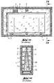
- a installation for the heat treatment of glass includes an insulated chamber 1, which can be loaded on the right side (Fig. 1a), by means of doors, in a manner not shown.
- bedroom 1 In bedroom 1 is find a moving bridge 2.
- the easel 2 has a lower frame 2a and a medial bridge wall 2b, on both sides of which is arranged a package slightly inclined by vertical ratio of glass plates 3 disposed parallel on a loading platform. Enter the different glass plates, spacers 2c vertical form interstices.
- a circulation duct 4 Under the ceiling from bedroom 1 is a circulation duct 4 with a blower 5 and a heat exchanger 6 located downstream of it, which can be adjusted in a which is not represented more precisely.
- the blower 5 sucks in the chamber 1 submitted to the atmospheric pressure from the right into the circulation duct 4.
- the airflow reaches all first heat exchanger 6 and is carried by it at the desired temperature.
- the airflow On the end wall left of the room, the airflow is firstly deflected at 90 °, then he enters Chamber 1 through a partition wall 8 provided with orifices 7, after a new deviation of 90 °, a room in which he meet the slice of the glass plates.
- the easel adjacent to the plates is essentially wrapped and swept by the airflow in the longitudinal direction.
- the temperature is transmitted from the airflow to the plates of glass and easel by convection.
- the spacers 2c prevent however the air circulation in the interstices separating the different plates 3.
- FIG. 2 represents a modified installation to create a better air flow through the plate packets of glass, which includes a room 11, the easel symmetrical 2 lying inside of it and the glass plates 3 with the spacers 2c intercalated in top view according to FIG. 1b.
- a room 11 the easel symmetrical 2 lying inside of it and the glass plates 3 with the spacers 2c intercalated in top view according to FIG. 1b.
- FIG. 2 represents the state of the symmetrical chamber during charging and unloading, while the right half illustrates its state with the blower running.
- a first step to improve the heat transfer from the blown air to the glass plates lies in a modification of the direction of circulation. It can be observed that of the two sides of the easel 2 on the longitudinal sides of the chamber 11 are installed ducts 12 equipped with integrated blowers 13 and downstream thereof, Heat exchangers 14. Blowers 13 each push back a flow of air in the vertical direction of the bottom from bedroom 11 up to its ceiling 15.
- the circulation ducts 12 are isolated from the chamber 11 by means of partition walls 16 vertical fixed, which extend over the entire length of the room between its faces of about. Under the ceiling 15, wall sections 17 bent towards the middle of the chamber are connected to the partition walls 16, which sections do not form between their edges end 18 that a discharge slot from the top 19, whose inner width is substantially less than the width of the chamber 11.
- moving walls 20 are installed in the chamber 11. These walls extend, inside the room 11, on the same length as the walls of separation 16 of the circulation ducts. They are articulated in the area of the end edges 18 of the wall sections 17 of the partition walls and can be set in different positions in a way that is not shown in more detail.
- the movable wall 20 on the left side is in a loading and unloading position, in which it applies from the outside on the wall partition 16 dividing the circulation conduit 12. In this way, there remains a relatively important between the loaded bridge 2 and the wall 20.
- the movable wall 20 on the right side is in its operating position, close as much as possible of the outer glass plate 3 of the right plate of glass, but without the to touch. On the contrary, a relatively narrow wall must remain between the wall and the glass, so that the outer face of the outer glass plate of the package is also exposed to the airflow.
- the air flows from two circulation ducts are deflected 90 ° above wall sections 17 and then are joined together and mixed in the middle of chamber 11.
- the full stream is deflected down to middle of the ceiling by means of the guiding device indicated.
- the top discharge slot 19 defines a section of relatively small total passage, so that a considerable pressure can build up on top of the pack of glass plates.
- Blowers can also be used of a type that deflects the flow of air inside their housing (cylinder or current fans transversal) and install them in the upper corners from the room.
- the type of blower and heat exchanger heat and their arrangement in the room do not clothe however not of decisive importance in the embodiment of the invention.
- the heat exchanger concept is used to indicate that the described installation allows to achieve not only a heating of the plates of glass, but also a precise course of cycles programmed temperature changes involving a successive heating and cooling.
- the installation is not therefore not limited to operation by means of air flowing.
- the installation is not no longer limited to the Heat-Soak-Test, although it is particularly adapted to its requirements.
Landscapes
- Chemical & Material Sciences (AREA)
- Engineering & Computer Science (AREA)
- Materials Engineering (AREA)
- Organic Chemistry (AREA)
- Physics & Mathematics (AREA)
- Thermal Sciences (AREA)
- Re-Forming, After-Treatment, Cutting And Transporting Of Glass Products (AREA)
- Joining Of Glass To Other Materials (AREA)
- Tables And Desks Characterized By Structural Shape (AREA)
- Processing And Handling Of Plastics And Other Materials For Molding In General (AREA)
- Furnace Details (AREA)
Description
- au moins une chambre pouvant être chauffée,
- au moins un chevalet pourvu d'entretoises pour accueillir plusieurs plaques de verre dans la chambre,
- des moyens pour produire à l'intérieur de la chambre un flux d'air réglant la température des plaques de verre par convection,
Claims (11)
- Installation pour le traitement thermique de plaques de verre (3) parallèles maintenues à distance l'une de l'autre en formant des interstices entre lesdites plaques, en particulier pour l'exécution d'un Heat- Soak-Test, qui comprend :caractérisée en ce que la section d'admission du flux d'air à l'arrivée dans les interstices est limitée aux dimensions extérieures, du côté du soufflage de l'air, de l'ensemble composé des plaques de verre (3) et du chevalet (2) situé à l'intérieur de la chambre (11) et en ce qu'une différence de pression suffisante entre le côté de soufflage de l'air dans lesdits interstices et le côté d'écoulement de l'air hors desdits interstices est créée.au moins une chambre (11) pouvant être chauffée,au moins un chevalet (2) pourvu d'entretoises (2c) pour accueillir plusieurs plaques de verre (3) dans la chambre,des moyens (13) pour produire à l'intérieur de la chambre un flux d'air réglant la température des plaques de verre par convection,
- Installation selon la revendication précédente, caractérisée en ce que l'air circulant passe par une fente de décharge par le haut (19) correspondant à la section d'admission du flux d'air et ayant pour effet que l'air circulant, après avoir traversé ladite fente, rencontre les bords supérieurs des plaques de verre et est amené de haut en bas le long des plaques de verre et à travers les interstices libres formés au moyen des entretoises (2c).
- Installation suivant l'une des revendications précédentes, caractérisée en ce que la direction principale de circulation de l'air entre les plaques de verre (3) est agencée parallèlement au sens longitudinal des entretoises (2c).
- Installation suivant la revendication précédente, caractérisée en ce que les entretoises (2c) sont agencées aussi près que possible des bords de tranche des plaques de verre.
- Installation suivant l'une quelconque des revendications précédentes, caractérisée en ce que, dans la chambre (11), est agencée au moins une paroi mobile (20) destinée à régler la section du flux d'air dans la zone du chevalet (2) se trouvant à l'intérieur de la chambre.
- Installation suivant la revendication précédente, caractérisé en ce que, en cas de réalisation symétrique, pouvant être chargée des deux côtés, du chevalet (2) utilisé à l'intérieur de la chambre (11), des parois de chambre mobiles (20) sont prévues sur les deux côtés du chevalet et s'étendent parallèlement aux plaques de verre (3).
- Installation suivant la revendication 5 ou 6, caractérisée en ce que l'air circulant passe par une fente de décharge par le haut (19) correspondant à la section d'admission du flux d'air, ladite fente étant limitée par des parois mobiles permettant de modifier sa largeur.
- Installation selon l'une des revendications 5 à 7, caractérisée en ce que des entretoises sont intercalées entre la ou les parois mobiles et la ou les plaques de verre située(s) à l'extérieur.
- Installation suivant l'une des revendications précédentes, caractérisée en ce que les moyens pour produire le flux d'air à l'intérieur de la chambre comprennent au moins un conduit de circulation (12) muni d'une soufflante (13).
- Installation suivant la revendication précédente, caractérisée en ce que, en cas d'utilisation d'un chevalet (2) symétrique dans la chambre, un conduit de circulation (12) muni de soufflantes (13) est prévu au niveau des deux côtés longitudinaux de la chambre, les flux d'air des deux conduits pouvant être réunis dans ou avant la fente de décharge par le haut (19).
- Installation suivant l'une quelconque des revendications précédentes, caractérisée en ce qu'il est prévu au moins un échangeur de chaleur (14) convenant aussi bien pour le chauffage que pour le refroidissement de l'air circulant.
Priority Applications (1)
| Application Number | Priority Date | Filing Date | Title |
|---|---|---|---|
| DK99400387T DK0940372T3 (da) | 1998-03-06 | 1999-02-18 | Anlæg til varmebehandling af glasplader |
Applications Claiming Priority (2)
| Application Number | Priority Date | Filing Date | Title |
|---|---|---|---|
| DE19809582A DE19809582C1 (de) | 1998-03-06 | 1998-03-06 | Vorrichtung zur Wärmebehandlung von Glasplatten |
| DE19809582 | 1998-03-06 |
Publications (3)
| Publication Number | Publication Date |
|---|---|
| EP0940372A2 EP0940372A2 (fr) | 1999-09-08 |
| EP0940372A3 EP0940372A3 (fr) | 2000-03-15 |
| EP0940372B1 true EP0940372B1 (fr) | 2005-06-15 |
Family
ID=7859908
Family Applications (1)
| Application Number | Title | Priority Date | Filing Date |
|---|---|---|---|
| EP99400387A Expired - Lifetime EP0940372B1 (fr) | 1998-03-06 | 1999-02-18 | Installation pour le traitement thermique de plaques de verre |
Country Status (7)
| Country | Link |
|---|---|
| EP (1) | EP0940372B1 (fr) |
| AT (1) | ATE297879T1 (fr) |
| DE (2) | DE19809582C1 (fr) |
| DK (1) | DK0940372T3 (fr) |
| ES (1) | ES2244154T3 (fr) |
| PL (1) | PL188837B1 (fr) |
| PT (1) | PT940372E (fr) |
Families Citing this family (2)
| Publication number | Priority date | Publication date | Assignee | Title |
|---|---|---|---|---|
| FI119421B (fi) * | 2004-02-20 | 2008-11-14 | Tamglass Ltd Oy | Laminoitujen lasilevyjen ilmanpoistouuni |
| FR3022904B1 (fr) * | 2014-06-27 | 2016-07-01 | Saint Gobain | Procede d'activation de couche sur substrat verrier |
Family Cites Families (6)
| Publication number | Priority date | Publication date | Assignee | Title |
|---|---|---|---|---|
| US1689048A (en) * | 1927-05-05 | 1928-10-23 | Frank W Preston | Method of and apparatus for annealing glass |
| DE685563C (de) * | 1936-01-03 | 1939-12-20 | Ludwig Kirchhoff | Waermofen mit Luftumwaelzheizung |
| US2262545A (en) * | 1936-08-31 | 1941-11-11 | Manufactures De Glaces Et Prod | Method and means for controlling heat treatments |
| US2515731A (en) * | 1947-08-19 | 1950-07-18 | Walter R Page | Heating oven for laminated glass |
| FR1407725A (fr) * | 1964-06-09 | 1965-08-06 | Four de trempe pour le verre | |
| DD159769A1 (de) * | 1981-06-22 | 1983-04-06 | Kurt Kessler | Elektrisch beheizter kammerofen zur waermebehandlung von glaserzeugnissen |
-
1998
- 1998-03-06 DE DE19809582A patent/DE19809582C1/de not_active Expired - Fee Related
-
1999
- 1999-02-18 DK DK99400387T patent/DK0940372T3/da active
- 1999-02-18 EP EP99400387A patent/EP0940372B1/fr not_active Expired - Lifetime
- 1999-02-18 AT AT99400387T patent/ATE297879T1/de active
- 1999-02-18 PT PT99400387T patent/PT940372E/pt unknown
- 1999-02-18 ES ES99400387T patent/ES2244154T3/es not_active Expired - Lifetime
- 1999-02-18 DE DE69925772T patent/DE69925772T2/de not_active Expired - Lifetime
- 1999-03-04 PL PL99331756A patent/PL188837B1/pl not_active IP Right Cessation
Also Published As
| Publication number | Publication date |
|---|---|
| DE69925772D1 (de) | 2005-07-21 |
| DK0940372T3 (da) | 2005-10-17 |
| PL188837B1 (pl) | 2005-04-29 |
| PL331756A1 (en) | 1999-09-13 |
| DE19809582C1 (de) | 1999-08-12 |
| ATE297879T1 (de) | 2005-07-15 |
| PT940372E (pt) | 2005-11-30 |
| DE69925772T2 (de) | 2006-05-18 |
| ES2244154T3 (es) | 2005-12-01 |
| EP0940372A3 (fr) | 2000-03-15 |
| EP0940372A2 (fr) | 1999-09-08 |
Similar Documents
| Publication | Publication Date | Title |
|---|---|---|
| EP0090790B1 (fr) | Appareil pour le traitement thermique d'objets par convection | |
| FR2526920A1 (fr) | Bloc de grille d'un caillebotis pour une grille d'incineration d'ordures | |
| EP0940372B1 (fr) | Installation pour le traitement thermique de plaques de verre | |
| EP0044788B1 (fr) | Four pour le chauffage de feuilles de verre suspendues en position verticale | |
| FR2869400A1 (fr) | Dispositif terminal de production d'air de d'alimentation | |
| EP3518679B1 (fr) | Module de cuisson de four pour produits de boulangerie, de viennoiserie et similaires et four tunnel lineaire comportant au moins un tel module | |
| EP1362012B1 (fr) | Dispositif de soufflage d'un fluide sur au moins une face d'un element mince, et unite de soufflage associee | |
| WO2015044587A1 (fr) | Procédé de cuisson de produits de boulangerie, viennoiserie et pâtisserie avec préchauffage direct, et ses dispositifs de mise en oeuvre | |
| FR2785901A1 (fr) | Etuve pour detecter des inclusions de sulfures de nickel dans les vitrages | |
| EP2200946B1 (fr) | Four et procédé de trempe comportant plusieurs dispositifs de soufflage d'un fluide sur une face d'un element mince de type vitrage | |
| FR2790698A1 (fr) | Dispositif pour le traitement thermique a haute temperature d'une matiere ligneuse | |
| FR2536835A1 (fr) | Perfectionnement aux foyers fermes en particulier pour cheminees | |
| EP0512900B1 (fr) | Procédé et dispositif pour obtenir les températures désirées pour un courant de verre dans un feeder | |
| EP1906125B1 (fr) | Four portique | |
| BE1005166A5 (fr) | Arche de recuisson. | |
| BE538159A (fr) | ||
| FR2770625A1 (fr) | Element echangeur de chaleur a haut rendement destine a constituer le corps de chauffe d'une chaudiere sectionnable | |
| BE705875A (fr) | ||
| CH354047A (fr) | Four à cuisson | |
| CH437656A (fr) | Four pour produits céramiques | |
| BE479513A (fr) | ||
| BE550153A (fr) | ||
| BE697634A (fr) | ||
| BE474816A (fr) | ||
| FR2991434A1 (fr) | Systeme de guidage de fumees d'une cheminee |
Legal Events
| Date | Code | Title | Description |
|---|---|---|---|
| PUAI | Public reference made under article 153(3) epc to a published international application that has entered the european phase |
Free format text: ORIGINAL CODE: 0009012 |
|
| AK | Designated contracting states |
Kind code of ref document: A2 Designated state(s): AT BE CH DE DK ES FI FR GB IE IT LI LU NL PT SE |
|
| AX | Request for extension of the european patent |
Free format text: AL;LT;LV;MK;RO;SI |
|
| PUAL | Search report despatched |
Free format text: ORIGINAL CODE: 0009013 |
|
| AK | Designated contracting states |
Kind code of ref document: A3 Designated state(s): AT BE CH CY DE DK ES FI FR GB GR IE IT LI LU MC NL PT SE |
|
| AX | Request for extension of the european patent |
Free format text: AL;LT;LV;MK;RO;SI |
|
| 17P | Request for examination filed |
Effective date: 20000705 |
|
| AKX | Designation fees paid |
Free format text: AT BE CH DE DK ES FI FR GB IE IT LI LU NL PT SE |
|
| 17Q | First examination report despatched |
Effective date: 20030207 |
|
| GRAP | Despatch of communication of intention to grant a patent |
Free format text: ORIGINAL CODE: EPIDOSNIGR1 |
|
| GRAS | Grant fee paid |
Free format text: ORIGINAL CODE: EPIDOSNIGR3 |
|
| RAP1 | Party data changed (applicant data changed or rights of an application transferred) |
Owner name: SAINT-GOBAIN GLASS FRANCE |
|
| GRAA | (expected) grant |
Free format text: ORIGINAL CODE: 0009210 |
|
| AK | Designated contracting states |
Kind code of ref document: B1 Designated state(s): AT BE CH DE DK ES FI FR GB IE IT LI LU NL PT SE |
|
| REG | Reference to a national code |
Ref country code: GB Ref legal event code: FG4D Free format text: NOT ENGLISH Ref country code: CH Ref legal event code: EP |
|
| REF | Corresponds to: |
Ref document number: 69925772 Country of ref document: DE Date of ref document: 20050721 Kind code of ref document: P |
|
| REG | Reference to a national code |
Ref country code: IE Ref legal event code: FG4D Free format text: LANGUAGE OF EP DOCUMENT: FRENCH |
|
| REG | Reference to a national code |
Ref country code: CH Ref legal event code: NV Representative=s name: KIRKER & CIE SA |
|
| REG | Reference to a national code |
Ref country code: SE Ref legal event code: TRGR |
|
| GBT | Gb: translation of ep patent filed (gb section 77(6)(a)/1977) |
Effective date: 20050921 |
|
| REG | Reference to a national code |
Ref country code: DK Ref legal event code: T3 |
|
| REG | Reference to a national code |
Ref country code: ES Ref legal event code: FG2A Ref document number: 2244154 Country of ref document: ES Kind code of ref document: T3 |
|
| PLBE | No opposition filed within time limit |
Free format text: ORIGINAL CODE: 0009261 |
|
| STAA | Information on the status of an ep patent application or granted ep patent |
Free format text: STATUS: NO OPPOSITION FILED WITHIN TIME LIMIT |
|
| 26N | No opposition filed |
Effective date: 20060316 |
|
| PGFP | Annual fee paid to national office [announced via postgrant information from national office to epo] |
Ref country code: IT Payment date: 20120222 Year of fee payment: 14 |
|
| PGFP | Annual fee paid to national office [announced via postgrant information from national office to epo] |
Ref country code: LU Payment date: 20130219 Year of fee payment: 15 |
|
| PGFP | Annual fee paid to national office [announced via postgrant information from national office to epo] |
Ref country code: SE Payment date: 20130212 Year of fee payment: 15 Ref country code: DE Payment date: 20130213 Year of fee payment: 15 Ref country code: IE Payment date: 20130212 Year of fee payment: 15 Ref country code: GB Payment date: 20130213 Year of fee payment: 15 Ref country code: CH Payment date: 20130212 Year of fee payment: 15 Ref country code: FI Payment date: 20130212 Year of fee payment: 15 Ref country code: DK Payment date: 20130212 Year of fee payment: 15 Ref country code: ES Payment date: 20130215 Year of fee payment: 15 |
|
| PGFP | Annual fee paid to national office [announced via postgrant information from national office to epo] |
Ref country code: NL Payment date: 20130209 Year of fee payment: 15 |
|
| PGFP | Annual fee paid to national office [announced via postgrant information from national office to epo] |
Ref country code: PT Payment date: 20130206 Year of fee payment: 15 Ref country code: AT Payment date: 20130110 Year of fee payment: 15 |
|
| PGFP | Annual fee paid to national office [announced via postgrant information from national office to epo] |
Ref country code: BE Payment date: 20130312 Year of fee payment: 15 |
|
| PGFP | Annual fee paid to national office [announced via postgrant information from national office to epo] |
Ref country code: FR Payment date: 20130604 Year of fee payment: 15 |
|
| REG | Reference to a national code |
Ref country code: PT Ref legal event code: MM4A Free format text: LAPSE DUE TO NON-PAYMENT OF FEES Effective date: 20140818 |
|
| BERE | Be: lapsed |
Owner name: *SAINT-GOBAIN GLASS FRANCE Effective date: 20140228 |
|
| REG | Reference to a national code |
Ref country code: DE Ref legal event code: R119 Ref document number: 69925772 Country of ref document: DE |
|
| REG | Reference to a national code |
Ref country code: NL Ref legal event code: V1 Effective date: 20140901 |
|
| REG | Reference to a national code |
Ref country code: DK Ref legal event code: EBP Effective date: 20140228 |
|
| PG25 | Lapsed in a contracting state [announced via postgrant information from national office to epo] |
Ref country code: LU Free format text: LAPSE BECAUSE OF NON-PAYMENT OF DUE FEES Effective date: 20140218 |
|
| REG | Reference to a national code |
Ref country code: CH Ref legal event code: PL Ref country code: SE Ref legal event code: EUG |
|
| REG | Reference to a national code |
Ref country code: AT Ref legal event code: MM01 Ref document number: 297879 Country of ref document: AT Kind code of ref document: T Effective date: 20140218 |
|
| GBPC | Gb: european patent ceased through non-payment of renewal fee |
Effective date: 20140218 |
|
| PG25 | Lapsed in a contracting state [announced via postgrant information from national office to epo] |
Ref country code: NL Free format text: LAPSE BECAUSE OF NON-PAYMENT OF DUE FEES Effective date: 20140901 Ref country code: LI Free format text: LAPSE BECAUSE OF NON-PAYMENT OF DUE FEES Effective date: 20140228 Ref country code: FI Free format text: LAPSE BECAUSE OF NON-PAYMENT OF DUE FEES Effective date: 20140218 Ref country code: CH Free format text: LAPSE BECAUSE OF NON-PAYMENT OF DUE FEES Effective date: 20140228 |
|
| REG | Reference to a national code |
Ref country code: FR Ref legal event code: ST Effective date: 20141031 |
|
| REG | Reference to a national code |
Ref country code: DE Ref legal event code: R119 Ref document number: 69925772 Country of ref document: DE Effective date: 20140902 |
|
| PG25 | Lapsed in a contracting state [announced via postgrant information from national office to epo] |
Ref country code: AT Free format text: LAPSE BECAUSE OF NON-PAYMENT OF DUE FEES Effective date: 20140218 Ref country code: SE Free format text: LAPSE BECAUSE OF NON-PAYMENT OF DUE FEES Effective date: 20140219 |
|
| REG | Reference to a national code |
Ref country code: IE Ref legal event code: MM4A |
|
| PG25 | Lapsed in a contracting state [announced via postgrant information from national office to epo] |
Ref country code: PT Free format text: LAPSE BECAUSE OF NON-PAYMENT OF DUE FEES Effective date: 20140818 |
|
| PG25 | Lapsed in a contracting state [announced via postgrant information from national office to epo] |
Ref country code: IE Free format text: LAPSE BECAUSE OF NON-PAYMENT OF DUE FEES Effective date: 20140218 Ref country code: DE Free format text: LAPSE BECAUSE OF NON-PAYMENT OF DUE FEES Effective date: 20140902 Ref country code: BE Free format text: LAPSE BECAUSE OF NON-PAYMENT OF DUE FEES Effective date: 20140228 Ref country code: DK Free format text: LAPSE BECAUSE OF NON-PAYMENT OF DUE FEES Effective date: 20140228 Ref country code: FR Free format text: LAPSE BECAUSE OF NON-PAYMENT OF DUE FEES Effective date: 20140228 Ref country code: GB Free format text: LAPSE BECAUSE OF NON-PAYMENT OF DUE FEES Effective date: 20140218 |
|
| REG | Reference to a national code |
Ref country code: ES Ref legal event code: FD2A Effective date: 20150327 |
|
| PG25 | Lapsed in a contracting state [announced via postgrant information from national office to epo] |
Ref country code: ES Free format text: LAPSE BECAUSE OF NON-PAYMENT OF DUE FEES Effective date: 20140219 |
|
| PG25 | Lapsed in a contracting state [announced via postgrant information from national office to epo] |
Ref country code: IT Free format text: LAPSE BECAUSE OF NON-PAYMENT OF DUE FEES Effective date: 20140218 |