EP0940339A1 - Kontinuierliches Verfahren und Maschine zum Umhüllen von Gegenständen - Google Patents
Kontinuierliches Verfahren und Maschine zum Umhüllen von Gegenständen Download PDFInfo
- Publication number
- EP0940339A1 EP0940339A1 EP99104385A EP99104385A EP0940339A1 EP 0940339 A1 EP0940339 A1 EP 0940339A1 EP 99104385 A EP99104385 A EP 99104385A EP 99104385 A EP99104385 A EP 99104385A EP 0940339 A1 EP0940339 A1 EP 0940339A1
- Authority
- EP
- European Patent Office
- Prior art keywords
- sheet
- seat
- spindle
- wrapping
- machine
- Prior art date
- Legal status (The legal status is an assumption and is not a legal conclusion. Google has not performed a legal analysis and makes no representation as to the accuracy of the status listed.)
- Granted
Links
Images
Classifications
-
- B—PERFORMING OPERATIONS; TRANSPORTING
- B65—CONVEYING; PACKING; STORING; HANDLING THIN OR FILAMENTARY MATERIAL
- B65B—MACHINES, APPARATUS OR DEVICES FOR, OR METHODS OF, PACKAGING ARTICLES OR MATERIALS; UNPACKING
- B65B19/00—Packaging rod-shaped or tubular articles susceptible to damage by abrasion or pressure, e.g. cigarettes, cigars, macaroni, spaghetti, drinking straws or welding electrodes
- B65B19/02—Packaging cigarettes
- B65B19/22—Wrapping the cigarettes; Packaging the cigarettes in containers formed by folding wrapping material around formers
- B65B19/223—Wrapping the cigarettes; Packaging the cigarettes in containers formed by folding wrapping material around formers in a curved path; in a combination of straight and curved paths, e.g. on rotary tables or other endless conveyors
- B65B19/225—Wrapping the cigarettes; Packaging the cigarettes in containers formed by folding wrapping material around formers in a curved path; in a combination of straight and curved paths, e.g. on rotary tables or other endless conveyors the conveyors having continuous movement
-
- B—PERFORMING OPERATIONS; TRANSPORTING
- B65—CONVEYING; PACKING; STORING; HANDLING THIN OR FILAMENTARY MATERIAL
- B65B—MACHINES, APPARATUS OR DEVICES FOR, OR METHODS OF, PACKAGING ARTICLES OR MATERIALS; UNPACKING
- B65B11/00—Wrapping, e.g. partially or wholly enclosing, articles or quantities of material, in strips, sheets or blanks, of flexible material
- B65B11/06—Wrapping articles, or quantities of material, by conveying wrapper and contents in common defined paths
- B65B11/28—Wrapping articles, or quantities of material, by conveying wrapper and contents in common defined paths in a curved path, e.g. on rotary tables or turrets
- B65B11/30—Wrapping articles, or quantities of material, by conveying wrapper and contents in common defined paths in a curved path, e.g. on rotary tables or turrets to fold the wrappers in tubular form about contents
Definitions
- the present invention relates to a continuous product wrapping method.
- Cigarette packing machines are known to feature a step-operated or continuous wrapping wheel having a number of peripheral seats, each for receiving a respective group of cigarettes - normally comprising twenty cigarettes arranged in three layers - which is fed to a respective seat on the wrapping wheel from a respective seat on a transfer wheel.
- a sheet of foil is fed between the wheels along the transfer path of the group from one wheel to the other, so that, when transferring the group, the sheet is inserted inside the respective seat on the wrapping wheel and simultaneously folded into a U about the group.
- US Patent No. 5,392,586 describes a continuous wrapping unit operating according to the above known method, but which is complex in design and therefore expensive to produce. That is, the continuous movement of the wheels and the continually-changing positions of the seats with respect to each other and to the sheet of wrapping material call for complex mechanical solutions to keep the seats facing each other, and for synchronously inserting the sheet of wrapping material between the seats.
- the above method fails to provide for effectively folding the sheet of foil, on account of the increasingly fast operating speeds of modern packing machines - by now capable of producing over ten packets a second - reducing the folding time per sheet to a few hundredths of a second, and so stressing the sheet as to result in premature partial to total tearing of the tear-off portion.
- GB patent application No. 2138382 discloses a continuos cigarette packing machine having a conveyor supporting a plurality of seats, each of which is capable of receiving and conveying a relevant sheet of wrapping material and a respective group of cigarettes.
- the conveyor feeds each seat through a first loading station, in which the seat receives the relevant sheet of wrapping material, and a successive second loading station, in which the seat receives the relevant product.
- Each sheet of wrapping material is fed to the relevant seat by a respective folding spindle, which is fed through an output of a line for supplying wrapping material to pick up and fold the sheet of wrapping material at least partly into a U.
- the folding spindle is then fed through the first loading station to be inserted into the relevant seat for feeding the sheet arranged in a substantially U-folded configuration inside the relevant seat.
- a method of continuously wrapping a product comprising the steps of feeding a sheet of wrapping material to an output of a line for supplying wrapping material; coupling said sheet with a folding spindle, about which said sheet is folded at least partly into a U; feeding said folding spindle together with said sheet to a first loading station; inserting, at said first loading station said folding spindle into a seat on a wrapping conveyor for feeding the sheet arranged in a substantially U-folded configuration inside said seat; feeding the seat and the sheet through a second loading station to receive said product; and feeding the seat together with the sheet and the product through at least one folding station to fold said sheet about said product; the method being characterized in that said seat is set in a first open position, in which each of the said lateral walls forms with said bottom wall an obtuse angle, to receive said sheet and said product and in a second closed position, in which each of the said lateral walls forms with said bottom wall a substantially right angle, to hold together said sheet and said
- the present invention also relates to a machine for continuously wrapping a product.
- a machine for continuously wrapping a product comprising a line for supplying wrapping material and having an output; at least one seat for receiving and conveying said sheet of wrapping material and a respective product; a wrapping conveyor carrying said seat and having a first loading station for a sheet of wrapping material, a second loading station for said product, located downstream from said first loading station in a traveling direction of said seat, and at least one folding station to fold said sheet about said product; at least one folding spindle; and first actuating means for feeding the folding spindle through said output to pick up and fold said sheet of wrapping material at least partly into a U about the folding spindle, and then through said first loading station to insert said folding spindle into said seat for feeding the sheet arranged in a substantially U-folded configuration inside said seat; the machine being characterized in that said two lateral walls are rotary connected to said bottom wall; the machine further comprising second actuating means for setting said seat in a first open position, in which each of the said lateral walls forms with
- the additional features set out in Claims 3 and 12 allow a very good "U" folding of each sheet in the relevant seat. Furthermore, the additional feature set out in Claim 6 substantially allows canceling residual creeping of the external surfaces of the spindle with the internal surfaces of the seat.
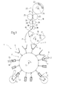
- Number 1 in Figure 1 indicates as a whole an automatic packing machine for producing packets of cigarettes (not shown), wherein a group 2 of cigarettes is first wrapped in a sheet 3 of foil wrapping material, and is then inserted inside a blank (not shown) which is folded about group 2 to form a packet of cigarettes (not shown).
- Packing machine 1 comprises a wrapping wheel 4 powered to rotate continuously (clockwise in Figure 1) about a central axis 5 perpendicular to the Figure 1 plane, and having a number of peripheral seats 6 equally spaced about axis 5.
- Each seat 6 provides for receiving and conveying first a respective sheet 3 of wrapping material folded substantially into a U, and then also a respective group 2 of cigarettes, which is wrapped in sheet 3 of wrapping material.
- Packing machine 1 also comprises a supply device 7 for successively feeding sheets 3 of wrapping material to respective seats 6 on wrapping wheel 4 at a loading station 8; a known loading station 9 where groups 2 of cigarettes are fed successively to respective seats 6 on wrapping wheel 4; two known folding devices 10 and 11 for folding a sheet 3 of wrapping material about a respective group 2 of cigarettes at respective folding stations 12 and 13; and an unloading station 14 where groups 2 wrapped in respective sheets 3 of wrapping material are extracted successively from respective seats 6 on wrapping wheel 4 and fed to successive known wrapping units (not shown).
- a supply device 7 for successively feeding sheets 3 of wrapping material to respective seats 6 on wrapping wheel 4 at a loading station 8
- a known loading station 9 where groups 2 of cigarettes are fed successively to respective seats 6 on wrapping wheel 4
- two known folding devices 10 and 11 for folding a sheet 3 of wrapping material about a respective group 2 of cigarettes at respective folding stations 12 and 13
- an unloading station 14 where groups 2 wrapped in respective sheets 3 of wrapping material are extracted successively from respective seats 6 on wrapping wheel 4 and fed to
- Supply device 7 comprises a transfer wheel 15 powered to rotate continuously (anticlockwise in Figure 1) about a central axis 16 parallel to axis 5, and having a number of peripheral folding spindles 17 equally spaced about axis 16.
- Each folding spindle 17 provides for picking up a respective sheet 3 of wrapping material from a known supply unit 18, at an output of unit 18 defined by a supply station 19, and for feeding sheet 3 of wrapping material to a respective seat 6 at loading station 8.
- Supply device 7 also comprises a folding element P located along the path of folding spindles 17 between supply station 19 and loading station 8.
- Supply unit 18 comprises a known unwinding station 20 where a strip 21 of foil is unwound off a reel 22 supported on a pin 23; a known embossing station 24 having two embossing rollers 25; two feed rollers 26 for feeding strip 21 along supply unit 18; and a known cutting station 27 having two cutting rollers 28.
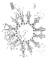
- folding spindles 17 are connected to transfer wheel 15 via the interposition of respective rocker arms 29, each of which is hinged to transfer wheel 15 to swing, with respect to transfer wheel 15, about an axis 30 parallel to axis 16.
- Each rocker arm 29 comprises a first arm 31 extending towards axis 16 and fitted on the free end with a tappet roller 32 connected to a fixed cam 33 defining, with roller 32, a control device 34 for controlling the angular position of rocker arm 29 about respective axis 30; and a second arm 35 extending outwards of transfer wheel 15 and fitted on the free end with a respective folding spindle 17.
- Each folding spindle 17 is substantially trapezoidal and is defined by a large bottom surface 36 parallel to axis 16, by a small top surface 37 parallel to surface 36 and outwards of surface 36 with respect to axis 16, and by two inclined lateral surfaces 38 and 39 located respectively at the front and rear with reference to the traveling direction of folding spindle 17, and which form, with top surface 37, two edges 40 parallel to axis 16.
- Each folding spindle 17 is fixed to respective arm 35 at bottom surface 36, and comprises a known pneumatic suction device 41, which comes out through a number of suction holes 42 formed in surfaces 37 and 38 to retain a respective sheet 3 of wrapping material.
- Each folding spindle 17 comprises an inner body 43 of nondeformable material, typically metal, covered at surfaces 37, 38 and 39 by a thin outer layer 44 of deformable material, typically rubber or sponge. In an alternative embodiment not shown, folding spindles 17 have no outer layers 44 of deformable material.
- Each folding spindle 17 also comprises a gripper 45 hinged to bottom surface 36 to retain a respective sheet 3 of wrapping material on lateral surface 38.
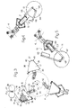
- each seat 6 is defined on a respective support 46 connected to wrapping wheel 4 via the interposition of a respective rocker arm 47 hinged to wrapping wheel 4 to swing, with respect to wrapping wheel 4, about an axis 48 parallel to axis 5.
- Each rocker arm 47 comprises a first arm 49 extending towards axis 5 and fitted on the free end with a tappet roller 50 connected to a fixed cam 51 defining, with roller 50, a control device 52 for controlling the angular position of rocker arm 47 about respective axis 48; and a second arm 53 extending outwards of wrapping wheel 4 and fitted on the free end with a respective support 46.
- Each seat 6 in respective support 46 is defined by a bottom wall 54 fitted to respective arm 53, and by two lateral walls 55 hinged on opposite sides of wall 54 to swing, about respective axes 56 parallel to axis 5, between an open position and a closed position.
- the two lateral walls 55 of each seat 6 In the open position, the two lateral walls 55 of each seat 6 form an obtuse angle with bottom wall 54, and the section of seat 6 is in the form of an isosceles trapezium negatively reproducing the shape of folding spindle 17.
- the two lateral walls 55 of each seat 6 form a substantially right angle with bottom wall 54, and seat 6 has a substantially rectangular section of substantially the same dimensions as a group 2 of cigarettes.
- a control device 57 comprising two first arms 58, each of which has one end fitted to a respective lateral wall 55, and the other end hinged to one end of a second arm 59.
- the other end of each arm 59 is hinged to a tubular body 60, which slides along respective arm 53 and comprises an appendix 61, to the free end of which is hinged a tappet roller 62 connected to a fixed cam 63 to control the sliding movement of body 60 along respective arm 53.
- the inner surfaces of walls 54 and 55 comprise a number of holes (not shown) connected to a known suction device (not shown) carried by wrapping wheel 4.
- folding device 10 comprises a cylinder 64 rotating about a fixed axis 65 parallel to axis 5; and a pair of folding elements 66 hinged to cylinder 64, and which are swung by a known cam control device (not shown) to fold a sheet 3 of wrapping material longitudinally about a respective group 2 of cigarettes.
- folding device 11 comprises a cylinder 67 rotating about a fixed axis 68 parallel to axis 5; and two pairs of folding elements 69 (only one shown in Figure 5) hinged to cylinder 67, and which are swung by a known cam control device (not shown) to fold both ends (only one shown in Figure 5) of a sheet 3 of wrapping material about a respective group 2 of cigarettes.
- packing machine 1 Operation of packing machine 1 will now be described with reference to one folding spindle 17 and one corresponding seat 6, and as of the instant in which folding spindle 17 is brought into supply station 19 by transfer wheel 15 rotating about axis 16.
- sheet 3 of wrapping material is embossed in known manner by embossing rollers 25, and is worked by a first pair of blades (not shown) on cutting rollers 28, which form on sheet 3 said preformed tear line (not shown).
- Sheet 3 of wrapping material is drawn out of supply unit 18 by folding spindle 17 rotating continuously about axis 16, is wound about folding spindle 17, and is folded substantially into an L about the edge 40 defined between surfaces 37 and 38, and therefore also onto surface 37, from which a rear portion of sheet 3 of wrapping material projects rearwards and is substantially coplanar with the intermediate portion of sheet 3 contacting surface 37.
- sheet 3 of wrapping material is detached in known manner from the rest of foil strip 21 by a second pair of blades (not shown) on cutting rollers 28, and is transferred by folding spindle 17 to loading station 8. Between supply station 19 and loading station 8, sheet 3 of wrapping material is engaged by folding element P, which assists in retaining sheet 3 of wrapping material on front edge 40 and top surface 37.
- control device 57 keeps seat 6 in said open position.
- folding spindle 17 and corresponding seat 6 are swung by respective control devices 34 and 52 about respective axes 30 and 48 in advance with respect to transfer wheel 15 and wrapping wheel 4 respectively; which advanced swings are continued until folding spindle 17 is positioned substantially facing seat 6 and begins penetrating and gradually meshing with seat 6 in substantially the same way as a gear tooth.
- control devices 34 and 52 begin delaying folding spindle 17 with respect to transfer wheel 15 and seat 6 with respect to wrapping wheel 4.
- folding spindle 17 folds the rear portion of sheet 3 about the rear edge 40 and so folds sheet 3 into a U onto lateral walls 55 of seat 6.
- folding spindle 17 and seat 6 act as a punch and die respectively to effectively fold sheet 3 of wrapping material without subjecting sheet 3 to excessive mechanical stress possibly resulting in partial or total tearing of said tear-off portion (not shown) of sheet 3.
- An important, though not essential, role in reducing mechanical stress on sheet 3 is played by the outer layer 44 of deformable material of folding spindle 17.
- folding spindle 17 disengages seat 6, which is fed, by wrapping wheel 4 rotating continuously, from loading station 8 to loading station 9, where seat 6 receives a respective group 2 of cigarettes from a known supply conveyor (not shown).
- control device 57 sets seat 6 to said closed position to retain the whole formed by group 2 and by sheet 3 folded into a U about group 2.
- Seat 6 is then fed through folding stations 12 and 13 where, in known manner, folding devices 10 and 11 provide respectively for longitudinally folding and folding the ends of sheet 3 about group 2 to form about group 2 a wrapping 70.
- seat 6 is fed through unloading station 14 where the whole defined by group 2 and by wrapping 70 is fed in known manner to a known follow-up wrapping unit (not shown).
- sheet 3 of wrapping material once extracted from supply unit 18, is wound about folding spindle 17 and folded substantially into a U onto lateral surfaces 38, 39 and top surface 37 of folding spindle 17.
Applications Claiming Priority (2)
| Application Number | Priority Date | Filing Date | Title |
|---|---|---|---|
| ITBO980129 | 1998-03-05 | ||
| IT98BO000129A IT1299880B1 (it) | 1998-03-05 | 1998-03-05 | Metodo e macchina per l'incarto in continuo di un prodotto. |
Publications (2)
| Publication Number | Publication Date |
|---|---|
| EP0940339A1 true EP0940339A1 (de) | 1999-09-08 |
| EP0940339B1 EP0940339B1 (de) | 2004-03-03 |
Family
ID=11342979
Family Applications (1)
| Application Number | Title | Priority Date | Filing Date |
|---|---|---|---|
| EP99104385A Expired - Lifetime EP0940339B1 (de) | 1998-03-05 | 1999-03-04 | Kontinuierliches Verfahren und Maschine zum Umhüllen von Gegenständen |
Country Status (7)
| Country | Link |
|---|---|
| US (1) | US6141944A (de) |
| EP (1) | EP0940339B1 (de) |
| CN (2) | CN1121967C (de) |
| DE (1) | DE69915145T2 (de) |
| ES (1) | ES2214762T3 (de) |
| IT (1) | IT1299880B1 (de) |
| RU (1) | RU2223898C2 (de) |
Cited By (8)
| Publication number | Priority date | Publication date | Assignee | Title |
|---|---|---|---|---|
| EP1145957A1 (de) * | 2000-04-12 | 2001-10-17 | G.D Societa' Per Azioni | Verfahren und Gerät zum formen von schlauchförmigen Verpackungshüllen in einer Zigarettenverpackungsmaschine |
| EP1176657A1 (de) | 2000-07-25 | 2002-01-30 | BM-Battery Machines GmbH | Vorrichtung zum Einführen von Batterieoder Akkumulatorplatten in Hüllen aus Separatormaterial |
| WO2003057567A1 (de) * | 2002-01-11 | 2003-07-17 | Focke & Co. (Gmbh & Co.) | Vorrichtung zum herstellen von zigaretten-packungen |
| EP1533232A1 (de) * | 2003-11-21 | 2005-05-25 | G.D Societ Per Azioni | Verpackungsvorrichtung |
| EP1842774A1 (de) * | 2006-04-04 | 2007-10-10 | G.D Societ Per Azioni | Verfahren und Maschine zum Verpacken von Artikeln |
| WO2016008559A1 (de) * | 2014-07-16 | 2016-01-21 | Focke & Co. (Gmbh & Co. Kg) | Verfahren und vorrichtung zum herstellen von packungen, insbesondere zigarettenpackungen |
| WO2016066989A1 (en) * | 2014-10-31 | 2016-05-06 | British American Tobacco (Investments) Limited | Apparatus and method for manufacturing a smoking article pack |
| IT201600116650A1 (it) * | 2016-11-18 | 2018-05-18 | Cmfima S R L | Gruppo di incarto |
Families Citing this family (13)
| Publication number | Priority date | Publication date | Assignee | Title |
|---|---|---|---|---|
| IT1309962B1 (it) * | 1999-04-08 | 2002-02-05 | Azionaria Costruzioni Acma Spa | Metodo e dispositivo per l'incarto in continuo di prodotti |
| ITBO20070439A1 (it) * | 2007-06-26 | 2008-12-27 | Gd Spa | Metodo di piegatura di un foglio di incarto attorno ad un gruppo di sigarette e corrispondente pacchetto di sigarette |
| ITBO20070492A1 (it) * | 2007-07-18 | 2007-10-17 | Gd Spa | Metodo di piegatura di un foglio di incarto rettangolare attorno ad un articolo parallelepipedo per formare un incarto tubolare avente una estremita aperta. |
| ITBO20080092A1 (it) * | 2008-02-13 | 2009-08-14 | Gd Spa | Macchina impacchettatrice di sigarette per la realizzazione di un pacchetto rigido con coperchio incernierato. |
| CN201296392Y (zh) * | 2008-11-01 | 2009-08-26 | 魏徽 | 灌装机包装袋接收夹持装置 |
| IT1392017B1 (it) * | 2008-12-12 | 2012-02-09 | Ima Flavour S R L Ora Ima Ind S R L | Macchina per la realizzazione di sacchetti-filtro in bustine con prodotti da infusione |
| IT1401804B1 (it) * | 2010-06-30 | 2013-08-28 | Azionaria Costruzioni Acma Spa | Macchina di incarto per prodotti. |
| EP2688805B1 (de) * | 2011-03-23 | 2014-12-31 | Robert Bosch GmbH | Verfahren zum verpacken von produkten, insbesondere von schokolade oder dergleichen und anlage zur durchführung des verfahrens |
| US9003747B2 (en) * | 2012-04-23 | 2015-04-14 | Alain Cerf | Process and apparatus for increasing stacking strength of film wrapped articles |
| PT3733383T (pt) * | 2019-05-02 | 2023-03-15 | Teepack Spezialmaschinen Gmbh & Co Kg | Dispositivo e processo para a produção de uma saqueta dotada de um invólucro, contendo um material passível de infusão |
| US11414222B2 (en) * | 2019-10-23 | 2022-08-16 | Create Technologies, Inc. | Automated system for the integration of a liner and envelope |
| EP3960427A1 (de) | 2020-08-31 | 2022-03-02 | Teepack Spezialmaschinen GmbH & Co. KG | Vorrichtung zum herstellen eines in einer umhüllung aufgenommenen beutels |
| CN115973509B (zh) * | 2023-03-18 | 2023-05-16 | 河北威达蓝海环保科技股份有限公司 | 脱硝催化剂烘干前自动包装设备 |
Citations (5)
| Publication number | Priority date | Publication date | Assignee | Title |
|---|---|---|---|---|
| GB906379A (en) * | 1957-08-12 | 1962-09-19 | Novotechnics Ltd | Machine for packing and wrapping articles |
| GB1570605A (en) * | 1976-03-27 | 1980-07-02 | Molins Ltd | Wrapping groups of cigarettes |
| GB2138382A (en) | 1983-04-15 | 1984-10-24 | Molins Plc | Cigarette packing machines |
| US5392586A (en) | 1991-03-29 | 1995-02-28 | Japan Tobacco, Inc. | Article transferring/wrapping apparatus |
| DE19502562A1 (de) * | 1995-01-27 | 1996-08-01 | Pactec Verpackungsmaschinen Fa | Verfahren und Einrichtung zum Einhüllen von Gütern in plastisch verformbares, folienartiges Verpackungsmaterial |
Family Cites Families (3)
| Publication number | Priority date | Publication date | Assignee | Title |
|---|---|---|---|---|
| DE2949252A1 (de) * | 1979-12-07 | 1981-06-11 | Focke & Co, 2810 Verden | Verfahren und vorrichtung zum verpacken von zigaretten o.dgl. |
| US4607477A (en) * | 1983-04-15 | 1986-08-26 | Molins Plc | Cigarette packing machines |
| IT1285921B1 (it) * | 1996-05-06 | 1998-06-26 | Gd Spa | Metodo per la manipolazione di prodotti |
-
1998
- 1998-03-05 IT IT98BO000129A patent/IT1299880B1/it active IP Right Grant
-
1999
- 1999-03-04 ES ES99104385T patent/ES2214762T3/es not_active Expired - Lifetime
- 1999-03-04 RU RU99104399/12A patent/RU2223898C2/ru not_active IP Right Cessation
- 1999-03-04 DE DE69915145T patent/DE69915145T2/de not_active Expired - Fee Related
- 1999-03-04 EP EP99104385A patent/EP0940339B1/de not_active Expired - Lifetime
- 1999-03-05 CN CN99105979A patent/CN1121967C/zh not_active Expired - Fee Related
- 1999-03-05 US US09/263,964 patent/US6141944A/en not_active Expired - Fee Related
- 1999-03-05 CN CNB991056256A patent/CN1174840C/zh not_active Expired - Fee Related
Patent Citations (5)
| Publication number | Priority date | Publication date | Assignee | Title |
|---|---|---|---|---|
| GB906379A (en) * | 1957-08-12 | 1962-09-19 | Novotechnics Ltd | Machine for packing and wrapping articles |
| GB1570605A (en) * | 1976-03-27 | 1980-07-02 | Molins Ltd | Wrapping groups of cigarettes |
| GB2138382A (en) | 1983-04-15 | 1984-10-24 | Molins Plc | Cigarette packing machines |
| US5392586A (en) | 1991-03-29 | 1995-02-28 | Japan Tobacco, Inc. | Article transferring/wrapping apparatus |
| DE19502562A1 (de) * | 1995-01-27 | 1996-08-01 | Pactec Verpackungsmaschinen Fa | Verfahren und Einrichtung zum Einhüllen von Gütern in plastisch verformbares, folienartiges Verpackungsmaterial |
Cited By (13)
| Publication number | Priority date | Publication date | Assignee | Title |
|---|---|---|---|---|
| EP1145957A1 (de) * | 2000-04-12 | 2001-10-17 | G.D Societa' Per Azioni | Verfahren und Gerät zum formen von schlauchförmigen Verpackungshüllen in einer Zigarettenverpackungsmaschine |
| US6513533B2 (en) | 2000-04-12 | 2003-02-04 | G.D Societa' Per Azioni | Method for forming tubular wrappings on a cigarette packing machine |
| EP1176657A1 (de) | 2000-07-25 | 2002-01-30 | BM-Battery Machines GmbH | Vorrichtung zum Einführen von Batterieoder Akkumulatorplatten in Hüllen aus Separatormaterial |
| WO2003057567A1 (de) * | 2002-01-11 | 2003-07-17 | Focke & Co. (Gmbh & Co.) | Vorrichtung zum herstellen von zigaretten-packungen |
| EP1533232A1 (de) * | 2003-11-21 | 2005-05-25 | G.D Societ Per Azioni | Verpackungsvorrichtung |
| US7127873B2 (en) | 2003-11-21 | 2006-10-31 | G.D. Societa' Per Azioni | Product packing unit |
| EP1842774A1 (de) * | 2006-04-04 | 2007-10-10 | G.D Societ Per Azioni | Verfahren und Maschine zum Verpacken von Artikeln |
| US7458196B2 (en) | 2006-04-04 | 2008-12-02 | G.D Societa' Per Azioni | Method and machine for packing articles |
| WO2016008559A1 (de) * | 2014-07-16 | 2016-01-21 | Focke & Co. (Gmbh & Co. Kg) | Verfahren und vorrichtung zum herstellen von packungen, insbesondere zigarettenpackungen |
| WO2016066989A1 (en) * | 2014-10-31 | 2016-05-06 | British American Tobacco (Investments) Limited | Apparatus and method for manufacturing a smoking article pack |
| EP3212513A1 (de) * | 2014-10-31 | 2017-09-06 | British American Tobacco (Investments) Ltd | Vorrichtung und verfahren zur herstellung einer rauchartikelpackung |
| IT201600116650A1 (it) * | 2016-11-18 | 2018-05-18 | Cmfima S R L | Gruppo di incarto |
| EP3323735A1 (de) * | 2016-11-18 | 2018-05-23 | Cmfima S.R.L. | Umwicklungsvorrichtung |
Also Published As
| Publication number | Publication date |
|---|---|
| CN1121967C (zh) | 2003-09-24 |
| RU2223898C2 (ru) | 2004-02-20 |
| ES2214762T3 (es) | 2004-09-16 |
| DE69915145D1 (de) | 2004-04-08 |
| ITBO980129A1 (it) | 1999-09-05 |
| US6141944A (en) | 2000-11-07 |
| DE69915145T2 (de) | 2005-01-05 |
| CN1229711A (zh) | 1999-09-29 |
| EP0940339B1 (de) | 2004-03-03 |
| IT1299880B1 (it) | 2000-04-04 |
| CN1234358A (zh) | 1999-11-10 |
| ITBO980129A0 (it) | 1998-03-05 |
| CN1174840C (zh) | 2004-11-10 |
Similar Documents
| Publication | Publication Date | Title |
|---|---|---|
| EP0940339B1 (de) | Kontinuierliches Verfahren und Maschine zum Umhüllen von Gegenständen | |
| EP1035021B1 (de) | Verfahren und Vorrichtung zum Bilden einer Zigarettenverpackung | |
| EP1640274A2 (de) | Verfahren und Vorrichtung zum Aufbringen eines Etiketts auf einen Gegenstand | |
| US5133173A (en) | Method and equipment for wrapping groups of packets | |
| EP0940340B1 (de) | Verfahren und Einheit zum kontinuierlichen Überführen einer Zigarettengruppe zwischen Förderern | |
| EP1452448B1 (de) | Verfahren zum Verpacken von Zigaretten in Weichpackungen | |
| EP1640268B1 (de) | Vorrichtung und Verfahren zum Umhüllen von Produkten, insb. von Schachteln | |
| EP1052171B1 (de) | Verfahren und Vorrichtung zum Zuführen von Zigarettengruppen an einer kontinuierlichen Umhüllungslinie einer Verpackungsmaschine | |
| US6286291B1 (en) | Method and machine for wrapping a product | |
| EP1772382A1 (de) | Verfahren und Baueinheit zum Überführen eines Produktes auf einer schrittweise arbeitenden Verpackungsmaschine | |
| EP4099853B1 (de) | Herstellungsmaschine und herstellungsverfahren für ein rohrförmiges element, das an einem ende mit einem filter versehen ist | |
| EP0936143B1 (de) | Verfahren und Vorrichtung zum Verpacken eines Gegenstands | |
| JPH10211903A (ja) | 薄い包装用素材からパケットを製造する装置 | |
| US6901721B2 (en) | Unit for overwrapping packets | |
| EP0792807B1 (de) | Verfahren und Vorrichtung zum Falten von Verpackungszuschnitten entlang vorgefalzten Linien | |
| EP0972706A1 (de) | Verpackungsmaschine zum Einwickeln eines Gegenstandes | |
| EP1467912B1 (de) | Verfahren und maschine zum einwickeln eines artikels | |
| US20230084810A1 (en) | Manufacturing machine and manufacturing method for the production of a tubular element, in particular for a smoking article | |
| EP1150886B1 (de) | Verfahren und vorrichtung zum umhüllen von gegenständen |
Legal Events
| Date | Code | Title | Description |
|---|---|---|---|
| PUAI | Public reference made under article 153(3) epc to a published international application that has entered the european phase |
Free format text: ORIGINAL CODE: 0009012 |
|
| AK | Designated contracting states |
Kind code of ref document: A1 Designated state(s): DE ES FR GB IT |
|
| AX | Request for extension of the european patent |
Free format text: AL;LT;LV;MK;RO;SI |
|
| 17P | Request for examination filed |
Effective date: 20000307 |
|
| AKX | Designation fees paid |
Free format text: DE ES FR GB IT |
|
| RAP1 | Party data changed (applicant data changed or rights of an application transferred) |
Owner name: G.D SOCIETA' PER AZIONI |
|
| GRAP | Despatch of communication of intention to grant a patent |
Free format text: ORIGINAL CODE: EPIDOSNIGR1 |
|
| GRAS | Grant fee paid |
Free format text: ORIGINAL CODE: EPIDOSNIGR3 |
|
| GRAA | (expected) grant |
Free format text: ORIGINAL CODE: 0009210 |
|
| AK | Designated contracting states |
Kind code of ref document: B1 Designated state(s): DE ES FR GB IT |
|
| REG | Reference to a national code |
Ref country code: GB Ref legal event code: FG4D |
|
| PGFP | Annual fee paid to national office [announced via postgrant information from national office to epo] |
Ref country code: GB Payment date: 20040317 Year of fee payment: 6 |
|
| PGFP | Annual fee paid to national office [announced via postgrant information from national office to epo] |
Ref country code: FR Payment date: 20040318 Year of fee payment: 6 |
|
| PGFP | Annual fee paid to national office [announced via postgrant information from national office to epo] |
Ref country code: ES Payment date: 20040407 Year of fee payment: 6 |
|
| REF | Corresponds to: |
Ref document number: 69915145 Country of ref document: DE Date of ref document: 20040408 Kind code of ref document: P |
|
| PGFP | Annual fee paid to national office [announced via postgrant information from national office to epo] |
Ref country code: DE Payment date: 20040430 Year of fee payment: 6 |
|
| REG | Reference to a national code |
Ref country code: ES Ref legal event code: FG2A Ref document number: 2214762 Country of ref document: ES Kind code of ref document: T3 |
|
| ET | Fr: translation filed | ||
| PLBE | No opposition filed within time limit |
Free format text: ORIGINAL CODE: 0009261 |
|
| STAA | Information on the status of an ep patent application or granted ep patent |
Free format text: STATUS: NO OPPOSITION FILED WITHIN TIME LIMIT |
|
| 26N | No opposition filed |
Effective date: 20041206 |
|
| PG25 | Lapsed in a contracting state [announced via postgrant information from national office to epo] |
Ref country code: IT Free format text: LAPSE BECAUSE OF NON-PAYMENT OF DUE FEES;WARNING: LAPSES OF ITALIAN PATENTS WITH EFFECTIVE DATE BEFORE 2007 MAY HAVE OCCURRED AT ANY TIME BEFORE 2007. THE CORRECT EFFECTIVE DATE MAY BE DIFFERENT FROM THE ONE RECORDED. Effective date: 20050304 Ref country code: GB Free format text: LAPSE BECAUSE OF NON-PAYMENT OF DUE FEES Effective date: 20050304 |
|
| PG25 | Lapsed in a contracting state [announced via postgrant information from national office to epo] |
Ref country code: ES Free format text: LAPSE BECAUSE OF NON-PAYMENT OF DUE FEES Effective date: 20050305 |
|
| PG25 | Lapsed in a contracting state [announced via postgrant information from national office to epo] |
Ref country code: DE Free format text: LAPSE BECAUSE OF NON-PAYMENT OF DUE FEES Effective date: 20051001 |
|
| GBPC | Gb: european patent ceased through non-payment of renewal fee |
Effective date: 20050304 |
|
| PG25 | Lapsed in a contracting state [announced via postgrant information from national office to epo] |
Ref country code: FR Free format text: LAPSE BECAUSE OF NON-PAYMENT OF DUE FEES Effective date: 20051130 |
|
| REG | Reference to a national code |
Ref country code: FR Ref legal event code: ST Effective date: 20051130 |
|
| REG | Reference to a national code |
Ref country code: ES Ref legal event code: FD2A Effective date: 20050305 |