EP0940127B1 - Prothesen-Einsetzvorrichtung - Google Patents
Prothesen-Einsetzvorrichtung Download PDFInfo
- Publication number
- EP0940127B1 EP0940127B1 EP99301387A EP99301387A EP0940127B1 EP 0940127 B1 EP0940127 B1 EP 0940127B1 EP 99301387 A EP99301387 A EP 99301387A EP 99301387 A EP99301387 A EP 99301387A EP 0940127 B1 EP0940127 B1 EP 0940127B1
- Authority
- EP
- European Patent Office
- Prior art keywords
- prosthesis
- inserter
- location
- attachment
- spigot
- Prior art date
- Legal status (The legal status is an assumption and is not a legal conclusion. Google has not performed a legal analysis and makes no representation as to the accuracy of the status listed.)
- Expired - Lifetime
Links
Images


Classifications
-
- A—HUMAN NECESSITIES
- A61—MEDICAL OR VETERINARY SCIENCE; HYGIENE
- A61F—FILTERS IMPLANTABLE INTO BLOOD VESSELS; PROSTHESES; DEVICES PROVIDING PATENCY TO, OR PREVENTING COLLAPSING OF, TUBULAR STRUCTURES OF THE BODY, e.g. STENTS; ORTHOPAEDIC, NURSING OR CONTRACEPTIVE DEVICES; FOMENTATION; TREATMENT OR PROTECTION OF EYES OR EARS; BANDAGES, DRESSINGS OR ABSORBENT PADS; FIRST-AID KITS
- A61F2/00—Filters implantable into blood vessels; Prostheses, i.e. artificial substitutes or replacements for parts of the body; Appliances for connecting them with the body; Devices providing patency to, or preventing collapsing of, tubular structures of the body, e.g. stents
- A61F2/02—Prostheses implantable into the body
- A61F2/30—Joints
- A61F2/46—Special tools or methods for implanting or extracting artificial joints, accessories, bone grafts or substitutes, or particular adaptations therefor
- A61F2/4603—Special tools or methods for implanting or extracting artificial joints, accessories, bone grafts or substitutes, or particular adaptations therefor for insertion or extraction of endoprosthetic joints or of accessories thereof
- A61F2/4607—Special tools or methods for implanting or extracting artificial joints, accessories, bone grafts or substitutes, or particular adaptations therefor for insertion or extraction of endoprosthetic joints or of accessories thereof of hip femoral endoprostheses
-
- A—HUMAN NECESSITIES
- A61—MEDICAL OR VETERINARY SCIENCE; HYGIENE
- A61F—FILTERS IMPLANTABLE INTO BLOOD VESSELS; PROSTHESES; DEVICES PROVIDING PATENCY TO, OR PREVENTING COLLAPSING OF, TUBULAR STRUCTURES OF THE BODY, e.g. STENTS; ORTHOPAEDIC, NURSING OR CONTRACEPTIVE DEVICES; FOMENTATION; TREATMENT OR PROTECTION OF EYES OR EARS; BANDAGES, DRESSINGS OR ABSORBENT PADS; FIRST-AID KITS
- A61F2/00—Filters implantable into blood vessels; Prostheses, i.e. artificial substitutes or replacements for parts of the body; Appliances for connecting them with the body; Devices providing patency to, or preventing collapsing of, tubular structures of the body, e.g. stents
- A61F2/02—Prostheses implantable into the body
- A61F2/30—Joints
- A61F2/32—Joints for the hip
- A61F2/36—Femoral heads ; Femoral endoprostheses
-
- A—HUMAN NECESSITIES
- A61—MEDICAL OR VETERINARY SCIENCE; HYGIENE
- A61F—FILTERS IMPLANTABLE INTO BLOOD VESSELS; PROSTHESES; DEVICES PROVIDING PATENCY TO, OR PREVENTING COLLAPSING OF, TUBULAR STRUCTURES OF THE BODY, e.g. STENTS; ORTHOPAEDIC, NURSING OR CONTRACEPTIVE DEVICES; FOMENTATION; TREATMENT OR PROTECTION OF EYES OR EARS; BANDAGES, DRESSINGS OR ABSORBENT PADS; FIRST-AID KITS
- A61F2/00—Filters implantable into blood vessels; Prostheses, i.e. artificial substitutes or replacements for parts of the body; Appliances for connecting them with the body; Devices providing patency to, or preventing collapsing of, tubular structures of the body, e.g. stents
- A61F2/02—Prostheses implantable into the body
- A61F2/30—Joints
- A61F2/46—Special tools or methods for implanting or extracting artificial joints, accessories, bone grafts or substitutes, or particular adaptations therefor
- A61F2/4603—Special tools or methods for implanting or extracting artificial joints, accessories, bone grafts or substitutes, or particular adaptations therefor for insertion or extraction of endoprosthetic joints or of accessories thereof
-
- A—HUMAN NECESSITIES
- A61—MEDICAL OR VETERINARY SCIENCE; HYGIENE
- A61F—FILTERS IMPLANTABLE INTO BLOOD VESSELS; PROSTHESES; DEVICES PROVIDING PATENCY TO, OR PREVENTING COLLAPSING OF, TUBULAR STRUCTURES OF THE BODY, e.g. STENTS; ORTHOPAEDIC, NURSING OR CONTRACEPTIVE DEVICES; FOMENTATION; TREATMENT OR PROTECTION OF EYES OR EARS; BANDAGES, DRESSINGS OR ABSORBENT PADS; FIRST-AID KITS
- A61F2/00—Filters implantable into blood vessels; Prostheses, i.e. artificial substitutes or replacements for parts of the body; Appliances for connecting them with the body; Devices providing patency to, or preventing collapsing of, tubular structures of the body, e.g. stents
- A61F2/02—Prostheses implantable into the body
- A61F2/30—Joints
- A61F2002/30001—Additional features of subject-matter classified in A61F2/28, A61F2/30 and subgroups thereof
- A61F2002/30316—The prosthesis having different structural features at different locations within the same prosthesis; Connections between prosthetic parts; Special structural features of bone or joint prostheses not otherwise provided for
- A61F2002/30329—Connections or couplings between prosthetic parts, e.g. between modular parts; Connecting elements
- A61F2002/30331—Connections or couplings between prosthetic parts, e.g. between modular parts; Connecting elements made by longitudinally pushing a protrusion into a complementarily-shaped recess, e.g. held by friction fit
- A61F2002/30332—Conically- or frustoconically-shaped protrusion and recess
-
- A—HUMAN NECESSITIES
- A61—MEDICAL OR VETERINARY SCIENCE; HYGIENE
- A61F—FILTERS IMPLANTABLE INTO BLOOD VESSELS; PROSTHESES; DEVICES PROVIDING PATENCY TO, OR PREVENTING COLLAPSING OF, TUBULAR STRUCTURES OF THE BODY, e.g. STENTS; ORTHOPAEDIC, NURSING OR CONTRACEPTIVE DEVICES; FOMENTATION; TREATMENT OR PROTECTION OF EYES OR EARS; BANDAGES, DRESSINGS OR ABSORBENT PADS; FIRST-AID KITS
- A61F2/00—Filters implantable into blood vessels; Prostheses, i.e. artificial substitutes or replacements for parts of the body; Appliances for connecting them with the body; Devices providing patency to, or preventing collapsing of, tubular structures of the body, e.g. stents
- A61F2/02—Prostheses implantable into the body
- A61F2/30—Joints
- A61F2002/30001—Additional features of subject-matter classified in A61F2/28, A61F2/30 and subgroups thereof
- A61F2002/30316—The prosthesis having different structural features at different locations within the same prosthesis; Connections between prosthetic parts; Special structural features of bone or joint prostheses not otherwise provided for
- A61F2002/30535—Special structural features of bone or joint prostheses not otherwise provided for
- A61F2002/30604—Special structural features of bone or joint prostheses not otherwise provided for modular
- A61F2002/30616—Sets comprising a plurality of prosthetic parts of different sizes or orientations
-
- A—HUMAN NECESSITIES
- A61—MEDICAL OR VETERINARY SCIENCE; HYGIENE
- A61F—FILTERS IMPLANTABLE INTO BLOOD VESSELS; PROSTHESES; DEVICES PROVIDING PATENCY TO, OR PREVENTING COLLAPSING OF, TUBULAR STRUCTURES OF THE BODY, e.g. STENTS; ORTHOPAEDIC, NURSING OR CONTRACEPTIVE DEVICES; FOMENTATION; TREATMENT OR PROTECTION OF EYES OR EARS; BANDAGES, DRESSINGS OR ABSORBENT PADS; FIRST-AID KITS
- A61F2/00—Filters implantable into blood vessels; Prostheses, i.e. artificial substitutes or replacements for parts of the body; Appliances for connecting them with the body; Devices providing patency to, or preventing collapsing of, tubular structures of the body, e.g. stents
- A61F2/02—Prostheses implantable into the body
- A61F2/30—Joints
- A61F2/30767—Special external or bone-contacting surface, e.g. coating for improving bone ingrowth
- A61F2/30771—Special external or bone-contacting surface, e.g. coating for improving bone ingrowth applied in original prostheses, e.g. holes or grooves
- A61F2002/30795—Blind bores, e.g. of circular cross-section
-
- A—HUMAN NECESSITIES
- A61—MEDICAL OR VETERINARY SCIENCE; HYGIENE
- A61F—FILTERS IMPLANTABLE INTO BLOOD VESSELS; PROSTHESES; DEVICES PROVIDING PATENCY TO, OR PREVENTING COLLAPSING OF, TUBULAR STRUCTURES OF THE BODY, e.g. STENTS; ORTHOPAEDIC, NURSING OR CONTRACEPTIVE DEVICES; FOMENTATION; TREATMENT OR PROTECTION OF EYES OR EARS; BANDAGES, DRESSINGS OR ABSORBENT PADS; FIRST-AID KITS
- A61F2/00—Filters implantable into blood vessels; Prostheses, i.e. artificial substitutes or replacements for parts of the body; Appliances for connecting them with the body; Devices providing patency to, or preventing collapsing of, tubular structures of the body, e.g. stents
- A61F2/02—Prostheses implantable into the body
- A61F2/30—Joints
- A61F2/32—Joints for the hip
- A61F2/36—Femoral heads ; Femoral endoprostheses
- A61F2/3609—Femoral heads or necks; Connections of endoprosthetic heads or necks to endoprosthetic femoral shafts
- A61F2002/3625—Necks
-
- A—HUMAN NECESSITIES
- A61—MEDICAL OR VETERINARY SCIENCE; HYGIENE
- A61F—FILTERS IMPLANTABLE INTO BLOOD VESSELS; PROSTHESES; DEVICES PROVIDING PATENCY TO, OR PREVENTING COLLAPSING OF, TUBULAR STRUCTURES OF THE BODY, e.g. STENTS; ORTHOPAEDIC, NURSING OR CONTRACEPTIVE DEVICES; FOMENTATION; TREATMENT OR PROTECTION OF EYES OR EARS; BANDAGES, DRESSINGS OR ABSORBENT PADS; FIRST-AID KITS
- A61F2/00—Filters implantable into blood vessels; Prostheses, i.e. artificial substitutes or replacements for parts of the body; Appliances for connecting them with the body; Devices providing patency to, or preventing collapsing of, tubular structures of the body, e.g. stents
- A61F2/02—Prostheses implantable into the body
- A61F2/30—Joints
- A61F2/32—Joints for the hip
- A61F2/36—Femoral heads ; Femoral endoprostheses
- A61F2/3609—Femoral heads or necks; Connections of endoprosthetic heads or necks to endoprosthetic femoral shafts
- A61F2002/365—Connections of heads to necks
-
- A—HUMAN NECESSITIES
- A61—MEDICAL OR VETERINARY SCIENCE; HYGIENE
- A61F—FILTERS IMPLANTABLE INTO BLOOD VESSELS; PROSTHESES; DEVICES PROVIDING PATENCY TO, OR PREVENTING COLLAPSING OF, TUBULAR STRUCTURES OF THE BODY, e.g. STENTS; ORTHOPAEDIC, NURSING OR CONTRACEPTIVE DEVICES; FOMENTATION; TREATMENT OR PROTECTION OF EYES OR EARS; BANDAGES, DRESSINGS OR ABSORBENT PADS; FIRST-AID KITS
- A61F2/00—Filters implantable into blood vessels; Prostheses, i.e. artificial substitutes or replacements for parts of the body; Appliances for connecting them with the body; Devices providing patency to, or preventing collapsing of, tubular structures of the body, e.g. stents
- A61F2/02—Prostheses implantable into the body
- A61F2/30—Joints
- A61F2/46—Special tools or methods for implanting or extracting artificial joints, accessories, bone grafts or substitutes, or particular adaptations therefor
- A61F2/4603—Special tools or methods for implanting or extracting artificial joints, accessories, bone grafts or substitutes, or particular adaptations therefor for insertion or extraction of endoprosthetic joints or of accessories thereof
- A61F2002/4625—Special tools or methods for implanting or extracting artificial joints, accessories, bone grafts or substitutes, or particular adaptations therefor for insertion or extraction of endoprosthetic joints or of accessories thereof with relative movement between parts of the instrument during use
- A61F2002/4627—Special tools or methods for implanting or extracting artificial joints, accessories, bone grafts or substitutes, or particular adaptations therefor for insertion or extraction of endoprosthetic joints or of accessories thereof with relative movement between parts of the instrument during use with linear motion along or rotating motion about the instrument axis or the implantation direction, e.g. telescopic, along a guiding rod, screwing inside the instrument
-
- A—HUMAN NECESSITIES
- A61—MEDICAL OR VETERINARY SCIENCE; HYGIENE
- A61F—FILTERS IMPLANTABLE INTO BLOOD VESSELS; PROSTHESES; DEVICES PROVIDING PATENCY TO, OR PREVENTING COLLAPSING OF, TUBULAR STRUCTURES OF THE BODY, e.g. STENTS; ORTHOPAEDIC, NURSING OR CONTRACEPTIVE DEVICES; FOMENTATION; TREATMENT OR PROTECTION OF EYES OR EARS; BANDAGES, DRESSINGS OR ABSORBENT PADS; FIRST-AID KITS
- A61F2/00—Filters implantable into blood vessels; Prostheses, i.e. artificial substitutes or replacements for parts of the body; Appliances for connecting them with the body; Devices providing patency to, or preventing collapsing of, tubular structures of the body, e.g. stents
- A61F2/02—Prostheses implantable into the body
- A61F2/30—Joints
- A61F2/46—Special tools or methods for implanting or extracting artificial joints, accessories, bone grafts or substitutes, or particular adaptations therefor
- A61F2/4603—Special tools or methods for implanting or extracting artificial joints, accessories, bone grafts or substitutes, or particular adaptations therefor for insertion or extraction of endoprosthetic joints or of accessories thereof
- A61F2002/4625—Special tools or methods for implanting or extracting artificial joints, accessories, bone grafts or substitutes, or particular adaptations therefor for insertion or extraction of endoprosthetic joints or of accessories thereof with relative movement between parts of the instrument during use
- A61F2002/4628—Special tools or methods for implanting or extracting artificial joints, accessories, bone grafts or substitutes, or particular adaptations therefor for insertion or extraction of endoprosthetic joints or of accessories thereof with relative movement between parts of the instrument during use with linear motion along or rotating motion about an axis transverse to the instrument axis or to the implantation direction, e.g. clamping
-
- A—HUMAN NECESSITIES
- A61—MEDICAL OR VETERINARY SCIENCE; HYGIENE
- A61F—FILTERS IMPLANTABLE INTO BLOOD VESSELS; PROSTHESES; DEVICES PROVIDING PATENCY TO, OR PREVENTING COLLAPSING OF, TUBULAR STRUCTURES OF THE BODY, e.g. STENTS; ORTHOPAEDIC, NURSING OR CONTRACEPTIVE DEVICES; FOMENTATION; TREATMENT OR PROTECTION OF EYES OR EARS; BANDAGES, DRESSINGS OR ABSORBENT PADS; FIRST-AID KITS
- A61F2220/00—Fixations or connections for prostheses classified in groups A61F2/00 - A61F2/26 or A61F2/82 or A61F9/00 or A61F11/00 or subgroups thereof
- A61F2220/0025—Connections or couplings between prosthetic parts, e.g. between modular parts; Connecting elements
- A61F2220/0033—Connections or couplings between prosthetic parts, e.g. between modular parts; Connecting elements made by longitudinally pushing a protrusion into a complementary-shaped recess, e.g. held by friction fit
Definitions
- This invention relates to a prosthesis inserter which is particularly, although not exclusively, applicable for use for inserting a femoral stem prosthesis.
- stem introducing instrument In many cases it has been found necessary to include a feature on the stem, such as a dimple or a depression into which the stem introducing instrument engages to provide a secure attachment of the stem to the introducer.
- a feature on the stem such as a dimple or a depression into which the stem introducing instrument engages to provide a secure attachment of the stem to the introducer.
- stem introducing instrument it is usual to achieve engagement onto the stem by advancing an attachment element which engages with the stem.
- the method of advancement has required the surgeon to use two hands to advance the attachment element to secure the stem and, more importantly, has required two hands to be used to effect release.
- the use of two hands is indicative of the complexity of the methods of engagement and, for a cemented stem, the action to disengage the stem introducing instrument may lead to a disruption of the partially cured cement mantle which may impair the long term result of the implantation. It is therefore desirable to achieve a design of prosthesis implantation inserter instrument which enables the stem to be released with one hand
- the present invention is intended to overcome both the problems referred to above.
- US-A-4 936 863 shows a prosthesis implantation inserter which has attachment means in the form of a socket cup and location means provided by a threaded guide tip.
- the socket cup accepts the spigot of a femoral prosthesis and the location means have to be threaded into a threaded socket in the prosthesis.
- the whole attachment is provided by the threaded guide tip and the turning knob is provided on the threaded guide tip to enable it to be screwed into position.
- a difficulty with this construction is that it requires two hands to operate.
- the inserter has to be held in one hand whilst the other hand is employed in screwing in or unscrewing the threaded guide tip.
- there is no handle so that operation of the device with the prosthesis attached to it is unwieldy.
- FR-A-2 627 983 shows another form of implantation inserter but in this construction the prosthesis spigot is clamped into position in a socket by an over-centre handle.
- the location means is provided by a rod which is spring loaded into position.
- EP-A-0 207 873 shows an inserter device which has a socket to receive a spigot or head. There is a location means which carries a piston which can be actuated to engage an opening in the prosthesis to hold it into position but this device cannot be operated by one hand and there is no handle so again it is unwieldy to operate.
- FR-A-2 615 097 shows another prosthesis implantation inserter but again there is no handle and it requires two hands to operate. Without the handle the device is again unwieldy.
- a prosthesis implantation inserter as defined in claim 1 is provided.
- the construction may be arranged so that the implantation loads applied to the inserter are transmitted to the prosthesis to be implanted through the attachment means, alternatively the construction can be such that implantation loads applied to the inserter are transmitted to the prosthesis to be implanted through the location means.
- the attachment means preferably include a resilient adapter shaped to surround the spigot of the prosthesis and the provision of engagement means which grasp the resilient adapter.
- the resilient adapter may include an engagement claw or claws which locate in the engagement means.
- the resilient adapter can be in the form of a collet having a flange which is adapted to engage beneath the head spigot of the prosthesis to be implanted and releasable means for retaining the collet in place. If desired the collet can be split.
- operating means can be included for simultaneously actuating the releasable collet retaining means and the releasable location means.
- the attachment means can include an attachment element adapted to attach to the head spigot of said femoral component, and to also receive said location means.
- This attachment element can have means for firm attachment to the inserter.
- the attachment element can have a tapered socket dimensioned to co-operate with the spigot of said prosthesis and a tapered socket to co-operate with a suitable portion of said inserter adjacent said location means.
- the attachment element is adapted to engage the proximal shoulder of the femoral component to be implanted.
- the releasable location means can be adapted to engage a location feature on the prosthesis to be implanted and such a feature can be provided by a side or sides of the prosthesis.
- the location means can be in the form of a retractable bifurcated portion which engages the sides of the prosthesis.
- the location means may include a retractable pin adapted to engage a location opening in the prosthesis.
- the device may include a body portion which extends along the axis of insertion, a handle and a trigger for operating the releasable location means.
- the releasable location means acts to lock the prosthesis in position to prevent rotation and the device can thus easily be removed from the prosthesis once it has been inserted by simple operation of the operating trigger which acts to remove all the connections.
- the resilient adapter includes a claw or claws the operation is again single handed because the location means can be withdrawn and the attachment means simply disconnected.
- retractable location means can be included to hold the retractable location means in a withdrawn position thus assisting removal.
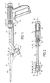
- a prosthesis inserter comprises a main body component 1 having a longitudinal axis and which is the insertion axis, indicated by chain line 2.
- the main body component 1 carries a cranked extension 3 on which is mounted attachment means 4 for holding a femoral prosthesis component indicated by chain lines 5.
- the main body component 1 has a cylindrical support 6 on which is carried a compression spring 7 which bears against a sliding collar 8 also mounted on the cylindrical support 6.
- the collar 8 is provided with a circumferential groove 9 and is connected to an operating rod 10.
- the spring 7 is housed within a casing 11 having a cylindrical bore 12 to enable it to be carried on the cylindrical support 6 and the end of this support has a square section portion 33 and a screw threaded extension 33a on which is located a rotatable locating disc 13 and a screw threaded lock knob 14.
- the end of the bore 12 is of square cross-section to locate on the square section 33 of the support 6.
- the lower part of the casing 11 is extended to form a handle 15 and a guide slot 16 is provided between the handle and the main part of the casing to house a trigger 17.
- the trigger has an upstanding abutment 18 which locates in the annular groove 9 and is also provided with an extension 19 which is shaped to fit into an opening 20 provided on the outer circumference of the disc 13.
- the end of the rod 10 spaced away from the handle 15 is guided in an extended bore 31 located in a projecting boss 21 on the extension 3 and the outer end 22 of the rod 10 is shaped, in this example in the form of a truncated cone, to fit closely into a location feature in the form of a location opening 23 in the prosthesis 5.
- the prosthesis is of modular design, that is a stem component on which heads of different sizes or shapes can be fitted to a spigot 24.
- an adapter 25 is provided which is shown in Figures 4 and 5.
- This adapter can be made from any suitable material, for example metal or a plastics material such as a resilient polycarbonate, and is in the form of a collar 26 one side of which is split to provide an opening 27.
- a pair of claws 28 extend one on each side of the opening 27 and their outer faces 29 are chamfered, as is most clearly shown in Figure 5.
- the internal bore 30 of the collar is slightly less than the outer circumference of the tapered spigot 24 so that it is a push fit onto it, the natural resilience of the material allowing the collar to be placed in position.
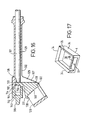
- the attachment means 4 is in the form of a substantially square tray, as is most clearly shown in Figure 17.
- the tray has three upstanding side walls 34 the upper portions of which are chamfered at 35.
- the remaining side is open apart from a bar 36 which extends between the two parallel side walls 34 and leaves beneath it an opening 37 to the flat floor 38 of the tray.
- the angle of the base of the tray is appropriate for the angle of the neck to the stem of the prosthesis to be inserted.
- a collar 25 is first placed over the spigot 24.
- the claws 28 are then pushed into the tray and rotated about the bar 36 so that they extend into the opening 37.
- the dimensions of the claws and the distance from their front faces to the outer circumference of the collar is arranged so that the collar together with the femoral component is locked between the bar 36 and the opposed end wall 34 within the portion of the wall beneath the chamfer 35.
- the width between the parallel walls 34 and the distance between the chamfered faces 29 and the remainder of the walls of the claws relative to the two parallel walls 35 is arranged so that there is a constricting effect tending to close the gap in the collar so that the spigot of the femoral component is tightly clamped.
- the prosthesis is however provided with a location feature in the form of the location opening 23 in the shoulder of the prosthesis.
- the trigger 18 is retracted thus compressing the spring 7 and moving the rod 10 rearwardly. Once the locking pin is approximately in position the trigger can be released and slight further movement will allow the engagement locking pin to move into place.
- the prosthesis is now held by the attachment means 4 and the retractable location means provided by the pin 10 engage the prosthesis at a point spaced away from the attachment means and prevent axial and angular movement in relation to the insertion axis 2 of the inserter.
- the pin 10 is biased into the location opening 23 any downward insertion load by the surgeon whilst the prosthesis is implanted will not be carried by the pin 10 but by the end 32 of the boss 21 bearing against the shoulder of the prosthesis and is also partly carried by the cranked stem 3 which transfers the load to the prosthesis through the attachment means 4.
- the pin 10 merely acts to prevent axial and angular movement.
- the inserter can be removed by one hand, merely be operating the trigger 17 to remove the rod 10 from the location opening 23 to release the location means and by then simply rotating the inserter about the pin 36 so that the attachment means are also released without unnecessarily disturbing the implanted prosthesis and without having to use both hands.
- Figures 7, 8 and 9 show various alternative constructions to provide the location means and which can be employed in any of the constructions described herein.
- Figure 7 shows a construction in which the end of the rod 10 has a single taper 42 and a rounded end 43 which mate with an appropriately shaped opening in the prosthesis 5.
- Figure 8 shows a construction in which the end of the rod has a semi circular shape 44 with an appropriate opening in the prosthesis 5 and Figure 9 shows the end of the rod 10 carrying a bifurcated head 45 which is shaped and dimensioned to fit over the shoulder 46 of the prosthesis 5.
- the location feature is formed by the sides 47 and 48 of the prosthesis.
- the angular position of the handle 15 in relation to the cranked extension 3 can be altered by relocating it on the square section portion 33 of the support 6.
- the lock knob 14 is released by unscrewing it sufficiently to move the casing 11 to the right with respect to the support 6 to disengage the square section.
- the handle is then moved to the desired angular position and slid back onto the square section being subsequently clamped in position by the lock knob 14.
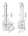
- Figure 6 shows another construction but employing a different form of attachment means.
- a main body 55 carries a hollow extension 56 in which is mounted a retractable rod 57.
- the rod is biased towards a retracted position by a compression spring 58 which acts between the body 55 and an end knob 59.
- the body 55 carries a handle 60 and an operating trigger 61 which is pivoted to the handle by a pin 62.
- the end of the trigger 61 carries a bifurcated arm which surrounds a portion of reduced diameter of the rod (not shown) so that operation of the trigger acts to move the rod in a direction away from the handle and to cause the spring 58 to be compressed.
- the end of the extension 56 spaced away from the handle 60 carries attachment means 63 which are provided by a bracket 64 which is rigidly attached to the extension 56.
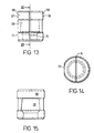
- the other end of the bracket is provided with a socket 65 which is shaped to receive a spigot adapter in the form of a two piece split collet of the kind shown in Figures 13, 14 and 15.
- This collet comprises two collet portions 66 and 67 which are made from a resilient plastics material, for example polypropylene.
- Each of the portions 66, 67 is substantially semi circular and has a closed end provided by an upper wall 68 and a semi circular cavity 69. The cavity is shaped to correspond to the neck 70 and head 71 of the modular prosthesis 72.
- the collet portion 67 has a flat 73 on one side and as will be seen by the drawings each of the collet portions do not extend around a full half circumference of the spigot but leave a gap 74 between them.
- the collet and socket 65 are dimensioned so that the collet and spigot are a push fit into the socket which is sufficient to firmly secure and hold the spigot in place, but allowing the spigot and collet to be easily withdrawn.
- the socket 65 is also provided with a flat 75 on the portion of its wall intended to be adjacent the engagement wall 140 on the locking plate 131 in the construction shown in Figure 10.
- the outer end of the rod 57 carries a shaped end 76 which is adapted to engage in a feature on the shoulder of the prosthesis 72 in a similar manner to the construction shown in Figure 1 but in this construction it will be seen from Figure 6 that the insertion axis 78 is axially aligned with the axis 79 of the prosthesis.
- a split collet of the kind shown in Figures 13, 14 and 15 is first located on the spigot 71 of the prosthesis and is then pushed into the socket 65.
- the shaped end of the rod 57 is extended against the spring 58 by operating the handle 71 so that the end 76 enters the opening in the prosthesis.
- the prosthesis is now firmly attached to the inserter but is prevented from rotating against axial and angular movement in relation to the insertion axis 78.
- any downward insertion load by the surgeon whilst the prosthesis is implanted is partly carried by the rod 57 by the surgeon inserting a pressure on the trigger 61.
- Part of the load can also be carried by the attachment means 63.
- the inserter When the insertion has been completed the inserter can be removed by one hand merely by relieving the pressure on the trigger 61 which allows the location means 76 and 77 to be released and the attachment means can also be released by pulling the socket 65 away from the split collet.
- Figure 10 shows another construction according to the invention which is somewhat similar to that shown in Figure 6 but in which retractable means are included for retaining the collet in place and release means are included for simultaneously actuating the retractable collet retaining means and the retractable location means.
- the device comprises an open framed body 100 in which a sliding rod 101 is mounted.
- the axis of the rod 101 which also forms the insertion axis is indicated by reference numeral 102.
- the rod carries a rigidly attached collar 103 on one side of which is located a compression spring 104 the other end of which bears against the frame of the main body 100 so that the rod is biased towards the right, as shown in the drawing.
- a loosely mounted short spring 105 Located on the other side of the collar 103 is a loosely mounted short spring 105 the operation of which will be described hereafter.
- a third compression spring 106 is also carried on the rod one end of which bears against a frame member 107 and the other end of which acts against an actuator 108 which is also carried on the rod and is in the form of a plate the upper end of which is provided with a slot 109 which can slide along a guide 110 in the upper part of the body frame.
- the lower part of the actuator 108 is cut away to provide a further guide surface 111 which can slide along a lower frame portion 112.
- a first operating trigger 113 is also carried on the lower frame 112 by a pivot 114.
- the lower part of the first trigger 113 is formed as an operating lever 115 and the upper part 116 is shaped to engage the lower part of the actuator 108.
- An extension of the lower part of the frame 112 is shaped to form a handle 117 on which is pivoted a second operating lever 118 the upper part of which is in the form of a hook 119 which engages the lower part of a locking member 120.
- the locking member is freely mounted on the rod 101 and the upper part is provided with a yoke 121 which engages on both sides of a retaining ridge 122 on the main body 100.
- a fourth compression spring 123 is carried on the rod 101 between a rear frame member 124 through which the rod 101 passes and the locking member 120.
- the rod 101 passes from the body 100 through a tubular extension 125 and emerges as a locating pin 126 which provides locating means.
- a bracket 127 is carried on the end of the extension 125, and has a socket 128 which forms part of the attachment means.
- the construction of the attachment means is most clearly shown in Figures 11 and 12.
- the side of the socket 128 is cut away to provide a slot 129 which extends through the bracket 127 and into the cylindrical extension 125 as indicated by reference numeral 130.
- Collet retaining means are provided in the form of a collet lock provided by a flat locking plate 131 which is located in the slot 129 and pivoted by a pin 132.
- the locking plate is bifurcated at 133 to provide a pair of arms which pass each side of a reduced portion 134 of the rod 101.
- the reduced portion 134 terminates at one end in an abutment ridge 135 and at the other in an enlargement 136 as is most clearly shown in Figure 11.
- the locking plate 131 also carries a locking hook 137 having an engagement face 138 and an engagement wall 140.
- the socket 128 is dimensioned to receive a split collet of the type shown in Figures 13, 14 and 15.
- the opening in the locking member 120 is slightly larger than the diameter of the operating rod 101 but because the spring 123 pushes the lever outwardly away from the frame member 124 the lever tends to rotate about the retaining ridge 122 so that the opening operates to jam against the rod 101 and prevent movement.
- the second operating lever 118 When the second operating lever 118 is operated it rotates and the hook 119 presses against the lower end of the locking lever so that it rotates against the action of the spring 123 and thus frees the rod 101.
- the actuator plate 108 is a loose fit on the rod 101 so that although it can tilt under the action of the trigger 113 it then locks onto the rod 101 and acts to move it against the action of the third spring 106.
- the trigger can move the actuating plate to provide an "inching" movement or as a single or separate movements to advance the rod to the operating position.
- the third spring 106 pushes the actuating plate 101 to the position shown in Figure 10 so that the plate always returns to this position after use of the trigger irrespective of the position of the rod 101.
- the two piece collet 68 is first placed in position on the neck and tapered spigot of the prosthesis. With the rod 101 in the retracted position the collet and prosthesis are inserted into the socket 128 and the first trigger is operated to move the rod 101 into its operative position with the locating pin entering a suitable opening in the prosthesis and the hook 137 engaging over the end of the collet, at the same time the collet is slightly compressed to hold it firmly in the socket by the wall 140.
- the prosthesis can now be inserted by the surgeon holding the handle 117 and once the insertion has been completed the inserter can simply be removed by one hand by operating the lever 118 which releases both the locating means and the attachment means provided by the locking hook 137 and wall 140 acting on the collet. With these released the inserter can be easily removed, the whole operation being carried out by one hand.
- Figure 16 shows another construction according to the invention which is somewhat similar to that shown in Figures 10 to 15 but in which the location means does not retract.
- the same reference numerals are used to indicate similar parts to those shown in Figures 10 to 12 and a split collet similar to that shown in Figures 13 to 15 is employed.
- rod 101 is provided with a groove 150 and the outer end 151 of the rod is carried in a blind bore 152 provided in a housing 153.
- This housing is screw threaded at 154 into the outer end of the tubular extension 125.
- the housing is shaped to provide a locating pin 155 which is appropriately shaped to engage a suitable opening in the prosthesis.
- a locating pin 155 which is appropriately shaped to engage a suitable opening in the prosthesis.
- the bifurcated part 133 of the locking plate which provides the pair of arms engage in the groove 150 and are acted upon by the abutment ridge 135 provided by one side of the groove.
- a second abutment ridge 156 provided by the other side of the groove.
- the triggers 113 and 117 are operated in a similar manner to that described with regard to Figures 10 to 12 but it will be seen that when the rod 101 is advanced it only operates on the locking plate 131, the outer end 151 of the rod 101 sliding in the blind bore 152. Retracting of the locking plate 131 is again achieved in a similar manner to operation of the construction shown in Figures 10 to 12 but in this case the second abutment ridge 156 acts against the bifurcation 133 to move the locking plate 131 to its retracted position.
- This construction is used in a similar manner to that described with regard to Figures 10 to 12 but in this case the location means provided by the location pin 155 is pushed into position and the trigger 113 is operated to lock the spigot into the attachment means. In order to remove the inserter the trigger 118 is operated to release the locking plate 131 so that the inserter can be removed.
- locating means can be employed, for example as shown in Figures 7, 8 and 9, there are others which could be equally effective.
- a locating means can be used which only engages one side wall of the prosthesis to be inserted, the device employing a flat surface which has sufficient length to effectively prevent angular rotation of the prosthesis about its spigot in both directions.
- a prosthesis inserter comprises a prosthesis holder which includes a tubular main body component 20 having a longitudinal axis co-axial with the insertion axis the distal end of which is attached by a fixing screw 215 which bears on a section of reduced diameter 216 to an operating handle 202.
- the handle 202 houses a pivotal lever 203 which rotates around pivot 214, and one end of which bears upon one end of an operating rod 204 which can travel along the insertion axis.
- the operating rod 204 is mounted coaxially with the main body component 201 in a bore and a spring 205 is provided between the distal end of the operating arm and the distal end of the main body component 201 to bias the rod 204 towards a rest position.
- the proximal end of the operating rod arm 204 has a shaped end 206 of reduced diameter for limited insertion into the femoral prosthesis 207.
- the proximal end of the main body component 201 has tapered flats 208 to produce a tapering effect when inserted into a tapered socket 210 of an attachment element 209 the flats precluding torsional movement of the main body component 201 in the element 209.
- the tapered socket 210 allows limited entry of the main body component 201 while allowing full passage of the operating rod 204.
- the attachment element 209 also has an additional tapered socket 211 which fits over the tapered spigot 212 of the femoral prosthesis 207 to co-operate therewith and to firmly locate thereon.
- An engagement feature 213 is provided on the shoulder of the prosthesis 207 for locating the shaped end of the operating rod 204 so that when engaged if ensures that the entire assembly is held rigid.
- the parts are assembled by firstly firmly inserting the tapered spigot 212 of the femoral prosthesis 207 into the tapered socket 211 of the attachment element 209, then by firmly inserting the tapered end 208 of the tubular main body component into the tapered socket 210 of the attachment element 209 and the shaped end 206 of the operating rod 204 into the engagement feature 213 of the prosthesis 207.
- the pivotal lever 203 is rotated about the pivot 214 which causes one end of the lever to bear upon the distal end of the operating rod.
- This causes the spring 205 to be compressed allowing the operating rod 204 to travel within the tubular main body component 201.
- the shaped end 206 of the operating rod 204 is now caused to bear upon the femoral prosthesis 207 to release the tubular main body component 201 from the attachment element 209 and allowing the attachment element 209 to be released from the tapered spigot 212 of the femoral prosthesis 207.
- FIGS 23 and 24 show an alternative construction of attachment element indicated by reference numeral 230.
- the same reference numerals are used to indicate similar parts to those shown in Figures 18 to 22 but in this arrangement the tapered sockets 210 and 211 are interconnected by a bridge 231 which has a slight amount of flexibility.
- the slight amount of flexibility allows the front face 232 of the portion providing the socket 210 to bear against the shoulder of the prosthesis and when the rod 204 is released to move away thus facilitating release.
- FIG. 23 and 24 The construction shown in Figures 23 and 24 is also provided with a pair of spaced apart wings 233 to allow the connection of means to control the position and depth of the prosthesis when it is placed in position with respect to the bone into which it is to be inserted in the manner described in the Applicant's copending British Patent Application GB-A-9804471.2 (H.67).
- Figure 25 shows another construction of attachment element, indicated by reference numeral 240, which is similar to that shown in Figures 23 and 24 but in which the wings 233 are not included and the closed end of the socket 210 is deleted.
- the socket is replaced by a tapered bore 241 so that the end of the main body component 201 can pass through it and directly engage the shoulder of the prosthesis 212.
- advantages with this construction in as much that axial forces applied by the handle through the main body component 201 can be directly transferred to the shoulder of the prosthesis.
- the apparatus works in the same way as that described with regard to the other constructions.
Claims (21)
- Prothesenimplantations-Einsetzvorrichtung zum Einsetzen einer mit einem überstehenden Zapfen (24) versehenen Prothese (5), umfassend eine Befestigungseinrichtung (4) zur Befestigung am Prothesenzapfen (24) sowie eine Positioniereinrichtung (10)(22), die im Abstand von der Befestigungseinrichtung (4) angeordnet und angepasst ist, um mit der Prothese (5) lösbar in Eingriff zu treten, um eine Axial- und Winkelbewegung derselben in Bezug zur Einführachse (2) der Einsetzvorrichtung zu verhindern, wobei die Befestigungseinrichtung (4) den besagten Zapfen (24) umgibt, um die Prothese an der Einsetzvorrichtung zu befestigen, gekennzeichnet durch einen Griff (15) zum Festhalten der Einsetzvorrichtung in einer Hand, um ein Einsetzen der Prothese (5) durch einhändige Bedienung zu ermöglichen, sowie eine Freigabeeinrichtung (17) zum Lösen der Prothese von der Positioniereinrichtung, wobei sich die Freigabeeinrichtung zwischen dem Griff und der Positioniereinrichtung (10)(22) erstreckt und mittels derselben Hand, die den Griff hält, einhändig bedienbar ist, um die Positioniereinrichtung (10)(22) und die Befestigungseinrichtung (4) freizugeben.
- Prothesenimplantations-Einsetzvorrichtung nach Anspruch 1, dadurch gekennzeichnet, dass auf die Einsetzvorrichtung aufgebrachte Implantationsbelastungen durch die Befestigungseinrichtung (4) auf die zu implantierende Prothese (15) übertragen werden.
- Prothesenimplantations-Einsetzvorrichtung nach Anspruch 1, dadurch gekennzeichnet, dass auf die Einsetzvorrichtung aufgebrachte Implantationsbelastungen durch die Positioniereinrichtung (57)(76) auf die zu implantierende Prothese übertragen werden.
- Prothesenimplantations-Einsetzvorrichtung nach einem der Ansprüche 1 bis 3, dadurch gekennzeichnet, dass die Befestigungseinrichtung (4) einen elastischen Adapter (25) einschließt, der so geformt ist, dass er den Kopfzapfen (24) der zu implantierenden Prothese (5) umgibt, sowie die Bereitstellung von Eingriffseinrichtungen (35)(34)(36), die den elastischen Adapter (25) festhalten.
- Prothesenimplantations-Einsetzvorrichtung nach Anspruch 4, dadurch gekennzeichnet, dass der elastische Adapter (25) eine Eingriffsklaue oder -klauen (28) einschließt, die sich in den Eingriffseinrichtungen (34)(35)(36) positionieren.
- Prothesenimplantations-Einsetzvorrichtung nach Anspruch 4, dadurch gekennzeichnet, dass der elastische Adapter (25) in Form einer Hülse (66)(67) vorliegt, die einen Flansch aufweist, der angepasst ist, um unter dem Kopfzapfen der zu implantierenden Prothese in Eingriff zu treten, sowie lösbare Einrichtungen (131)(137), um die Hülse (66)(67) an ihrem Platz festzuhalten.
- Prothesenimplantations-Einsetzvorrichtung nach Anspruch 6, dadurch gekennzeichnet, dass die Hülse (66)(67) zweigeteilt ist.
- Prothesenimplantations-Einsetzvorrichtung nach Anspruch 6 oder Anspruch 7, dadurch gekennzeichnet, dass sie Betätigungseinrichtungen (101)(125)(113)(118) einschließt, um die Festhalteeinrichtungen (131)(137) für die lösbare Hülse und die Positioniereinrichtungen (126) gleichzeitig zu betätigen.
- Prothesenimplantations-Einsetzvorrichtung nach einem der vorangehenden Ansprüche, dadurch gekennzeichnet, dass die Befestigungseinrichtung ein Befestigungselement (209) einschließt, das angepasst ist, um es am Kopf zapfen (212) der femoralen Komponente (207) zu befestigen, und um auch die Positioniereinrichtung (206) aufzunehmen.
- Prothesenimplantations-Einsetzvorrichtung nach Anspruch 9, dadurch gekennzeichnet, dass das Befestigungselement (209) Einrichtungen (210) zur festen Befestigung an der Einsetzvorrichtung aufweist.
- Prothesenimplantations-Einsetzvorrichtung nach Anspruch 10, dadurch gekennzeichnet, dass das Befestigungselement (209) eine verjüngte Buchse (211) aufweist, die bemessen ist, um mit dem Zapfen (212) der Prothese (207) zusammenzuwirken, sowie eine verjüngte Buchse (210), um mit einem geeigneten Teil (208) der Einsetzvorrichtung benachbart zur Positioniereinrichtung (206) zusammenzuwirken.
- Prothesenimplantations-Einsetzvorrichtung nach den Ansprüchen 9 bis 11, dadurch gekennzeichnet, dass das Befestigungselement (209) angepasst ist, um mit einer proximalen Schulter der zu implantierenden femoralen Komponente (207) in Eingriff zu treten.
- Prothesenimplantations-Einsetzvorrichtung nach einem der vorangehenden Ansprüche 9 bis 12, dadurch gekennzeichnet, dass das Befestigungselement (204) aus einem synthetischen Kunststoffmaterial hergestellt ist.
- Prothesenimplantations-Einsetzvorrichtung nach Anspruch 13, dadurch gekennzeichnet, dass das synthetische Kunststoffmaterial Polycarbonat ist.
- Prothesenimplantations-Einsetzvorrichtung nach einem der vorangehenden Ansprüche 1 bis 11, dadurch gekennzeichnet, dass die Positioniereinrichtung (10)(22) (126)(206) angepasst ist, um mit einem Positioniermerkmal (23) auf der zu implantierenden Prothese (5)(72) in Eingriff zu treten.
- Prothesenimplantations-Einsetzvorrichtung nach Anspruch 15, dadurch gekennzeichnet, dass das Positioniermerkmal (23) von einer Seite oder Seiten der Prothese bereitgestellt wird.
- Prothesenimplantations-Einsetzvorrichtung nach Anspruch 16, dadurch gekennzeichnet, dass die Positioniereinrichtung einen zurückziehbaren Gabelteil (45)(46) einschließt, der mit den Seiten der Prothese in Eingriff tritt.
- Prothesenimplantations-Einsetzvorrichtung nach Anspruch 15, dadurch gekennzeichnet, dass die Positioniereinrichtung einen zurückziehbaren Bolzen (10) einschließt, der angepasst ist, um mit einer Positionieröffnung in der Prothese in Eingriff zu treten.
- Prothesenimplantations-Einsetzvorrichtung nach Anspruch 17 oder Anspruch 18, dadurch gekennzeichnet, dass Einrichtungen (9)(18) eingeschlossen sind, um die zurückziehbare Positioniereinrichtung (10) in einer zurückgezogenen Position zu halten.
- Prothesenimplantations-Einsetzvorrichtung nach einem der vorangehenden Ansprüche 1 bis 19, dadurch gekennzeichnet, dass sie einen Körperteil (11), der sich entlang der Einführachse (7) erstreckt, einen Griff (15), sowie einen Auslöser (17) zur Betätigung der zurückziehbaren Positioniereinrichtungen (10) einschließt.
- Prothesenimplantations-Einsetzvorrichtung nach Anspruch 20, dadurch gekennzeichnet, dass der Auslöser (17) dazu dienen kann, die Befestigungseinrichtung (4) freizugeben und die Positioniereinrichtung (10) zurückzuziehen.
Applications Claiming Priority (4)
| Application Number | Priority Date | Filing Date | Title |
|---|---|---|---|
| GB9804471 | 1998-03-02 | ||
| GBGB9804471.2A GB9804471D0 (en) | 1998-03-02 | 1998-03-02 | Prosthesis inserter |
| GBGB9825939.3A GB9825939D0 (en) | 1998-11-26 | 1998-11-26 | Prosthesis inserter |
| GB9825939 | 1998-11-26 |
Publications (3)
| Publication Number | Publication Date |
|---|---|
| EP0940127A2 EP0940127A2 (de) | 1999-09-08 |
| EP0940127A3 EP0940127A3 (de) | 2000-11-02 |
| EP0940127B1 true EP0940127B1 (de) | 2003-11-26 |
Family
ID=26313211
Family Applications (1)
| Application Number | Title | Priority Date | Filing Date |
|---|---|---|---|
| EP99301387A Expired - Lifetime EP0940127B1 (de) | 1998-03-02 | 1999-02-25 | Prothesen-Einsetzvorrichtung |
Country Status (4)
| Country | Link |
|---|---|
| US (1) | US6113605A (de) |
| EP (1) | EP0940127B1 (de) |
| JP (1) | JP4278216B2 (de) |
| DE (1) | DE69913012T2 (de) |
Cited By (1)
| Publication number | Priority date | Publication date | Assignee | Title |
|---|---|---|---|---|
| US7780673B2 (en) | 2000-04-26 | 2010-08-24 | Zimmer Technology, Inc. | Method and apparatus for performing a minimally invasive total hip arthroplasty |
Families Citing this family (67)
| Publication number | Priority date | Publication date | Assignee | Title |
|---|---|---|---|---|
| CA2362792A1 (en) * | 1999-03-03 | 2000-09-08 | Smith & Nephew, Inc. | Methods, systems, and instruments for inserting prosthetic implants |
| AU781109B2 (en) * | 2000-03-02 | 2005-05-05 | Smith & Nephew, Inc. | Shrouds for implants |
| US20050043810A1 (en) * | 2000-04-26 | 2005-02-24 | Dana Mears | Method and apparatus for performing a minimally invasive total hip arthroplasty |
| US6676706B1 (en) | 2000-04-26 | 2004-01-13 | Zimmer Technology, Inc. | Method and apparatus for performing a minimally invasive total hip arthroplasty |
| US7001333B2 (en) | 2000-12-20 | 2006-02-21 | Hamel Ross J | Surgical retractor system |
| JP2003185767A (ja) * | 2001-12-21 | 2003-07-03 | Seiko Instruments Inc | 電子潮汐計、満潮干潮時刻算出方法、及び、その方法を実行するプログラムの格納媒体 |
| US7799086B2 (en) * | 2002-04-25 | 2010-09-21 | Zimmer Technology, Inc. | Modular bone implant, tools, and method |
| US7122048B2 (en) * | 2002-05-03 | 2006-10-17 | Scimed Life Systems, Inc. | Hypotube endoluminal device |
| US7572276B2 (en) | 2002-05-06 | 2009-08-11 | Warsaw Orthopedic, Inc. | Minimally invasive instruments and methods for inserting implants |
| US7037311B2 (en) * | 2002-07-12 | 2006-05-02 | Zimmer Technology, Inc. | Tool for gripping an orthopedic implant |
| US7235106B2 (en) * | 2002-12-20 | 2007-06-26 | Depuy Products, Inc. | Modular hip stems and associated method of trialing |
| US7022141B2 (en) * | 2002-12-20 | 2006-04-04 | Depuy Products, Inc. | Alignment device for modular implants and method |
| US7854737B2 (en) | 2002-12-20 | 2010-12-21 | Depuy Products, Inc. | Instrument and associated method of trailing for modular hip stems |
| US7252673B2 (en) * | 2003-09-10 | 2007-08-07 | Warsaw Orthopedic, Inc. | Devices and methods for inserting spinal implants |
| EP1696807B1 (de) * | 2003-11-18 | 2009-09-30 | Smith & Nephew, Inc. | Operationstechnik und instrumente für die minimalinzisions-hüft-arthoplastiechirurgie |
| US7341587B2 (en) * | 2003-11-20 | 2008-03-11 | Warsaw Orthopedic, Inc. | Methods and devices for inserting and engaging vertebral implants in minimally invasive procedures |
| US8123757B2 (en) | 2003-12-31 | 2012-02-28 | Depuy Spine, Inc. | Inserter instrument and implant clip |
| US20050203539A1 (en) * | 2004-03-08 | 2005-09-15 | Grimm James E. | Navigated stemmed orthopaedic implant inserter |
| US7481813B1 (en) * | 2004-11-19 | 2009-01-27 | Alphatec Spine, Inc. | Securing device and corresponding methods thereof for bone fixation systems |
| CH697839B1 (it) * | 2005-01-28 | 2009-02-27 | Gen East Licence Kft | Insieme di raspa e dispositivo introduttore-estrattore. |
| US20060200162A1 (en) * | 2005-02-21 | 2006-09-07 | Zimmer Technology, Inc. | Total knee arthroplasty instruments |
| US7708743B2 (en) * | 2005-04-29 | 2010-05-04 | Warsaw Orthopedic, Inc. | Apparatus and method for positioning an implant during surgery |
| DE202005014270U1 (de) * | 2005-09-09 | 2007-01-11 | Waldemar Link Gmbh & Co. Kg | Einsetzinstrument für eine Endoprothese mit einem in einem Markraum einzusetzenden Prothesenschaft |
| US20070093897A1 (en) * | 2005-10-21 | 2007-04-26 | Stryker Spine (In France) | System and method for fusion cage implantation |
| EP1787603A1 (de) | 2005-11-18 | 2007-05-23 | Zimmer GmbH | Basisplattform für ein künstliches Gelenk |
| US7867279B2 (en) * | 2006-01-23 | 2011-01-11 | Depuy Spine, Inc. | Intervertebral disc prosthesis |
| US7621921B2 (en) * | 2006-01-25 | 2009-11-24 | Symmetry Medical, Inc | Split thread orthopaedic implant impactor |
| US8303601B2 (en) | 2006-06-07 | 2012-11-06 | Stryker Spine | Collet-activated distraction wedge inserter |
| US20080133023A1 (en) * | 2006-10-05 | 2008-06-05 | Zimmer Technology, Inc. | Provisional prosthetic component formed of multiple materials |
| US20080161821A1 (en) * | 2006-10-16 | 2008-07-03 | Warsaw Orthopedic, Inc. | Surgical Tool for Insertion of Spinal Prosthesis |
| US20080255565A1 (en) * | 2006-11-20 | 2008-10-16 | Fletcher Henry H | Broach handle for minimally invasive hip replacement surgery |
| US20080255574A1 (en) * | 2007-04-13 | 2008-10-16 | Zimmer Technology, Inc. | Instrument for insertion of prosthetic components |
| US20080269765A1 (en) * | 2007-04-27 | 2008-10-30 | Zimmer, Inc. | Instrument and method for implanting a prosthetic component |
| US8579910B2 (en) * | 2007-05-18 | 2013-11-12 | DePuy Synthes Products, LLC | Insertion blade assembly and method of use |
| US20090099566A1 (en) * | 2007-10-10 | 2009-04-16 | Maness Megan A | Modular stem inserter |
| US8142441B2 (en) * | 2008-10-16 | 2012-03-27 | Aesculap Implant Systems, Llc | Surgical instrument and method of use for inserting an implant between two bones |
| US8591587B2 (en) | 2007-10-30 | 2013-11-26 | Aesculap Implant Systems, Llc | Vertebral body replacement device and method for use to maintain a space between two vertebral bodies within a spine |
| US8182537B2 (en) | 2007-10-30 | 2012-05-22 | Aesculap Implant Systems, Llc | Vertebral body replacement device and method for use to maintain a space between two vertebral bodies within a spine |
| US8142435B2 (en) | 2009-02-19 | 2012-03-27 | Aesculap Implant Systems, Llc | Multi-functional surgical instrument and method of use for inserting an implant between two bones |
| US8906033B2 (en) | 2009-03-30 | 2014-12-09 | DePuy Synthes Products, LLC | Cervical motion disc inserter |
| US8449548B2 (en) * | 2009-12-22 | 2013-05-28 | Howmedica Osteonics Corp. | Broach handle with flexure spring |
| GB201011035D0 (en) * | 2010-07-01 | 2010-08-18 | Finsbury Dev Ltd | An impactor |
| US11484627B2 (en) | 2010-10-20 | 2022-11-01 | 206 Ortho, Inc. | Method and apparatus for treating bone fractures, and/or for fortifying and/or augmenting bone, including the provision and use of composite implants, and novel composite structures which may be used for medical and non-medical applications |
| EP2629780A4 (de) | 2010-10-20 | 2014-10-01 | 206 Ortho Inc | Implantierbares polymer für knochen- und gefässläsionen |
| US11058796B2 (en) | 2010-10-20 | 2021-07-13 | 206 Ortho, Inc. | Method and apparatus for treating bone fractures, and/or for fortifying and/or augmenting bone, including the provision and use of composite implants, and novel composite structures which may be used for medical and non-medical applications |
| US11291483B2 (en) | 2010-10-20 | 2022-04-05 | 206 Ortho, Inc. | Method and apparatus for treating bone fractures, and/or for fortifying and/or augmenting bone, including the provision and use of composite implants |
| US9320601B2 (en) | 2011-10-20 | 2016-04-26 | 206 Ortho, Inc. | Method and apparatus for treating bone fractures, and/or for fortifying and/or augmenting bone, including the provision and use of composite implants |
| US11207109B2 (en) | 2010-10-20 | 2021-12-28 | 206 Ortho, Inc. | Method and apparatus for treating bone fractures, and/or for fortifying and/or augmenting bone, including the provision and use of composite implants, and novel composite structures which may be used for medical and non-medical applications |
| US10525169B2 (en) | 2010-10-20 | 2020-01-07 | 206 Ortho, Inc. | Method and apparatus for treating bone fractures, and/or for fortifying and/or augmenting bone, including the provision and use of composite implants, and novel composite structures which may be used for medical and non-medical applications |
| WO2015095745A1 (en) | 2010-10-20 | 2015-06-25 | 206 Ortho, Inc. | Method and apparatus for treating bone fractures, and/or for fortifying and/or augmenting bone, including the provision and use of composite implants, and novel composite structures which may be used for medical and non-medical applications |
| US9339393B2 (en) * | 2011-03-28 | 2016-05-17 | Zimmer, Inc. | Orthopedic implant insertion instrument |
| US9220611B2 (en) | 2011-07-12 | 2015-12-29 | Zimmer, Inc. | Femoral component instrument |
| US9011450B2 (en) | 2012-08-08 | 2015-04-21 | DePuy Synthes Products, LLC | Surgical instrument |
| US9084685B2 (en) * | 2012-09-28 | 2015-07-21 | DePuy Synthes Products, Inc. | Femoral prosthesis with insertion/extraction feature |
| US10010609B2 (en) | 2013-05-23 | 2018-07-03 | 206 Ortho, Inc. | Method and apparatus for treating bone fractures, and/or for fortifying and/or augmenting bone, including the provision and use of composite implants |
| US9867628B2 (en) * | 2013-11-07 | 2018-01-16 | Zimmer, Inc. | Device for extraction of prosthetic implants |
| US10456264B2 (en) | 2014-01-24 | 2019-10-29 | Tornier, Inc. | Humeral implant anchor system |
| US10575968B2 (en) * | 2014-05-16 | 2020-03-03 | Howmedica Osteonics Corp. | Guides for fracture system |
| WO2016113539A1 (en) | 2015-01-15 | 2016-07-21 | Depuy (Ireland) | Assembly tool |
| US9937048B2 (en) * | 2015-01-15 | 2018-04-10 | Depuy Ireland Unlimited Company | Femoral stem including an anchor to facilitate assembly and implantation |
| US10219810B2 (en) * | 2015-02-16 | 2019-03-05 | Warsaw Orthopedic, Inc. | Surgical instrument system and method |
| US10463499B2 (en) | 2016-03-25 | 2019-11-05 | Tornier, Inc. | Stemless shoulder implant with fixation components |
| WO2018022227A1 (en) | 2016-07-28 | 2018-02-01 | Tornier, Inc. | Stemless prosthesis anchor component |
| DE102017101191A1 (de) * | 2017-01-23 | 2018-07-26 | Aesculap Ag | Hüftgelenkendoprothesensystem |
| CN110234288B (zh) | 2017-02-01 | 2022-05-06 | 捷迈有限公司 | 胫骨托撞击器 |
| US11207197B2 (en) | 2019-08-01 | 2021-12-28 | DePuy Synthes Products, Inc. | Orthopaedic surgical instrument for total hip arthroplasty and associated orthopaedic surgical method of use |
| CN114502106A (zh) * | 2019-10-01 | 2022-05-13 | 赫迈迪卡奥斯特尼克斯公司 | 肩假体部件和组件 |
Family Cites Families (14)
| Publication number | Priority date | Publication date | Assignee | Title |
|---|---|---|---|---|
| US3857389A (en) * | 1973-06-06 | 1974-12-31 | H Amstutz | Prosthesis holder |
| FR2583635B1 (fr) * | 1985-06-24 | 1990-04-27 | Ouest Equip Medical Chirurgica | Instrument porte-prothese |
| FR2615097B1 (fr) * | 1987-05-12 | 1989-08-18 | Landos Applic Orthopediques Fs | Impacteur-extracteur de prothese notamment de hanche |
| FR2627983B1 (fr) * | 1988-03-02 | 1997-05-16 | Vecteur Orthopedic Sa | Dispositif de mise en place de protheses femorales de hanches |
| US4936863A (en) * | 1988-05-13 | 1990-06-26 | Hofmann Aaron A | Hip prosthesis |
| US4993410A (en) * | 1989-05-01 | 1991-02-19 | Kimsey Timothy P | Prosthetic removal device |
| US5064427A (en) * | 1991-05-14 | 1991-11-12 | Intermedics Orthopedics, Inc. | Apparatus for inserting and withdrawing humeral prosthesis |
| DE4220970A1 (de) * | 1991-12-30 | 1993-07-01 | Artos Med Produkte | Ausschlaginstrument |
| US5443471A (en) * | 1993-02-16 | 1995-08-22 | Howmedica, Inc. | Quick release handle assembly |
| DE4332872C1 (de) * | 1993-09-27 | 1995-04-06 | Zsolt Szabo | Ausschlagwerkzeug für Gelenkprothesen |
| DE59409052D1 (de) * | 1994-04-25 | 2000-02-10 | Sulzer Orthopaedie Ag Baar | Ausziehinstrument für einen Schaft einer Hüftgelenkprothese oder einer entsprechenden Raspel |
| GB2307861B (en) * | 1995-12-08 | 1999-12-01 | Corin Medical Ltd | Surgical instrument and prosthesis combination |
| FR2742334B1 (fr) * | 1995-12-18 | 1998-05-15 | Maurice Lanzoni | Dispositif developpeur d'effort d'un prehenseur universel de tige femorale |
| US5989259A (en) * | 1998-08-25 | 1999-11-23 | Johnson & Johnson Professional, Inc. | Femoral calcar stop for use with femoral stem inserter |
-
1999
- 1999-02-25 DE DE69913012T patent/DE69913012T2/de not_active Expired - Lifetime
- 1999-02-25 US US09/257,306 patent/US6113605A/en not_active Expired - Lifetime
- 1999-02-25 EP EP99301387A patent/EP0940127B1/de not_active Expired - Lifetime
- 1999-03-02 JP JP05467299A patent/JP4278216B2/ja not_active Expired - Fee Related
Cited By (1)
| Publication number | Priority date | Publication date | Assignee | Title |
|---|---|---|---|---|
| US7780673B2 (en) | 2000-04-26 | 2010-08-24 | Zimmer Technology, Inc. | Method and apparatus for performing a minimally invasive total hip arthroplasty |
Also Published As
| Publication number | Publication date |
|---|---|
| JP4278216B2 (ja) | 2009-06-10 |
| US6113605A (en) | 2000-09-05 |
| DE69913012D1 (de) | 2004-01-08 |
| EP0940127A3 (de) | 2000-11-02 |
| JPH11313841A (ja) | 1999-11-16 |
| DE69913012T2 (de) | 2004-04-15 |
| EP0940127A2 (de) | 1999-09-08 |
Similar Documents
| Publication | Publication Date | Title |
|---|---|---|
| EP0940127B1 (de) | Prothesen-Einsetzvorrichtung | |
| US6110179A (en) | Prosthesis inserter | |
| US5443471A (en) | Quick release handle assembly | |
| US5116339A (en) | Acetabular cup installation tool and method of installing an acetabular cup | |
| EP0535973B1 (de) | Vorrichtung zum Einsetzen einer Hüftpfannenprothese | |
| US7037311B2 (en) | Tool for gripping an orthopedic implant | |
| US4716894A (en) | Acetabular cup inserting instrument | |
| US5431660A (en) | Spring loaded screw and driver/extractor therefor | |
| US5462548A (en) | Acetabular reamer | |
| US20040010261A1 (en) | Tool for releasably gripping an orthopedic implant | |
| EP0880340B1 (de) | Instrument zum einsetzen einer hüftprothese | |
| CA2195269C (en) | Bone anchor inserter, method for loading same, method for holding and delivering a bone anchor, and method for inserting a bone anchor in a bone | |
| US6193759B1 (en) | Modular long stem hip trial | |
| US4587964A (en) | Rasp tool | |
| US5089003A (en) | Rasp tool including detachable handle member | |
| US5849015A (en) | Orthopaedic stem inserter with quick release lever and ratchet | |
| JPH06319761A (ja) | 人工関節の骨頭を備える移植組織の移植用環状骨準備装置 | |
| US6080162A (en) | Modular orthopaedic clamping tool | |
| US5928287A (en) | Acetabular cup and surgical instrument for implanting same | |
| USRE43526E1 (en) | Rod introduction apparatus | |
| US4919679A (en) | Femoral stem surgical instrument system | |
| CA2499337C (en) | Prosthetic acetabular cup inserter | |
| JPH09289997A (ja) | 人工膝関節埋め込み工具システムおよびユニバーサル手具 | |
| GB2307861A (en) | Prosthesis holding device | |
| US6022355A (en) | Impaction hammer for bone chips |
Legal Events
| Date | Code | Title | Description |
|---|---|---|---|
| PUAI | Public reference made under article 153(3) epc to a published international application that has entered the european phase |
Free format text: ORIGINAL CODE: 0009012 |
|
| AK | Designated contracting states |
Kind code of ref document: A2 Designated state(s): CH DE FR GB IT LI |
|
| AX | Request for extension of the european patent |
Free format text: AL;LT;LV;MK;RO;SI |
|
| PUAL | Search report despatched |
Free format text: ORIGINAL CODE: 0009013 |
|
| AK | Designated contracting states |
Kind code of ref document: A3 Designated state(s): AT BE CH CY DE DK ES FI FR GB GR IE IT LI LU MC NL PT SE |
|
| AX | Request for extension of the european patent |
Free format text: AL;LT;LV;MK;RO;SI |
|
| 17P | Request for examination filed |
Effective date: 20001120 |
|
| AKX | Designation fees paid |
Free format text: CH DE FR GB IT LI |
|
| RAP1 | Party data changed (applicant data changed or rights of an application transferred) |
Owner name: BENOIST GIRARD SAS |
|
| 17Q | First examination report despatched |
Effective date: 20020923 |
|
| GRAH | Despatch of communication of intention to grant a patent |
Free format text: ORIGINAL CODE: EPIDOS IGRA |
|
| GRAS | Grant fee paid |
Free format text: ORIGINAL CODE: EPIDOSNIGR3 |
|
| GRAA | (expected) grant |
Free format text: ORIGINAL CODE: 0009210 |
|
| AK | Designated contracting states |
Kind code of ref document: B1 Designated state(s): CH DE FR GB IT LI |
|
| REG | Reference to a national code |
Ref country code: GB Ref legal event code: FG4D |
|
| REG | Reference to a national code |
Ref country code: CH Ref legal event code: EP |
|
| REG | Reference to a national code |
Ref country code: CH Ref legal event code: NV Representative=s name: BOVARD AG PATENTANWAELTE |
|
| REF | Corresponds to: |
Ref document number: 69913012 Country of ref document: DE Date of ref document: 20040108 Kind code of ref document: P |
|
| ET | Fr: translation filed | ||
| PLBE | No opposition filed within time limit |
Free format text: ORIGINAL CODE: 0009261 |
|
| STAA | Information on the status of an ep patent application or granted ep patent |
Free format text: STATUS: NO OPPOSITION FILED WITHIN TIME LIMIT |
|
| 26N | No opposition filed |
Effective date: 20040827 |
|
| REG | Reference to a national code |
Ref country code: FR Ref legal event code: TP Owner name: STRYKER IRELAND LIMITED, IE Effective date: 20130305 |
|
| REG | Reference to a national code |
Ref country code: DE Ref legal event code: R082 Ref document number: 69913012 Country of ref document: DE Representative=s name: MAIWALD GMBH PATENTANWAELTE, DE Effective date: 20130215 Ref country code: DE Ref legal event code: R081 Ref document number: 69913012 Country of ref document: DE Owner name: STRYKER IRELAND LTD., CARRIGTWOHILL, IE Free format text: FORMER OWNER: BENOIST GIRARD SAS, HEROUVILLE SAINT CLAIR, FR Effective date: 20130215 Ref country code: DE Ref legal event code: R081 Ref document number: 69913012 Country of ref document: DE Owner name: STRYKER IRELAND LTD., IE Free format text: FORMER OWNER: BENOIST GIRARD SAS, HEROUVILLE SAINT CLAIR, FR Effective date: 20130215 |
|
| PGFP | Annual fee paid to national office [announced via postgrant information from national office to epo] |
Ref country code: CH Payment date: 20130129 Year of fee payment: 15 |
|
| REG | Reference to a national code |
Ref country code: GB Ref legal event code: 732E Free format text: REGISTERED BETWEEN 20130502 AND 20130508 |
|
| REG | Reference to a national code |
Ref country code: CH Ref legal event code: PUE Owner name: STRYKER IRELAND LIMITED, IE Free format text: FORMER OWNER: BENOIST GIRARD SAS, FR Ref country code: CH Ref legal event code: NV Representative=s name: ISLER AND PEDRAZZINI AG, CH |
|
| PGFP | Annual fee paid to national office [announced via postgrant information from national office to epo] |
Ref country code: DE Payment date: 20140228 Year of fee payment: 16 |
|
| PGFP | Annual fee paid to national office [announced via postgrant information from national office to epo] |
Ref country code: FR Payment date: 20140128 Year of fee payment: 16 Ref country code: IT Payment date: 20140219 Year of fee payment: 16 |
|
| PGFP | Annual fee paid to national office [announced via postgrant information from national office to epo] |
Ref country code: GB Payment date: 20140128 Year of fee payment: 16 |
|
| REG | Reference to a national code |
Ref country code: CH Ref legal event code: PL |
|
| PG25 | Lapsed in a contracting state [announced via postgrant information from national office to epo] |
Ref country code: CH Free format text: LAPSE BECAUSE OF NON-PAYMENT OF DUE FEES Effective date: 20140228 Ref country code: LI Free format text: LAPSE BECAUSE OF NON-PAYMENT OF DUE FEES Effective date: 20140228 |
|
| REG | Reference to a national code |
Ref country code: DE Ref legal event code: R119 Ref document number: 69913012 Country of ref document: DE |
|
| GBPC | Gb: european patent ceased through non-payment of renewal fee |
Effective date: 20150225 |
|
| REG | Reference to a national code |
Ref country code: FR Ref legal event code: ST Effective date: 20151030 |
|
| PG25 | Lapsed in a contracting state [announced via postgrant information from national office to epo] |
Ref country code: IT Free format text: LAPSE BECAUSE OF NON-PAYMENT OF DUE FEES Effective date: 20150225 |
|
| PG25 | Lapsed in a contracting state [announced via postgrant information from national office to epo] |
Ref country code: GB Free format text: LAPSE BECAUSE OF NON-PAYMENT OF DUE FEES Effective date: 20150225 Ref country code: DE Free format text: LAPSE BECAUSE OF NON-PAYMENT OF DUE FEES Effective date: 20150901 |
|
| PG25 | Lapsed in a contracting state [announced via postgrant information from national office to epo] |
Ref country code: FR Free format text: LAPSE BECAUSE OF NON-PAYMENT OF DUE FEES Effective date: 20150302 |