EP0940066B1 - Einrichtung zur codierung von steckbaugruppen sowie einrichtung zum anschluss externer leitungen mit einer derartigen codiereinrichtung - Google Patents
Einrichtung zur codierung von steckbaugruppen sowie einrichtung zum anschluss externer leitungen mit einer derartigen codiereinrichtung Download PDFInfo
- Publication number
- EP0940066B1 EP0940066B1 EP97951793A EP97951793A EP0940066B1 EP 0940066 B1 EP0940066 B1 EP 0940066B1 EP 97951793 A EP97951793 A EP 97951793A EP 97951793 A EP97951793 A EP 97951793A EP 0940066 B1 EP0940066 B1 EP 0940066B1
- Authority
- EP
- European Patent Office
- Prior art keywords
- plug
- modules
- module
- coded
- stations
- Prior art date
- Legal status (The legal status is an assumption and is not a legal conclusion. Google has not performed a legal analysis and makes no representation as to the accuracy of the status listed.)
- Expired - Lifetime
Links
- 238000003780 insertion Methods 0.000 claims description 4
- 230000037431 insertion Effects 0.000 claims description 4
- 230000003750 conditioning effect Effects 0.000 claims 3
- 230000000712 assembly Effects 0.000 description 2
- 238000000429 assembly Methods 0.000 description 2
- 238000012856 packing Methods 0.000 description 2
- 230000006978 adaptation Effects 0.000 description 1
- 238000006243 chemical reaction Methods 0.000 description 1
- 238000013461 design Methods 0.000 description 1
- 238000011161 development Methods 0.000 description 1
- 230000000694 effects Effects 0.000 description 1
- 238000000034 method Methods 0.000 description 1
- 238000007781 pre-processing Methods 0.000 description 1
- 230000008054 signal transmission Effects 0.000 description 1
- 238000012546 transfer Methods 0.000 description 1
- 238000013024 troubleshooting Methods 0.000 description 1
Images

Classifications
-
- H—ELECTRICITY
- H05—ELECTRIC TECHNIQUES NOT OTHERWISE PROVIDED FOR
- H05K—PRINTED CIRCUITS; CASINGS OR CONSTRUCTIONAL DETAILS OF ELECTRIC APPARATUS; MANUFACTURE OF ASSEMBLAGES OF ELECTRICAL COMPONENTS
- H05K7/00—Constructional details common to different types of electric apparatus
- H05K7/02—Arrangements of circuit components or wiring on supporting structure
- H05K7/10—Plug-in assemblages of components, e.g. IC sockets
-
- H—ELECTRICITY
- H05—ELECTRIC TECHNIQUES NOT OTHERWISE PROVIDED FOR
- H05K—PRINTED CIRCUITS; CASINGS OR CONSTRUCTIONAL DETAILS OF ELECTRIC APPARATUS; MANUFACTURE OF ASSEMBLAGES OF ELECTRICAL COMPONENTS
- H05K7/00—Constructional details common to different types of electric apparatus
- H05K7/14—Mounting supporting structure in casing or on frame or rack
- H05K7/1438—Back panels or connecting means therefor; Terminals; Coding means to avoid wrong insertion
- H05K7/1452—Mounting of connectors; Switching; Reinforcing of back panels
- H05K7/1455—Coding for prevention of wrong insertion
Definitions
- the invention relates to a device for coding Plug-in modules according to the preamble of claim 1 and a device for connecting external lines with a such coding device according to the preamble of the claim 3rd
- connection device allows one modular design, with one connection point for each actuator / sensor connection is available that the respective connection type accordingly with an electronic module for signal adaptation and implementation can be provided. Input and output modules can be mixed as required. This has an advantageous effect on project planning, assembly, troubleshooting or Expansion of the electronic device.
- the connection device also acts as a carrier unit for the electronic modules, which are designed as plug-in modules are, and has a variety of similar, equidistant side by side slots for this on. Supply and signal lines become electronic Modules each via a connector at the slot fed. Each electronic module contains a signal matching circuit for routed on the external lines Signals from a signal channel. Connection elements for connection external lines are in the same grid spacing as that Slots attached and assigned to them.
- the invention has for its object a device to create coding for plug-in modules, which prevents can be arranged in equidistantly next to each other Slots in two types of plug-in modules that each in addition to plug-in modules of the same type are pluggable on one side of a plug-in module of the one type a plug-in module of the other type into one immediately adjacent slot can be inserted.
- a second task is a facility for connecting external To create lines with a higher packing density simultaneous compliance with the requirements for the minimum creepage distance is achieved.
- the new facility assigns to solve the first task Coding of plug-in modules of the type mentioned features specified in the characterizing part of claim 1 on.
- claim 2 is an advantageous development of this Establishment described.
- a new facility for connection external lines is to solve the second task with the provided in claim 3 features.
- the invention has the advantage that when using electronic modules with low operating voltage Packing density is increased twice. At the same time are electronic modules with low operating voltage in one Carrier unit with electronic modules of a higher operating voltage still miscible, with in any case the Compliance with the required minimum creepage distance guaranteed is. With the new device for coding plug-in modules a certain assembly sequence is mandatory, which the user cannot break. This leads to a significant increase in error security.
- the carrier unit shown in FIG. 1 is concerned a device for connecting external lines an automation device.
- the external lines for example to sensors or actuators on one to be controlled Process will be in the lower part of the electronic device for example connected to connection elements 1 ... 10, the as clamps with overlying actuation openings are executed.
- the data transfer to Automation device finally takes place via a digital Interface 19, in which a digital signal per channel is provided.
- Two connection terminals are used for each signal channel needed, which are arranged one above the other. With an electronic module with 24 V DC voltage supply two signal channels can be operated.
- a 24 V module is inserted in slot 11, so one Slide 20 set to the "DC" position and it can external cables for 24 V sensors or actuators to one first signal channel with terminals 1 and 2 and on a second signal channel with terminals 3 and 4 be connected.
- For electronic modules with 230 V AC power supply is operated only one signal channel, which is led here to the right pair of terminals.
- the Slide 20 is when equipped with a 230 V module switch to the "AC" position.
- the Minimum creepage distance is greater than 5.5 mm. To this demand must be observed to ensure that the Terminals of the signal channel of an AC module neighboring Terminals remain unoccupied.
- the connection terminals are used 5 and 6 for wiring its signal channel.
- the terminals 7 and 8 remain because they are for the module on Slot 12 are provided, but with this assembly has no second signal channel, automatically unoccupied. It but must be ensured that the terminals 3 and 4 remain free.
- a 230 V module So no 24 V module may be plugged in, that for two Signal channels is designed, but probably a single-channel 230 V module. This is coded on the housing of the electronic Modules, which are also referred to as plug-in modules, prevented.
- the slot 13 can, since the terminals 7 and 8 are unoccupied, can be equipped as required.
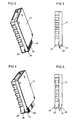
- FIGS 2 and 3 show an uncoded plug-in module in perspective view or side view.
- Your housing 21 extends essentially across the width of a slot grid, that is 10.16 mm.
- a populated circuit board 22 housed the housing 21 on the side with which it is in insertion slots of the carrier unit is used, protrudes laterally.
- For insertion in the carrier unit shown in Figure 1 become the assemblies with pivot pins 23 and 24 on the upper edge of the carrier unit hooked in and pivoted down so that the side edges the printed circuit board 22 with contact surfaces located on its upper side a connector with contact springs in the Make insertion slots.
- the housing 27 of a coded assembly has one for coding Extension 28 on one side and one to a corresponding one Extension of an adjacent coded plug-in module corresponding recess 29 on the other side, so that coded assemblies also side by side in any the slots 11 ... 18 can be inserted.
- the coding is designed as a change in the width of pivot pins 30 and 31, so that an uncoded module is already inserted immediately on the right side of a coded assembly in the swivel is prevented. This will be on the coding pin acting forces are kept low and a Damage to the carrier unit as well as the plug-in modules practically excluded by the coding.
- a coded module can thus on the right just another coded one, on the left side, however, either an uncoded or an coded plug-in module can be used.
- a facility for connecting external lines is thus by the Coding reliably ensures that the required Minimum creepage distance for 230 V modules is observed.
- the invention is based on a Device for connecting external lines as a carrier unit and conversion modules as electronic modules for the slots the carrier unit has been described is the invention also with any other carrier units for coding Plug-in modules suitable. For example, it can be used for coding of plug-in modules in a rack or of Front plugs on one equipped with input or output modules programmable logic controller can be used.
Landscapes
- Engineering & Computer Science (AREA)
- Microelectronics & Electronic Packaging (AREA)
- Details Of Connecting Devices For Male And Female Coupling (AREA)
- Connector Housings Or Holding Contact Members (AREA)
- Coupling Device And Connection With Printed Circuit (AREA)
- Transmission Systems Not Characterized By The Medium Used For Transmission (AREA)
- Quick-Acting Or Multi-Walled Pipe Joints (AREA)
Description
- Figur 1
- eine Trägereinheit einer Einrichtung zum Anschluß externer Leitungen,
- Figur 2
- eine Perspektivansicht einer uncodierten Steckbaugruppe,
- Figur 3
- eine Seitenansicht der uncodierten Steckbaugruppe nach Figur 2,
- Figur 4
- eine Perspektivansicht einer codierten Steckbaugruppe und
- Figur 5
- eine Seitenansicht der codierten Steckbaugruppe nach Figur 4.
Claims (3)
- Einrichtung zur Codierung von Steckbaugruppen, die für eine Bestückung in einer Trägereinheit mit äquidistant nebeneinander angeordneten Steckplätzen vorgesehen sind,
dadurch gekennzeichnet,daß codierte Steckbaugruppen einen Fortsatz (28) auf der einen Seite und eine zu einem entsprechenden Fortsatz einer benachbarten codierten Steckbaugruppe korrespondierende Ausnehmung (29) auf der anderen Seite aufweisen, so daß sie beliebig nebeneinander in die Steckplätze (11 ... 18) einsteckbar sind, unddaß uncodierte Steckbaugruppen keine derartige Ausnehmung aufweisen, so daß sie auf der einen Seite einer codierten Steckbaugruppe nicht in einen unmittelbar danebenliegenden Steckplatz einsteckbar sind. - Einrichtung nach Anspruch 1, dadurch gekennzeichnet,daß die Baugruppen zum Einstecken an den Steckplätzen (11 ... 18) um ein Drehgelenk schwenkbar sind unddaß sich Fortsatz (28) und Ausnehmung (29) codierter Steckbaugruppen im Bereich des Drehgelenks befinden, so daß durch einen Fortsatz gegebenenfalls bereits das Einsetzen einer uncodierten Steckbaugruppe in das Drehgelenk verhindert wird.
- Einrichtung zum Anschluß externer Leitungen mit äquidistant nebeneinander angeordneten Steckplätzen (11 ... 18) und mit Steckbaugruppen, die eine Signalanpassungsschaltung für auf den externen Leitungen geführte Signale enthalten,
dadurch gekennzeichnet,daß je Steckplatz zwei Signalkanäle vorgesehen sind, deren Anschlußelemente (1 ... 10) in Zählrichtung der Steckplätze im halben Steckplatzraster nebeneinander angeordnet sind, wobei der Abstand der Anschlußelemente benachbarter Kanäle größer ist als die geforderte Mindestkriechstrecke für Ströme bei einer niedrigen von mehreren möglichen Betriebsspannungen und kleiner als die geforderte Mindestkriechstrecke bei einer höheren der möglichen Betriebsspannungen und wobei der Abstand der Anschlußelemente zweier Kanäle, zwischen denen Anschlußelemente eines anderen Kanals liegen, größer ist als die geforderte Mindestkriechstrecke für Ströme bei der höheren Betriebsspannung,daß codierte Steckbaugruppen mit einer höheren Betriebsspannung eine Signalanpassungsschaltung für einen Kanal enthalten, dessen Anschlußelemente auf der einen Seite liegen und einen Fortsatz (28) auf der einen Seite und eine zu einem entsprechenden Fortsatz einer benachbarten codierten Steckbaugruppe korrespondierende Ausnehmung (29) auf der anderen Seite aufweisen, so daß sie beliebig nebeneinander in die Steckplätze einsteckbar sind, unddaß uncodierte Steckbaugruppen mit einer niedrigen Betriebsspannung eine Signalanpassungsschaltung für beide Signalkanäle enthalten und keine derartige Ausnehmung (29) aufweisen, so daß sie auf der einen Seite einer codierten Steckbaugruppe nicht in einen unmittelbar danebenliegenden Steckplatz einsteckbar sind.
Applications Claiming Priority (3)
| Application Number | Priority Date | Filing Date | Title |
|---|---|---|---|
| DE29620407U DE29620407U1 (de) | 1996-11-22 | 1996-11-22 | Einrichtung zur Codierung von Steckbaugruppen sowie Einrichtung zum Anschluß externer Leitungen mit einer derartigen Codiereinrichtung |
| DE29620407U | 1996-11-22 | ||
| PCT/DE1997/002726 WO1998024282A2 (de) | 1996-11-22 | 1997-11-20 | Einrichtung zur codierung von steckbaugruppen sowie einrichtung zum anschluss externer leitungen mit einer derartigen codiereinrichtung |
Publications (2)
| Publication Number | Publication Date |
|---|---|
| EP0940066A2 EP0940066A2 (de) | 1999-09-08 |
| EP0940066B1 true EP0940066B1 (de) | 2000-10-11 |
Family
ID=8032369
Family Applications (1)
| Application Number | Title | Priority Date | Filing Date |
|---|---|---|---|
| EP97951793A Expired - Lifetime EP0940066B1 (de) | 1996-11-22 | 1997-11-20 | Einrichtung zur codierung von steckbaugruppen sowie einrichtung zum anschluss externer leitungen mit einer derartigen codiereinrichtung |
Country Status (10)
| Country | Link |
|---|---|
| US (1) | US6196878B1 (de) |
| EP (1) | EP0940066B1 (de) |
| JP (1) | JP2001504641A (de) |
| KR (1) | KR20000057163A (de) |
| CN (1) | CN1112745C (de) |
| AT (1) | ATE196967T1 (de) |
| DE (2) | DE29620407U1 (de) |
| ES (1) | ES2151749T3 (de) |
| ID (1) | ID21752A (de) |
| WO (1) | WO1998024282A2 (de) |
Families Citing this family (2)
| Publication number | Priority date | Publication date | Assignee | Title |
|---|---|---|---|---|
| DE20011382U1 (de) * | 2000-06-29 | 2001-11-08 | Siemens Building Technologies AG, Zürich | Verbindungsmodul |
| FR3103076B1 (fr) * | 2019-11-07 | 2022-02-25 | Alstom Transp Tech | Ensemble amélioré constitué d’un support de réception de cartes électroniques et d’un châssis électronique en mezzanine |
Citations (5)
| Publication number | Priority date | Publication date | Assignee | Title |
|---|---|---|---|---|
| CH607542A5 (en) * | 1976-12-16 | 1978-12-29 | Siemens Ag Albis | Printed circuit board mechanical coding system |
| US4401358A (en) * | 1980-01-14 | 1983-08-30 | Olympus Optical Co. Ltd. | Device for preventing erroneous insertion of a plurality of print substrates into corresponding connectors in a rack |
| EP0113795A2 (de) * | 1982-12-21 | 1984-07-25 | Siemens Aktiengesellschaft | Baugruppenträger für einseitig bestückte Flachbaugruppen in Planaranordnung |
| EP0392629A1 (de) * | 1989-04-14 | 1990-10-17 | Connector Systems Technology N.V. | Verbindersatz mit Mitteln zur Codierung |
| DE4323440A1 (de) * | 1993-05-14 | 1995-02-02 | Siemens Ag | Elektronisches Gerät, insbesondere Automatisierungsgerät |
Family Cites Families (13)
| Publication number | Priority date | Publication date | Assignee | Title |
|---|---|---|---|---|
| DE271606C (de) | ||||
| SE311123B (de) * | 1968-02-15 | 1969-05-27 | Iwema Ab | |
| US3668605A (en) * | 1970-08-10 | 1972-06-06 | North Electric Co | Multi-point program plug and receptacle connector arrangement having positive alignment prior to positive mating |
| DE2511135A1 (de) * | 1975-03-14 | 1976-09-23 | Licentia Gmbh | Codierelement fuer schaltungsplatten |
| US4283796A (en) * | 1980-04-28 | 1981-08-11 | Motorola, Inc. | Portable device with housing for battery and plug-in module |
| AR242469A1 (es) * | 1984-09-27 | 1993-03-31 | Siemens Ag | Disposicion de conexion electrica multipolar a enchufe con una disposicion de codificacion. |
| DE3603750C3 (de) * | 1986-02-06 | 1996-10-17 | Siemens Ag | Automatisierungsgerät |
| US4790763A (en) * | 1986-04-22 | 1988-12-13 | Amp Incorporated | Programmable modular connector assembly |
| DD271606A1 (de) * | 1987-02-12 | 1989-09-06 | Berlin Treptow Veb K | Vorrichtung zum loesbaren befestigen elektronischer kompaktbaugruppen am montagerahmen |
| FR2625603B1 (fr) * | 1987-12-30 | 1993-05-07 | Telemecanique Electrique | Appareil interrupteur electrique protege et son dispositif de fixation |
| US5253140A (en) * | 1988-03-12 | 1993-10-12 | Fanuc Ltd. | Connector unit for input/output module of programmable controller having disengagement lever |
| DE4402002B4 (de) * | 1994-01-18 | 2005-10-27 | Wago Verwaltungsgesellschaft Mbh | E/A-Module/ für einen Datenbus |
| US5737194A (en) * | 1996-07-29 | 1998-04-07 | Cray Research, Inc. | Input/output module assembly |
-
1996
- 1996-11-22 DE DE29620407U patent/DE29620407U1/de not_active Expired - Lifetime
-
1997
- 1997-11-20 ES ES97951793T patent/ES2151749T3/es not_active Expired - Lifetime
- 1997-11-20 KR KR1019990704452A patent/KR20000057163A/ko not_active Withdrawn
- 1997-11-20 US US09/308,766 patent/US6196878B1/en not_active Expired - Fee Related
- 1997-11-20 CN CN97199617A patent/CN1112745C/zh not_active Expired - Fee Related
- 1997-11-20 ID IDW990401A patent/ID21752A/id unknown
- 1997-11-20 EP EP97951793A patent/EP0940066B1/de not_active Expired - Lifetime
- 1997-11-20 DE DE59702472T patent/DE59702472D1/de not_active Expired - Fee Related
- 1997-11-20 WO PCT/DE1997/002726 patent/WO1998024282A2/de not_active Ceased
- 1997-11-20 JP JP52413898A patent/JP2001504641A/ja active Pending
- 1997-11-20 AT AT97951793T patent/ATE196967T1/de not_active IP Right Cessation
Patent Citations (5)
| Publication number | Priority date | Publication date | Assignee | Title |
|---|---|---|---|---|
| CH607542A5 (en) * | 1976-12-16 | 1978-12-29 | Siemens Ag Albis | Printed circuit board mechanical coding system |
| US4401358A (en) * | 1980-01-14 | 1983-08-30 | Olympus Optical Co. Ltd. | Device for preventing erroneous insertion of a plurality of print substrates into corresponding connectors in a rack |
| EP0113795A2 (de) * | 1982-12-21 | 1984-07-25 | Siemens Aktiengesellschaft | Baugruppenträger für einseitig bestückte Flachbaugruppen in Planaranordnung |
| EP0392629A1 (de) * | 1989-04-14 | 1990-10-17 | Connector Systems Technology N.V. | Verbindersatz mit Mitteln zur Codierung |
| DE4323440A1 (de) * | 1993-05-14 | 1995-02-02 | Siemens Ag | Elektronisches Gerät, insbesondere Automatisierungsgerät |
Also Published As
| Publication number | Publication date |
|---|---|
| CN1237324A (zh) | 1999-12-01 |
| JP2001504641A (ja) | 2001-04-03 |
| WO1998024282A3 (de) | 1998-11-05 |
| ATE196967T1 (de) | 2000-10-15 |
| CN1112745C (zh) | 2003-06-25 |
| US6196878B1 (en) | 2001-03-06 |
| DE29620407U1 (de) | 1998-01-02 |
| KR20000057163A (ko) | 2000-09-15 |
| DE59702472D1 (de) | 2000-11-16 |
| ES2151749T3 (es) | 2001-01-01 |
| ID21752A (id) | 1999-07-22 |
| EP0940066A2 (de) | 1999-09-08 |
| WO1998024282A2 (de) | 1998-06-04 |
Similar Documents
| Publication | Publication Date | Title |
|---|---|---|
| EP0712267B1 (de) | Modulare Steuerungsanlage mit integriertem Feldbusanschluss | |
| EP0895708B1 (de) | Modulares, baugruppenweise erweiterbares peripheriegerät mit selbstaufbauender elektrischer verbindung | |
| EP1353412B1 (de) | Modularer Steckverbinder | |
| DE19535277C1 (de) | Baugruppe eines Automatisierungsgeräts | |
| EP1174781B1 (de) | Einrichtung zur Signalübertragung | |
| EP0452658B1 (de) | Anschlusseinrichtung für die Hausleittechnik | |
| DE19615093C2 (de) | Automatisierungsgerät | |
| WO1999054632A1 (de) | Modulares elektrofluidisches baukastensystem | |
| EP0546455A2 (de) | Elektronische Steuereinrichtung zum Schalten mehrerer elektrischer Lasten | |
| DE3740290C2 (de) | Vorrichtung zum Steuern und/oder Regeln von Prozessen | |
| EP3491472A1 (de) | Reihenmodul, verbindungsmodul und modular ausgebildete steuerungsanordnung | |
| DE102013011377A1 (de) | Modulare Feldgeräteanschlusseinheit | |
| EP0740082A1 (de) | Modularer elektrischer Teil für einen Ventilblock | |
| EP0895707A1 (de) | Modulares, baugruppenweise erweiterbares peripheriegerät mit selbsttragendem aufbau | |
| EP0940066B1 (de) | Einrichtung zur codierung von steckbaugruppen sowie einrichtung zum anschluss externer leitungen mit einer derartigen codiereinrichtung | |
| DE3910913A1 (de) | Pneumatische oder hydraulische ventileinheit | |
| DE19736581A1 (de) | Feldbusanordnung | |
| WO1998024153A1 (de) | Einrichtung zur codierung von steckplätzen | |
| DE10019860C1 (de) | Verfahren und Einrichtung zum Prüfen von Kabelbäumen | |
| DE10052846C2 (de) | Anordnung zur Verzweigung elektrischer Stromkreise im explosionsgefährdeten Bereich | |
| DE4013815C2 (de) | Steuerschaltung für Maschinen | |
| WO2001079871A1 (de) | Verfahren und einrichtung zum prüfen von kabelbäumen | |
| EP1085691A2 (de) | System zur prozessorgesteuerten Übertragung von elektrischen Signalen und elektrischer Energie innerhalb eines militärischen Fahrzeugs | |
| EP0585548A1 (de) | Feldstation für ein von einem Steuercomputer gesteuertes serielles Bussystem | |
| DE29810091U1 (de) | Ventilterminal mit einer Reihe von Schaltventilen |
Legal Events
| Date | Code | Title | Description |
|---|---|---|---|
| PUAI | Public reference made under article 153(3) epc to a published international application that has entered the european phase |
Free format text: ORIGINAL CODE: 0009012 |
|
| 17P | Request for examination filed |
Effective date: 19990520 |
|
| AK | Designated contracting states |
Kind code of ref document: A2 Designated state(s): AT CH DE ES FR GB LI |
|
| GRAG | Despatch of communication of intention to grant |
Free format text: ORIGINAL CODE: EPIDOS AGRA |
|
| GRAG | Despatch of communication of intention to grant |
Free format text: ORIGINAL CODE: EPIDOS AGRA |
|
| GRAH | Despatch of communication of intention to grant a patent |
Free format text: ORIGINAL CODE: EPIDOS IGRA |
|
| 17Q | First examination report despatched |
Effective date: 20000217 |
|
| GRAH | Despatch of communication of intention to grant a patent |
Free format text: ORIGINAL CODE: EPIDOS IGRA |
|
| GRAA | (expected) grant |
Free format text: ORIGINAL CODE: 0009210 |
|
| AK | Designated contracting states |
Kind code of ref document: B1 Designated state(s): AT CH DE ES FR GB LI |
|
| REF | Corresponds to: |
Ref document number: 196967 Country of ref document: AT Date of ref document: 20001015 Kind code of ref document: T |
|
| REG | Reference to a national code |
Ref country code: CH Ref legal event code: EP |
|
| REG | Reference to a national code |
Ref country code: CH Ref legal event code: NV Representative=s name: SIEMENS SCHWEIZ AG |
|
| REF | Corresponds to: |
Ref document number: 59702472 Country of ref document: DE Date of ref document: 20001116 |
|
| REG | Reference to a national code |
Ref country code: ES Ref legal event code: FG2A Ref document number: 2151749 Country of ref document: ES Kind code of ref document: T3 |
|
| GBT | Gb: translation of ep patent filed (gb section 77(6)(a)/1977) |
Effective date: 20001213 |
|
| ET | Fr: translation filed | ||
| PLBE | No opposition filed within time limit |
Free format text: ORIGINAL CODE: 0009261 |
|
| STAA | Information on the status of an ep patent application or granted ep patent |
Free format text: STATUS: NO OPPOSITION FILED WITHIN TIME LIMIT |
|
| 26N | No opposition filed | ||
| REG | Reference to a national code |
Ref country code: GB Ref legal event code: IF02 |
|
| PGFP | Annual fee paid to national office [announced via postgrant information from national office to epo] |
Ref country code: ES Payment date: 20081216 Year of fee payment: 12 Ref country code: AT Payment date: 20081017 Year of fee payment: 12 |
|
| REG | Reference to a national code |
Ref country code: CH Ref legal event code: PCAR Free format text: SIEMENS SCHWEIZ AG;INTELLECTUAL PROPERTY FREILAGERSTRASSE 40;8047 ZUERICH (CH) |
|
| PGFP | Annual fee paid to national office [announced via postgrant information from national office to epo] |
Ref country code: FR Payment date: 20081118 Year of fee payment: 12 |
|
| PGFP | Annual fee paid to national office [announced via postgrant information from national office to epo] |
Ref country code: DE Payment date: 20090119 Year of fee payment: 12 |
|
| PGFP | Annual fee paid to national office [announced via postgrant information from national office to epo] |
Ref country code: GB Payment date: 20081110 Year of fee payment: 12 Ref country code: CH Payment date: 20090205 Year of fee payment: 12 |
|
| REG | Reference to a national code |
Ref country code: CH Ref legal event code: PL |
|
| GBPC | Gb: european patent ceased through non-payment of renewal fee |
Effective date: 20091120 |
|
| REG | Reference to a national code |
Ref country code: FR Ref legal event code: ST Effective date: 20100730 |
|
| PG25 | Lapsed in a contracting state [announced via postgrant information from national office to epo] |
Ref country code: AT Free format text: LAPSE BECAUSE OF NON-PAYMENT OF DUE FEES Effective date: 20091120 |
|
| PG25 | Lapsed in a contracting state [announced via postgrant information from national office to epo] |
Ref country code: LI Free format text: LAPSE BECAUSE OF NON-PAYMENT OF DUE FEES Effective date: 20091130 Ref country code: FR Free format text: LAPSE BECAUSE OF NON-PAYMENT OF DUE FEES Effective date: 20091130 Ref country code: CH Free format text: LAPSE BECAUSE OF NON-PAYMENT OF DUE FEES Effective date: 20091130 |
|
| PG25 | Lapsed in a contracting state [announced via postgrant information from national office to epo] |
Ref country code: DE Free format text: LAPSE BECAUSE OF NON-PAYMENT OF DUE FEES Effective date: 20100601 |
|
| PG25 | Lapsed in a contracting state [announced via postgrant information from national office to epo] |
Ref country code: GB Free format text: LAPSE BECAUSE OF NON-PAYMENT OF DUE FEES Effective date: 20091120 |
|
| REG | Reference to a national code |
Ref country code: ES Ref legal event code: FD2A Effective date: 20110408 |
|
| PG25 | Lapsed in a contracting state [announced via postgrant information from national office to epo] |
Ref country code: ES Free format text: LAPSE BECAUSE OF NON-PAYMENT OF DUE FEES Effective date: 20110328 |
|
| PG25 | Lapsed in a contracting state [announced via postgrant information from national office to epo] |
Ref country code: ES Free format text: LAPSE BECAUSE OF NON-PAYMENT OF DUE FEES Effective date: 20091121 |