EP0939263A1 - Pipe flange sealing ring - Google Patents
Pipe flange sealing ring Download PDFInfo
- Publication number
- EP0939263A1 EP0939263A1 EP99400060A EP99400060A EP0939263A1 EP 0939263 A1 EP0939263 A1 EP 0939263A1 EP 99400060 A EP99400060 A EP 99400060A EP 99400060 A EP99400060 A EP 99400060A EP 0939263 A1 EP0939263 A1 EP 0939263A1
- Authority
- EP
- European Patent Office
- Prior art keywords
- seal
- flanges
- joint
- flange
- rigid
- Prior art date
- Legal status (The legal status is an assumption and is not a legal conclusion. Google has not performed a legal analysis and makes no representation as to the accuracy of the status listed.)
- Granted
Links
Images
Classifications
-
- F—MECHANICAL ENGINEERING; LIGHTING; HEATING; WEAPONS; BLASTING
- F16—ENGINEERING ELEMENTS AND UNITS; GENERAL MEASURES FOR PRODUCING AND MAINTAINING EFFECTIVE FUNCTIONING OF MACHINES OR INSTALLATIONS; THERMAL INSULATION IN GENERAL
- F16L—PIPES; JOINTS OR FITTINGS FOR PIPES; SUPPORTS FOR PIPES, CABLES OR PROTECTIVE TUBING; MEANS FOR THERMAL INSULATION IN GENERAL
- F16L23/00—Flanged joints
- F16L23/16—Flanged joints characterised by the sealing means
- F16L23/18—Flanged joints characterised by the sealing means the sealing means being rings
-
- Y—GENERAL TAGGING OF NEW TECHNOLOGICAL DEVELOPMENTS; GENERAL TAGGING OF CROSS-SECTIONAL TECHNOLOGIES SPANNING OVER SEVERAL SECTIONS OF THE IPC; TECHNICAL SUBJECTS COVERED BY FORMER USPC CROSS-REFERENCE ART COLLECTIONS [XRACs] AND DIGESTS
- Y10—TECHNICAL SUBJECTS COVERED BY FORMER USPC
- Y10S—TECHNICAL SUBJECTS COVERED BY FORMER USPC CROSS-REFERENCE ART COLLECTIONS [XRACs] AND DIGESTS
- Y10S277/00—Seal for a joint or juncture
- Y10S277/917—Seal including frangible feature
Definitions
- the present invention relates to improvements made to the seals intended to be clamped between two connection flanges piping and the invention relates more particularly to such seals which have a sealing ring including a rigid metallic annular part of which are joined together several radiating metal legs can be bent along the outline of a flange support.
- pipes can be made up of pipe sections connected end-to-end using flanges between which seals are arranged.
- seals in particular have dimensional characteristics (inner diameter in particular) which are in correspondence with the diameter of the flanges, which their turn are in correspondence with the diameter of the pipe and the permissible nominal pressure. These dimensions can be normalized.
- seals can only be used within the limits of a nominal pressure for which they have been designed.
- the seals currently used have other drawbacks, including: the impossibility of controlling the characteristics of a gasket in place between tight flanges; Possibility of re-use a gasket already used and having already been compressed ; inability to check the correct centering of the joint as soon as the two flanges are presented one opposite the other on either side of the joint.
- the object of the invention is therefore essentially to propose a simple technical solution that gives better satisfaction of the various requirements of the practice and which eliminates, or at least reduces the various disadvantages above, by proposing an original joint structure seal for flanged industrial piping which can be used for a whole range of flanges of various diameters so as to reduce stocks of materials in reserve both at the manufacturer and at the user, which leads to easy positioning and controllable centering even on vertical flanges, which authorizes a check of its characteristics after assembly between the flanges, which cannot be reused after disassembly, and which ultimately retains the features sealing and mechanical of the front seals and does not present a significant additional manufacturing cost.
- a seal as mentioned is characterized in the preamble, being arranged in accordance with the invention, in that, the seal must be able be mounted between flanges of various dimensions transverse, the metal tabs have a length exceeding the corresponding transverse dimension larger flanges on which the joint can be mounted, which allows the legs to be folded in match the exact size of a mounting flange so that the joint can be supported properly centered by said flange prior to assembly and mutual tightening of the two flanges.
- a seal according to the invention can be fitted indifferently on a plurality of flanges of dimensions various (flanges belonging to a range of range given dimensional; flanges corresponding to different standards; etc.)
- the legs include marks corresponding to predetermined dimensions of flanges to facilitate their folding to the exact dimension for correct centering of the seal on the flanges during of its implementation.
- the legs radiant are four in number, two to two substantially diametrically opposite and mutually offset angularly around 90 °.
- At least one leg radiant has indications, including alphanumeric and / or colored, to identify the class of attached, these indications being affixed on the end of the protruding tab which remains visible outside the flanges assemblies.
- Such an arrangement of radiating legs which advantageously are added by welding on the part metallic ring seal, offers the advantage considerable to leave intact the part forming joint sealing itself: it can therefore continue to be constituted as an anterior joint of the same type and continues to have the same characteristics functional.
- the provisions specific to the invention can be applied to joints of various types, i.e. seals in which the above annular part rigid constitutes a rigid core of the joint, or alternatively seals in which the rigid annular part is a rigid ring externally surrounding the seal and having a thickness less than this: the seals arranged in accordance with the invention can therefore retain the anti-crushing device.
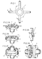
- FIG 1 is shown schematically an annular seal J intended to be clamped between two pipe connection flanges industrial, for example in the chemical industry or oil.
- This joint J comprises a sealing ring 1 including a rigid metallic annular part (not shown in fig. 1) of which various examples will be given further.
- metallic radiating legs 2 are integral with the aforementioned rigid annular part (being especially welded to it, but can also be in one piece with it) and each have a length appreciably exceeding the transverse dimension of the largest of a set of flanges intended to be equipped with said seal.
- legs can be in any number, but the solution that seems most effective both on the technically and economically is to plan four legs, two by two substantially diametrically opposite and mutually offset angularly by about 90 °.
- Each tab 2 can advantageously include marks 3, engraved or painted, which are arranged in correspondence with diameters (in principle standardized) flanges. Possibly some of these benchmarks, or other benchmarks independent of these, can be planned, or even premarked to constitute a line mechanical weakening, with a view to cutting the leg if it is too long and is likely to constitute a gene after mounting on the flange.
- legs can be painted, in any or part, in a codified way depending for example on diameter of the seal and / or nominal pressure and / or any other information (date of installation for example).
- each leg in one predetermined location thereof (for example end 4 painted differently), to provide a different coded information, for example on the seal class, the nominal pressure of the seal, its structure, its date of pose ...
- the legs 2 are folded against the periphery of the flange 5, without moving the seal J in relation to the flange (fig. 2B).
- the extremities folded down 6 then appear on the periphery of the flange 5.
- the protrusion of the ends 6 of the legs 2 allows a visual check, after tightening and possibly in during use, maintaining the J-joint in position centered.
- the color codings and / or inscriptions appearing on the ends 6 of the legs 2 allow immediate and rapid control of characteristics of the seal, its age, ...
- a joint arranged according to the invention is no longer linked to a dimension precise flange, but can be mounted on flanges various dimensions within a dimensional range predetermined, the sealing ring 1 then being designed to withstand the highest corresponding pressure planned for the range of flanges and pipes corresponding.
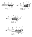
- a joint J 1 must "corrugated joint" comprising a sealing ring 1 including a corrugated metallic annular core 11 coated on either side by two graphite coatings 12. The tabs 12 are then joined by welding on the edge of the metallic core 12 appearing on the outer edge of the sealing ring 1.
- FIG. 5 is shown in the same way a seal J 2 called "striated seal” comprising a sealing ring 1 including a metallic annular core 13 whose opposite main faces 14 are striated and coated with respective graphite layers 15.
- the sealing ring 1 is further provided with a metallic external ring 16 (for example an anti-crushing ring of calibrated thickness less than that of the sealing ring) on which the legs 2.
- the legs 2 are attached directly to the outer edge of the metal core 13 as illustrated in FIG. 6 for the joint J 3 (which is shown equipped, for example, with an inner metal centering ring 17).
- the invention finds a particularly advantageous application in the coated metalloplastic seals J 4 illustrated in FIG. 7, which comprises a sealing ring 1 consisting of an annular metal casing 18, for example made of stainless steel which surrounds an inner lining 19 forming core, for example made of expanded graphite and which supports on its two opposite annular faces respective layers of non-stick coating 20, for example made of graphite or a synthetic material such as polytetrafluoroethylene.
- An external anti-crushing ring 16 and / or an internal ring can be secured to the casing 18.
- the legs 2 are secured either directly to the casing 18 if no anti-crushing ring is provided, or to the ring external 16 if it exists.
Applications Claiming Priority (2)
| Application Number | Priority Date | Filing Date | Title |
|---|---|---|---|
| FR9802341 | 1998-02-26 | ||
| FR9802341A FR2775328B1 (fr) | 1998-02-26 | 1998-02-26 | Joint d'etancheite pour bride de tuyauterie |
Publications (2)
| Publication Number | Publication Date |
|---|---|
| EP0939263A1 true EP0939263A1 (de) | 1999-09-01 |
| EP0939263B1 EP0939263B1 (de) | 2004-04-21 |
Family
ID=9523401
Family Applications (1)
| Application Number | Title | Priority Date | Filing Date |
|---|---|---|---|
| EP99400060A Expired - Lifetime EP0939263B1 (de) | 1998-02-26 | 1999-01-12 | Pipe flange sealing ring |
Country Status (5)
| Country | Link |
|---|---|
| US (1) | US6367803B1 (de) |
| EP (1) | EP0939263B1 (de) |
| AT (1) | ATE265015T1 (de) |
| DE (1) | DE69916518T2 (de) |
| FR (1) | FR2775328B1 (de) |
Cited By (4)
| Publication number | Priority date | Publication date | Assignee | Title |
|---|---|---|---|---|
| EP1136734A1 (de) * | 2000-03-22 | 2001-09-26 | Kroll & Ziller GmbH & Co. KG | Dichtung, insbesondere Flanschdichtung |
| WO2007082887A1 (de) * | 2006-01-17 | 2007-07-26 | Alfred Jung | Dichtungsanordnung |
| CN103438304A (zh) * | 2013-08-15 | 2013-12-11 | 天津钢铁集团有限公司 | 法兰垫片及确定法兰垫片和法兰孔同心的方法 |
| EP3290754A1 (de) * | 2016-08-30 | 2018-03-07 | Frenzelit Werke GmbH | Weichstoffdichtung mit randeinfassung |
Families Citing this family (45)
| Publication number | Priority date | Publication date | Assignee | Title |
|---|---|---|---|---|
| US6260853B1 (en) * | 1998-06-23 | 2001-07-17 | Kc Multi-Ring Products, Inc. | Gasket having centering features |
| JP2002106315A (ja) * | 2000-09-29 | 2002-04-10 | Honda Motor Co Ltd | オイルシールを有する機械 |
| US6845984B2 (en) * | 2000-11-27 | 2005-01-25 | Michael Doyle | Keeper for positioning ring seals |
| US7247220B2 (en) * | 2001-11-09 | 2007-07-24 | Foster Wheeler Usa Corporation | Coke drum discharge system |
| US20030127314A1 (en) * | 2002-01-10 | 2003-07-10 | Bell Robert V. | Safe and automatic method for removal of coke from a coke vessel |
| US20030209863A1 (en) * | 2002-03-21 | 2003-11-13 | Kyle Gregoire | Self-aligning sealing apparatus providing axial sealing and controlled compression limits |
| BR0211785B1 (pt) * | 2002-05-30 | 2011-01-11 | acoplamento para tubulação. | |
| BR0202511A (pt) * | 2002-07-03 | 2004-05-11 | Manegro Administracao E Partic | Junta de vedação de flanges de tubulações e equipamentos, processo de fabricação da junta de vedação, e anel de vedação para junta de vedação |
| US6845983B1 (en) * | 2002-09-13 | 2005-01-25 | Acadia Elastomers Corporation | Gasket with outer edge damping channel and method and apparatus for manufacturing same |
| DE10252141A1 (de) * | 2002-11-09 | 2004-07-01 | Prominent Dosiertechnik Gmbh | Flachdichtungsring |
| US7364166B2 (en) * | 2003-01-24 | 2008-04-29 | Applied Engineered Surfaces, Inc. | Seal and retainer for a fluid connection |
| US6857638B2 (en) * | 2003-02-14 | 2005-02-22 | Rubber Fab, Inc. | Gasket for sanitary fittings |
| US7100925B2 (en) * | 2003-07-31 | 2006-09-05 | Perkin Elmer, Inc. | Pressure energized metallic seal |
| US20050078390A1 (en) * | 2003-08-22 | 2005-04-14 | Jacques Gourde | Gasket for a sector of a disc filter |
| WO2005057056A2 (en) * | 2003-12-05 | 2005-06-23 | Garlock Sealing Technologies, Llc | Gasket of non-rounded shape with installation aids |
| US20050275222A1 (en) * | 2004-06-14 | 2005-12-15 | Yoakam John A | Gasket for a fluid connection |
| US7621568B2 (en) | 2006-04-25 | 2009-11-24 | Visteon Global Technologies, Inc. | Block fitting and seal structure |
| JP4324607B2 (ja) * | 2006-08-11 | 2009-09-02 | 日本ピラー工業株式会社 | 非石綿ガスケット |
| DE102006056819A1 (de) * | 2006-12-01 | 2008-06-05 | Deutz Ag | Erhöhung der übertragbaren Reibkräfte an Dichtstellen |
| DE202007003483U1 (de) * | 2007-03-08 | 2008-04-17 | Boa Balg- Und Kompensatoren-Technologie Gmbh | Leitungsverbindung einer Einrichtung zur Abgasrückführung |
| KR100907990B1 (ko) * | 2007-10-04 | 2009-07-16 | 지엠대우오토앤테크놀로지주식회사 | 장착 확인이 가능한 가스켓 |
| RU2371620C1 (ru) * | 2008-03-07 | 2009-10-27 | Общество с ограниченной ответственностью "ИЛЬМА" | Уплотнительная прокладка для герметизации фланцевого соединения |
| US9447882B2 (en) * | 2008-04-17 | 2016-09-20 | Parker-Hannifin Corporation | Compression-limited gasket construction |
| GB2462810B (en) * | 2008-08-18 | 2010-07-21 | Rolls Royce Plc | Sealing means |
| US20100230962A1 (en) * | 2008-12-08 | 2010-09-16 | Flowsmart, Inc. | Self-aligning flanged joint and alignment rim therefor |
| SG172260A1 (en) * | 2008-12-19 | 2011-07-28 | Mtc Brattberg Ab | Layer for use in combination with an insert half, and insert half |
| EP2226544B1 (de) | 2009-03-07 | 2012-06-13 | Kempchen Dichtungstechnik GmbH | Kammprofildichtring |
| GB0922625D0 (en) | 2009-12-24 | 2010-02-10 | Flexitallic Ltd | A gasket |
| US9388924B2 (en) | 2011-03-18 | 2016-07-12 | Advanced Sealing, Inc. | Alky-one gasket |
| US20120235365A1 (en) * | 2011-03-18 | 2012-09-20 | Alan Stubblefield | Alky-one gasket |
| US9701388B2 (en) * | 2011-05-11 | 2017-07-11 | Aviation Devices & Electronic Components, Llc | Gasket having a pliable resilient body with a perimeter having characteristics different than the body |
| EP2831482B1 (de) * | 2012-03-26 | 2019-10-09 | Lamons Gasket Company | Flanschdichtung |
| WO2013181390A1 (en) * | 2012-05-30 | 2013-12-05 | The Reliable Automatic Sprinkler Co., Inc. | Visual assembly aid for fire sprinkler and method for use |
| DE202013003026U1 (de) * | 2013-04-02 | 2014-08-14 | Alfred Jung | Geprägte gestanzte Flachdichtung für Flanschverbindungen mit Sollbruchnut |
| DE102013006777A1 (de) * | 2013-04-18 | 2014-10-23 | Samson Aktiengesellschaft | Stellgerät für eine verfahrenstechnische Anlage |
| US9512934B2 (en) * | 2013-06-18 | 2016-12-06 | Fisher Controls International Llc | Seal assemblies for use with fluid valves |
| DE102013214118A1 (de) | 2013-07-18 | 2015-01-22 | Siemens Aktiengesellschaft | Flanschsystem sowie Montageverfahren für ein Flanschsystem |
| CA2953900C (en) * | 2014-07-01 | 2021-09-07 | Lamons Gasket Company | Electrically isolating, fire-safe sealing element |
| GB201514584D0 (en) * | 2015-08-17 | 2015-09-30 | Flexitallic Ltd And Flexitallic Invest Inc | A gasket |
| WO2017042590A1 (en) * | 2015-09-10 | 2017-03-16 | Lamons Uk Limited | Sealing device for flanges |
| CN106764158A (zh) * | 2017-01-22 | 2017-05-31 | 江苏顺通管业有限公司 | 一种带颈平焊法兰 |
| US11371868B2 (en) * | 2017-08-31 | 2022-06-28 | Micro Motion, Inc. | Conductive polymer reference connection for magnetic flowmeter |
| US11309177B2 (en) | 2018-11-06 | 2022-04-19 | Stmicroelectronics S.R.L. | Apparatus and method for manufacturing a wafer |
| WO2020119259A1 (zh) * | 2018-12-10 | 2020-06-18 | 清华大学 | 一种平板结构密封圈及密封结构 |
| IT201900015416A1 (it) | 2019-09-03 | 2021-03-03 | St Microelectronics Srl | Apparecchio per la crescita di una fetta di materiale semiconduttore, in particolare di carburo di silicio, e procedimento di fabbricazione associato |
Citations (5)
| Publication number | Priority date | Publication date | Assignee | Title |
|---|---|---|---|---|
| DE1755658U (de) * | 1954-11-30 | 1957-11-07 | Siemens Ag | Anordnung zur zentrierung bzw. befestigung von dichtungsringen. |
| DE2105381A1 (de) * | 1970-02-02 | 1972-03-16 | Salazar I | |
| DE2738244A1 (de) * | 1977-08-25 | 1979-03-01 | Wilhelm Schulz | Rohrflanschverbindung |
| DE7835369U1 (de) * | 1978-11-29 | 1983-10-27 | Arthur Pfeiffer Vakuumtechnik Wetzlar Gmbh, 6334 Asslar | Dichtelement fuer flanschverbindungen |
| GB2229047A (en) * | 1989-01-31 | 1990-09-12 | Chemical Reactor Services Ltd | Conducive PTFE/graphite gasket |
Family Cites Families (18)
| Publication number | Priority date | Publication date | Assignee | Title |
|---|---|---|---|---|
| US1731404A (en) * | 1926-11-15 | 1929-10-15 | Brown Instr Co | Orifice plate |
| US1896795A (en) * | 1931-04-23 | 1933-02-07 | Kellogg M W Co | Gasket |
| DE1755658A1 (de) | 1968-06-06 | 1971-06-03 | Laengerer & Reich Kuehler | Wasserkuehler,insbesondere fuer Kraftfahrzeuge |
| US4059215A (en) * | 1975-09-05 | 1977-11-22 | Lamons Metal Gasket Company | Circular double-jacketed gasket with single joint |
| US4002344A (en) * | 1975-11-12 | 1977-01-11 | Smith Franklyn D | Snap-in flange seal and locator |
| US4168852A (en) * | 1977-06-08 | 1979-09-25 | Vetco, Inc. | Ring gasket retainer for flanged connectors |
| US4436310A (en) * | 1981-09-18 | 1984-03-13 | Toyota Jidosha Kogyo Kabushiki Kaisha | Sealing device for joint |
| US4522536A (en) * | 1983-08-08 | 1985-06-11 | Vidrine Sharon J | Apparatus for and method of fluid sealing channeled flange connectors of under-water pipe line sections |
| US4519619A (en) * | 1984-09-25 | 1985-05-28 | Felt Products Mfg. Co. | High temperature resistant gasket having improved recovery characteristics |
| US4770044A (en) * | 1986-06-12 | 1988-09-13 | Ferris James E | Air conditioner test gauge with pressure zone markings |
| US5031488A (en) * | 1989-07-28 | 1991-07-16 | Zumeta Roberto G | Color coding system |
| JP2581323B2 (ja) * | 1990-12-06 | 1997-02-12 | 富士通株式会社 | 参照ビット,変更ビットの更新方法 |
| US5118121A (en) * | 1991-01-22 | 1992-06-02 | Hellman Sr Robert R | Compound gasket useful for high temperature, high pressure service |
| US5421594A (en) * | 1991-02-14 | 1995-06-06 | Marine & Petroleum Mfg., Inc. | Gasket |
| WO1993008420A1 (en) * | 1991-10-21 | 1993-04-29 | Mccord Payen Incorporated | Embossed composite gasket |
| JP2991651B2 (ja) * | 1995-12-25 | 1999-12-20 | シーケーディ株式会社 | 金属ガスケット |
| JP3343478B2 (ja) * | 1996-06-20 | 2002-11-11 | 日本ガスケット株式会社 | 金属製ガスケット |
| US5803465A (en) * | 1996-12-10 | 1998-09-08 | Dana Corporation | Gasket insert |
-
1998
- 1998-02-26 FR FR9802341A patent/FR2775328B1/fr not_active Expired - Fee Related
-
1999
- 1999-01-12 DE DE69916518T patent/DE69916518T2/de not_active Expired - Fee Related
- 1999-01-12 AT AT99400060T patent/ATE265015T1/de not_active IP Right Cessation
- 1999-01-12 EP EP99400060A patent/EP0939263B1/de not_active Expired - Lifetime
- 1999-01-15 US US09/232,126 patent/US6367803B1/en not_active Expired - Fee Related
Patent Citations (5)
| Publication number | Priority date | Publication date | Assignee | Title |
|---|---|---|---|---|
| DE1755658U (de) * | 1954-11-30 | 1957-11-07 | Siemens Ag | Anordnung zur zentrierung bzw. befestigung von dichtungsringen. |
| DE2105381A1 (de) * | 1970-02-02 | 1972-03-16 | Salazar I | |
| DE2738244A1 (de) * | 1977-08-25 | 1979-03-01 | Wilhelm Schulz | Rohrflanschverbindung |
| DE7835369U1 (de) * | 1978-11-29 | 1983-10-27 | Arthur Pfeiffer Vakuumtechnik Wetzlar Gmbh, 6334 Asslar | Dichtelement fuer flanschverbindungen |
| GB2229047A (en) * | 1989-01-31 | 1990-09-12 | Chemical Reactor Services Ltd | Conducive PTFE/graphite gasket |
Cited By (9)
| Publication number | Priority date | Publication date | Assignee | Title |
|---|---|---|---|---|
| EP1136734A1 (de) * | 2000-03-22 | 2001-09-26 | Kroll & Ziller GmbH & Co. KG | Dichtung, insbesondere Flanschdichtung |
| WO2007082887A1 (de) * | 2006-01-17 | 2007-07-26 | Alfred Jung | Dichtungsanordnung |
| KR101050918B1 (ko) * | 2006-01-17 | 2011-07-20 | 알프레드 융 | 밀봉장치 |
| CN101371064B (zh) * | 2006-01-17 | 2013-09-04 | 阿尔弗雷德·荣格 | 密封装置 |
| US8672330B2 (en) | 2006-01-17 | 2014-03-18 | Alfred Jung | Sealing arrangement |
| CN103438304A (zh) * | 2013-08-15 | 2013-12-11 | 天津钢铁集团有限公司 | 法兰垫片及确定法兰垫片和法兰孔同心的方法 |
| CN103438304B (zh) * | 2013-08-15 | 2015-06-24 | 天津钢铁集团有限公司 | 确定法兰垫片和法兰孔同心的方法 |
| EP3290754A1 (de) * | 2016-08-30 | 2018-03-07 | Frenzelit Werke GmbH | Weichstoffdichtung mit randeinfassung |
| EP4235005A3 (de) * | 2016-08-30 | 2023-09-06 | Frenzelit GmbH | Flachdichtung weichstoffdichtung mit randeinfassung |
Also Published As
| Publication number | Publication date |
|---|---|
| DE69916518T2 (de) | 2005-04-07 |
| ATE265015T1 (de) | 2004-05-15 |
| FR2775328B1 (fr) | 2000-04-28 |
| FR2775328A1 (fr) | 1999-08-27 |
| US6367803B1 (en) | 2002-04-09 |
| DE69916518D1 (de) | 2004-05-27 |
| EP0939263B1 (de) | 2004-04-21 |
Similar Documents
| Publication | Publication Date | Title |
|---|---|---|
| EP0939263B1 (de) | Pipe flange sealing ring | |
| CA2388688C (fr) | Joint tubulaire filete etanche a la pression exterieure | |
| FR2545190A1 (fr) | Dispositif de raccord metallique elastique etanche aux fluides comportant un garnissage rigide de soutien | |
| FR2701537A1 (fr) | Filtre pour connecteur de tubes et assemblage connecteur ainsi formé. | |
| EP1596116B1 (de) | Sichtbarer Anzeigering der Pressverbindung einer Rohrkupplung | |
| FR2576383A1 (fr) | Joint d'etancheite a monter sur le troncon conique d'un tourillon de cylindre de laminoir | |
| FR2468824A1 (fr) | Systeme de raccords a rotule po | |
| EP3501737B1 (de) | Werkzeug und verfahren zum einbauen einer dichtungsfuge durch ermöglichen einer vorpressung zum zusammenbau von zwei rohrförmigen teilen | |
| FR2787155A1 (fr) | Agencement d'etancheite pour un joint homocinetique, et procede de fabrication correspondant | |
| FR2783590A1 (fr) | Dispositif de raccordement instantane pour tuyau | |
| FR2476204A1 (fr) | Systeme de suspension a brides pour suspendre des colonnes de tubage et de pompage dans des puits de petrole ou de gaz haute pression | |
| FR2863032A1 (fr) | Raccord a sertir pour tubes multicouches | |
| EP0452172A1 (de) | Schnellmontageclip für Wärmetauscher an Kraftfahrzeugen | |
| FR2675198A1 (fr) | Outil de puits destine a proteger la lumiere d'une tete de puits et a y former un siege. | |
| FR2862367A1 (fr) | Raccord a sertir a corps conducteur | |
| EP0470918B1 (de) | Verbindung zwischen Rohrelementen | |
| EP0082792A1 (de) | Umgreifvorrichtung zum Abdichten von Lecks an einer Flanschverbindung einer Kanalisation | |
| EP3115226A1 (de) | Zentrierteil für ein radlager, entsprechendes radlager und entsprechende radanordnung eines fahrzeugs | |
| EP0286488B1 (de) | Luftdichtes Rauchleitungselement mit doppelten und wärmeisolierten Wänden | |
| FR2798449A1 (fr) | Dispositif pour purger un fluide a partir d'un recipient sous pression et procede d'utilisation de ce dispositif | |
| EP3201508B1 (de) | Vorrichtung und verfahren zur befestigung eines rohrelements an ein rohrende | |
| FR2867251A1 (fr) | Raccord a sertir comprenant une bague de visualisation secable | |
| FR2553153A1 (fr) | Collier de serrage | |
| FR2622953A1 (fr) | Agencement de regard de visite | |
| CH696598A5 (fr) | Bride étanche contre les fuites pour raccorder des tuyaux ayant des diamètres extérieurs différents et des extrémités lisses. |
Legal Events
| Date | Code | Title | Description |
|---|---|---|---|
| PUAI | Public reference made under article 153(3) epc to a published international application that has entered the european phase |
Free format text: ORIGINAL CODE: 0009012 |
|
| AK | Designated contracting states |
Kind code of ref document: A1 Designated state(s): AT BE DE DK ES FI FR GB IT LU NL SE |
|
| AX | Request for extension of the european patent |
Free format text: AL;LT;LV;MK;RO;SI |
|
| 17P | Request for examination filed |
Effective date: 20000224 |
|
| AKX | Designation fees paid |
Free format text: AT BE DE DK ES FI FR GB IT LU NL SE |
|
| 17Q | First examination report despatched |
Effective date: 20020129 |
|
| GRAP | Despatch of communication of intention to grant a patent |
Free format text: ORIGINAL CODE: EPIDOSNIGR1 |
|
| GRAS | Grant fee paid |
Free format text: ORIGINAL CODE: EPIDOSNIGR3 |
|
| GRAA | (expected) grant |
Free format text: ORIGINAL CODE: 0009210 |
|
| AK | Designated contracting states |
Kind code of ref document: B1 Designated state(s): AT BE DE DK ES FI FR GB IT LU NL SE |
|
| PG25 | Lapsed in a contracting state [announced via postgrant information from national office to epo] |
Ref country code: IT Free format text: LAPSE BECAUSE OF FAILURE TO SUBMIT A TRANSLATION OF THE DESCRIPTION OR TO PAY THE FEE WITHIN THE PRE;WARNING: LAPSES OF ITALIAN PATENTS WITH EFFECTIVE DATE BEFORE 2007 MAY HAVE OCCURRED AT ANY TIME BEFORE 2007. THE CORRECT EFFECTIVE DATE MAY BE DIFFERENT FROM THE ONE RECORDED.SCRIBED TIME-LIMIT Effective date: 20040421 Ref country code: FI Free format text: LAPSE BECAUSE OF FAILURE TO SUBMIT A TRANSLATION OF THE DESCRIPTION OR TO PAY THE FEE WITHIN THE PRESCRIBED TIME-LIMIT Effective date: 20040421 Ref country code: AT Free format text: LAPSE BECAUSE OF FAILURE TO SUBMIT A TRANSLATION OF THE DESCRIPTION OR TO PAY THE FEE WITHIN THE PRESCRIBED TIME-LIMIT Effective date: 20040421 |
|
| REG | Reference to a national code |
Ref country code: GB Ref legal event code: FG4D Free format text: NOT ENGLISH |
|
| REF | Corresponds to: |
Ref document number: 69916518 Country of ref document: DE Date of ref document: 20040527 Kind code of ref document: P |
|
| PG25 | Lapsed in a contracting state [announced via postgrant information from national office to epo] |
Ref country code: SE Free format text: LAPSE BECAUSE OF FAILURE TO SUBMIT A TRANSLATION OF THE DESCRIPTION OR TO PAY THE FEE WITHIN THE PRESCRIBED TIME-LIMIT Effective date: 20040721 Ref country code: DK Free format text: LAPSE BECAUSE OF FAILURE TO SUBMIT A TRANSLATION OF THE DESCRIPTION OR TO PAY THE FEE WITHIN THE PRESCRIBED TIME-LIMIT Effective date: 20040721 |
|
| PG25 | Lapsed in a contracting state [announced via postgrant information from national office to epo] |
Ref country code: ES Free format text: LAPSE BECAUSE OF FAILURE TO SUBMIT A TRANSLATION OF THE DESCRIPTION OR TO PAY THE FEE WITHIN THE PRESCRIBED TIME-LIMIT Effective date: 20040801 |
|
| GBT | Gb: translation of ep patent filed (gb section 77(6)(a)/1977) |
Effective date: 20040721 |
|
| PLBE | No opposition filed within time limit |
Free format text: ORIGINAL CODE: 0009261 |
|
| STAA | Information on the status of an ep patent application or granted ep patent |
Free format text: STATUS: NO OPPOSITION FILED WITHIN TIME LIMIT |
|
| 26N | No opposition filed |
Effective date: 20050124 |
|
| PGFP | Annual fee paid to national office [announced via postgrant information from national office to epo] |
Ref country code: FR Payment date: 20090730 Year of fee payment: 11 |
|
| PGFP | Annual fee paid to national office [announced via postgrant information from national office to epo] |
Ref country code: NL Payment date: 20090723 Year of fee payment: 11 Ref country code: LU Payment date: 20090713 Year of fee payment: 11 Ref country code: GB Payment date: 20090714 Year of fee payment: 11 Ref country code: DE Payment date: 20090727 Year of fee payment: 11 |
|
| PGFP | Annual fee paid to national office [announced via postgrant information from national office to epo] |
Ref country code: BE Payment date: 20090814 Year of fee payment: 11 |
|
| BERE | Be: lapsed |
Owner name: *LOTH CHRISTIAN Effective date: 20100131 |
|
| REG | Reference to a national code |
Ref country code: NL Ref legal event code: V1 Effective date: 20100801 |
|
| GBPC | Gb: european patent ceased through non-payment of renewal fee |
Effective date: 20100112 |
|
| REG | Reference to a national code |
Ref country code: FR Ref legal event code: ST Effective date: 20100930 |
|
| PG25 | Lapsed in a contracting state [announced via postgrant information from national office to epo] |
Ref country code: NL Free format text: LAPSE BECAUSE OF NON-PAYMENT OF DUE FEES Effective date: 20100801 Ref country code: FR Free format text: LAPSE BECAUSE OF NON-PAYMENT OF DUE FEES Effective date: 20100201 |
|
| PG25 | Lapsed in a contracting state [announced via postgrant information from national office to epo] |
Ref country code: DE Free format text: LAPSE BECAUSE OF NON-PAYMENT OF DUE FEES Effective date: 20100803 |
|
| PG25 | Lapsed in a contracting state [announced via postgrant information from national office to epo] |
Ref country code: GB Free format text: LAPSE BECAUSE OF NON-PAYMENT OF DUE FEES Effective date: 20100112 |
|
| PG25 | Lapsed in a contracting state [announced via postgrant information from national office to epo] |
Ref country code: BE Free format text: LAPSE BECAUSE OF NON-PAYMENT OF DUE FEES Effective date: 20100131 |
|
| PG25 | Lapsed in a contracting state [announced via postgrant information from national office to epo] |
Ref country code: LU Free format text: LAPSE BECAUSE OF NON-PAYMENT OF DUE FEES Effective date: 20100112 |