EP0939005A1 - Device for the fixing of articles in the luggage compartment of a motor vehicle - Google Patents
Device for the fixing of articles in the luggage compartment of a motor vehicle Download PDFInfo
- Publication number
- EP0939005A1 EP0939005A1 EP99101300A EP99101300A EP0939005A1 EP 0939005 A1 EP0939005 A1 EP 0939005A1 EP 99101300 A EP99101300 A EP 99101300A EP 99101300 A EP99101300 A EP 99101300A EP 0939005 A1 EP0939005 A1 EP 0939005A1
- Authority
- EP
- European Patent Office
- Prior art keywords
- carrier
- locking
- vehicle
- attachment element
- telescopic
- Prior art date
- Legal status (The legal status is an assumption and is not a legal conclusion. Google has not performed a legal analysis and makes no representation as to the accuracy of the status listed.)
- Withdrawn
Links
Images


Classifications
-
- B—PERFORMING OPERATIONS; TRANSPORTING
- B60—VEHICLES IN GENERAL
- B60R—VEHICLES, VEHICLE FITTINGS, OR VEHICLE PARTS, NOT OTHERWISE PROVIDED FOR
- B60R5/00—Compartments within vehicle body primarily intended or sufficiently spacious for trunks, suit-cases, or the like
- B60R5/04—Compartments within vehicle body primarily intended or sufficiently spacious for trunks, suit-cases, or the like arranged at rear of vehicle
-
- B—PERFORMING OPERATIONS; TRANSPORTING
- B60—VEHICLES IN GENERAL
- B60R—VEHICLES, VEHICLE FITTINGS, OR VEHICLE PARTS, NOT OTHERWISE PROVIDED FOR
- B60R7/00—Stowing or holding appliances inside vehicle primarily intended for personal property smaller than suit-cases, e.g. travelling articles, or maps
- B60R7/02—Stowing or holding appliances inside vehicle primarily intended for personal property smaller than suit-cases, e.g. travelling articles, or maps in separate luggage compartment
Definitions
- the invention relates to a device according to the preamble of patent claim 1.
- Such a device known from DE 296 08 955 U1 has two guide elements on, in which telescopically movable guide rails are provided.
- the guide elements are by connecting elements for a parallel arrangement connected with each other.
- This guide unit is fastened with the connecting elements using screws or other fasteners on the floor of the cargo area.
- the connecting elements with which the telescopic guide elements or carrier rails are attached to the floor of the cargo space extend transversely to Vehicle longitudinal direction.
- the known device is for permanent attachment in Motor vehicle determines what a permanent redesign of the luggage space results.
- the object of the invention is to provide a device of the type mentioned in the introduction, the one with simple handling without changes to the body in the luggage compartment Motor vehicle can be used.
- the extendable carrier device has two extending in the vehicle longitudinal direction telescopic support rails that run along the two side boundaries of the Luggage compartment of the motor vehicle can be arranged.
- Each of the two telescopic Carrier rails are in an elongated, extending in the vehicle longitudinal direction Telescopic carrier led.
- Each of the two telescopic carriers is on the vehicle body or releasably locked to body-fixed vehicle parts.
- the load carriers are designed so that objects can be attached to them.
- the telescopic carrier rail can consist of an external carrier rail and an inner carrier rail exist, the inner carrier rail is firmly connected to the telescopic carrier and the outer carrier rail Has fixing means for the load carrier.
- additional rails can be provided to extend the telescopic extension.
- the fixing means can be designed in such a way that they can be used for fastening Cross members in various positions in the vehicle longitudinal direction on the outer support rail can be detachably attached. Two or more crossbeams can also be used here are attached to the support rails at certain intervals from one another. Furthermore, the respective outer carrier rail can have a longitudinal groove that extends in the longitudinal direction of the vehicle extends. This longitudinal groove can be used to move the Cross members in the longitudinal direction along the support rails when finding the corresponding Serve position. Furthermore, the longitudinal groove can serve to support the platform, the two longitudinal edges of the platform into the guide grooves of the two support rails is inserted. Fixing means can also be provided for the platform to attach the platform to the outer support rail.
- the locking and locking devices with which the telescopic carrier on the body or the body-fixed parts are releasably connected and with which the Detachable attachment of the respective load carrier to the carrier rails in the area of Fixing agent takes place, can be operated by hand. This makes it possible without Special tools the fastening device in the motor vehicle, which one on the Motor vehicle on the market, for example station wagon, caravan, minivan and the like. Can be releasably attached as required.
- cross member cross member, loading platform
- Additional tool releasable locks can be provided in order to be transported Connect objects firmly to the load carrier.
- At least one attachment element which can be displaced along the cross member can be on the cross member be provided in different positions along the cross member, can be locked in particular by a clamp fit.
- the holding device can be pivoted within an acute swivel angle range and can at least in the two end positions of the acute swivel angle range fixed to the attachment element by means of locking means which can also be operated by hand become.
- Such an attachment element can also be used in a preferred manner a cross member, for example on the outside of the vehicle, in particular on Roof, provided support device is used.
- the movable actuating device preferably acting with leverage, can Jaws moved from its released position to the clamping position become.
- the actuating element designed like a flap can have a cross section have curved actuating surface, which with the movable jaws is brought into investment. To bring the jaws into their clamping position, the operating surface is rotated so that its radius of curvature increases, whereby the clamping jaw is moved into the clamping position.
- the one on the actuator provided flap-shaped lever arm, which can be pivoted by hand can, is much larger than the lever arm with which the actuating surface acts on the jaws. In the clamped position, the actuator is activated Self-holding effect held when the lever part of the actuating element is folded down.
- the attachment element can be, which hold the holding device immovably in the respective end position.
- at least one of the stops which is also used as a locking element for locking can serve the holding device in an intermediate position, movable on Attachment element can be stored.
- the locking element is preferably pin-shaped and extends perpendicular to the longitudinal extent of the cross member, in particular in a horizontal plane.
- the locking element is in its axial direction slidably mounted on the attachment element. Can be used to actuate the locking element this with the actuating element with which the movable jaws are actuated will be connected.
- the holding device is normally held in an approximately horizontal end position and can be adjusted in an upper or lower end position Attachment element can be stored.
- Attachment element can be stored.
- the fact that the holding device in a lower or upper end position is pivotable, the transport height of the respective object, for example, a bicycle. Also the one to be transported Object to be brought into a convenient transport position.
- the holding device is designed in such a way that different holding elements, with which various objects can be attached to the holding device are provided.
- retaining elements can optionally be used with fixing screws, with the fork ends of a front fork of a bicycle, a front wheel holder or holding rods and other holding elements can be attached be.
- a loading platform can be used as a load carrier, which can Side edges running in the longitudinal direction of the vehicle can be inserted into the mounting rails, be provided.
- a manually operated locking device is also on the loading platform provided to secure the loading platform to the support rails for transport connect to.
- the side edges of the loading platform can fit into the longitudinal grooves the carrier rails can be used for transport.
- the Locking by spring force automatically in appropriate fixation means on the support rails snaps into place.
- On the loading platform can be used to fix the to be transported Objects fixative may be provided. These can be in the form of recesses be designed to be automatically lockable in the feet of containers with spring force are. With the help of a manually operated central actuation device can lock the container feet against the locking spring force again be solved.
- the loading platform can consist of an upper and a lower plate, which are parallel to each other lie and spacers arranged therebetween. Through the Spacers, which are preferably designed as rectangular hollow profiles in rod form, sufficient strength of the platform is achieved.
- the two plates and the spacers can be made of relatively thin material, so that the platform has only a low weight, but sufficient strength for the safe Transport of objects, especially containers, guaranteed.
- the platform can be in preferably be made of light metal, in particular aluminum, wherein it is formed in one piece from an extruded profile.
- a multifunctional charging and Transport system for arrangement in a luggage compartment of a motor vehicle created.
- the installation and removal of this transport system from the Vehicle is simple because the locking and locking devices provided for this purpose are easily removable by hand. Tools are not required here.
- the load carriers in particular in the form of cross beams or in the form of a loading platform, are extendable mounted on the telescopic support rail system, making it easy Loading in the extended position is made possible.
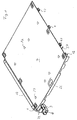
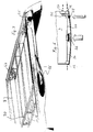
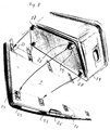
- FIG. 1 and 2 are exemplary embodiments of a perspective view multifunctional fastening device for objects in the trunk or Luggage compartment of a motor vehicle are shown.
- the device is designed as a multi-function carrier device.
- a board-shaped flat loading platform 7 is used as the load carrier.
- the load carrier consists of cross beams 8.
- the respective load carrier (Loading platform 7, cross member 8) is on the side extending in the vehicle longitudinal direction Telescopic carriers 13 stored.
- Each of the two telescopic supports 13 has telescopic support rails, which consist of rail parts inserted into each other, the multifunction carrier installed in the luggage compartment of the vehicle can be pulled out of the vehicle in reverse.
- the loading platform 7 and the Cross members 8 are mounted on the respective outer carrier rail 1.
- the guide grooves 4 of the two support rails 1 are on the inside of the telescopic carrier 13 and face each other in the installed state.
- the loading platform 7 is inserted and stored in the guide grooves 4, such as it is shown in FIG. 1. By means of sliding elements (sliding blocks) 47, the loading platform can 7 can be moved in the grooves 4.
- Fixing means 5, 6, which can be designed as depressions, for example, intended.
- these fixing means 5, 6 are located in the area of the guide groove 4 (FIG. 3).
- FIG. 6 there are at the rear end of the loading platform 7 engaging means 57, which by spring force in the corresponding fixing means 6 (depressions of the carrier rails 1) are pressed in.
- the loading platform 7 becomes fixed to the carrier rails 1 during transport connected.
- each end piece has an engagement means 11, for example in the form of one in the End piece 36 sliding locking element (locking stone).
- the locking element is acted upon by a locking spring 37 and in the locking position (Fig. 4 (A)) pressed.
- the engaging means 11 comes into engagement with a respective fixing means 5 (recess) on the carrier rail 1. This is the respective cross member 8 in the longitudinal direction in certain positions on the support rails 1 fixed.
- Push button 35 disengaged the engagement means 11 from the fixing means 5.
- a release bevel 38 which cooperates with the engagement means 11 in such a way that when the Push button 35 (Fig. 4 (B)) engages the means 11 against the force of the locking spring 37 is brought out of engagement with the fixing means 5 designed as a recess.
- the Cross members 8 can then in the longitudinal direction of the support rails on the support rails 1 are moved along the grooves 4 and detached from the carrier rails 1 or in other positions with the support rails 1, wherein again the corresponding engagement means 11 in the end pieces 36 with the fixing means 5 (depressions) on the support rails.
- Fig. 3 is located the locking of the support rails at the rear end of the telescopic support 13 and has a push button 38.
- the lock can be designed in the same way be like the locking device shown in FIG. 4.
- a locking stone (Locking element) 70 by means of spring force (compression spring 71) in a locking position are pressed in which the carrier rail 1 against pulling out on the telescopic carrier 13 is secured (detailed illustration (A).
- the lock By means of the manually operable Push button 38, the lock can be released so that the support rails 1 together can be pulled out with the platform 7 or the cross members 8 (Detail view (B)).
- the pushbutton 38 can be used to unlock the slope 72, which cooperates with the locking block 70, moved in the manner be that this against the force of the locking spring 71 from the locking position brought.
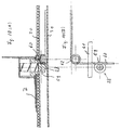
- the unlocking is by means of a manually operated Push button 40 against the restoring force of a restoring spring 67 and the locking force a locking spring 69 causes.
- a locking spring 69 In the locked state, which in the Figures 9 (B) and (C) are shown, engage by the locking spring 9 Locking leg 65 in correspondingly shaped lateral locking grooves a locking bolt 66, which in the locked state in the recess 64 of the Vehicle floor is inserted.
- the locking bolt 66 is about a pivot axis 69 swiveling.
- the locking button 40 is on the locking bolt 66 rotatably connected crank 68 articulated.
- the locking bolt 66 By the force of the return spring 67, which acts on the push button 40, the locking bolt 66 in the in the figures shown position held, in which the two locking legs 65 by the Locking spring 69 are pressed into the corresponding locking grooves.
- the locking bolt 66 pivoted about the pivot axis 69, so that the locking leg 65 are pressed out of the locking grooves and on a smooth the cylindrical surface of the locking bolt.
- the locking bolt can then be pulled out of the recess 64.
- the locking leg 65 by the force of the locking spring 69 snap into the locking grooves so that the rear end of each Telescopic carrier 13 is secured against pulling out.
- At least one attachment element 14 may be provided (FIGS. 5 (A) to (G)).
- the attachment element 14 can in its unlocked or unlocked position along the cross member 8 be moved. By locking or locking it can be in a respective suitable position on the cross member 8 are fixed.
- Located on the attachment element 14 a holding device 16.
- the holding device 16 is around one for longitudinal expansion of the cross member 8 vertically in particular horizontally extending axis 15 mounted on the attachment element 14.
- the pivot axis 15 can from one on the clamping jaw 17 supported journals 76 are formed.
- the holding device can be within an acute swivel angle that is up to about 60 °, in particular about 40 ° can be pivoted.
- the pivoting of the holding device 16 can between a first lower position (Fig. 5 (B)), in which the holding device 16 is essentially a horizontal position, and an upper end position in which the holding device 16 can be pivoted upwards by the acute swivel angle.
- the holding device 16 forms part of the attachment element 14.
- a second part of the Attachment element 14 is a slidable part on the cross member 8, which is essentially is formed by jaws 17 and 18.
- the jaws 17, 18 are used for fixation of the attachment element 14, the clamping jaws being brought into a clamping position become. For moving the attachment element 14 along the cross member 8 this clamping position is released.
- the clamping jaws 18 are in particular horizontal Direction perpendicular to the extension of the cross member 8 movable on the attachment element 14 stored.
- Parallel guide webs 73 formed on the clamping jaws 18 (Fig. 5 (B)) are used to guide the jaws 17.
- To move the jaws 18 serves a manually actuable actuating element 20 in the form of a lever effect having flap.
- the actuating element 20 is pivotable about an axis 22 stored.
- a locking element 19 (Fig. 5 (B)) vertically movable to the longitudinal extent of the cross member 8.
- the locking element 19 also extends through the clamping jaws 18.
- the locking element 19 is preferably designed as a locking pin in the direction of its longitudinal axis 21 is movably mounted on the attachment element or the clamping jaws 17, 18.
- the pen-shaped Locking element 19 can be provided with a locking end 45 via a rear side a circuit board 74 defined locking level 46 (Fig. 5 (G)) beyond and behind this locking level 46 are moved out. In one from the front of the of the holding device 16 attached to the printed circuit board 74 are delimiting surfaces the holding device 16 and the jaw 17 sliding against each other.
- the locking end 45 (Fig. 5 (D)
- the holding device 16 in different Angular positions when pivoting about the pivot axis 15 (Fig. 5 (A), (B)) being held.
- arcuate recess or backdrop 75 may be provided through which the arrester 45 protrudes.
- the upper closed end of the arcuate recess 75 is in the horizontal positioning of the holding device 16 on the through the recess projecting pin-shaped locking element 19. That compared to the slit-shaped Recess 75 widened locking end 45 lies when clamping the clamping jaws 17, 18 on the cross member 8 on the rear side (locking plane 46) of the board 74 so that the clamping force is supported on the back of the board 74. At the same time this allows the holding device 16 in different angular positions when pivoting lock around the pivot axis 15.
- one or both ends of the arcuate recess 75 can also a pivoting of the holding device 16 down against one example provided in the area of the bearing pin 76 provided stop.
- a region that extends beyond the circular arc-shaped region of the recess 75 can also be used Swiveling of the holding device 16 take place when the lower end of this Recess is open.
- the axis 22 can which the actuating element 20 is pivotally mounted.
- the axis 22 can be formed on or attached to the locking element 19 Pen be formed. Due to the pin-shaped design of the locking element 19, this can rotatable about its longitudinal axis 21 on the attachment element or the fixed clamping jaws 17 be stored. This also makes the actuating element pivotable 20 around the longitudinal axis 21 of the locking element 19. Hereby the actuating surface 41 can be detached from the contact surface 43 and detached from it Be held apart.
- Holding elements are provided on the holding device 16 in order to hold different objects to be able to attach to the holding device.
- These holding elements can For example, consist of fixing screws 23 (Fig. 5 (E)), which on a fixing pin 50 are stored. It is sufficient if one of the two fixing screws 23 on a thread the fixing pin 50 is screwed on, while the other fixing screw with the Fixing pin is connected. Between the fixing screws 23 and stops 52 on the Holding device 16 can in particular springs wound around the fixing pin 50 Coil springs 51 may be provided. On the fixing pin 50 and between the stops 52 and the fixing screws 23 can fork ends of a front fork one Bicycle used and by tightening one of the two fixing screws 23 on the Holding device 16 are fixed. It is also possible to use support rods 25a for a saddle holder or support rods 25b for holding a handlebar of a bicycle (Fig. 2) on Fixing pin 50 or otherwise to store.
- one or more insertion openings 53 can be provided on the holding device 16 into which one or more support rods 24 for front wheel holders (FIG. 5 (F) and (G)) can be used.
- a front wheel 54 of a bicycle can be attached (Fig. 5 (F))).
- the holding device 16 can be in an upper or lower position the pivot axis 15 are pivoted so that the installation height of the holding device attached bike can be reduced.
- the holding rods can be pivoted, with Using the fixing screws 23, the handrails in any desired pivot position can be fixed.
- the handrails can be designed in such a way that they certain components of a bicycle or other object in the luggage compartment of the vehicle to be transported, can be firmly connected. This ensures safe storage of the object in the luggage compartment of the vehicle guaranteed while driving.
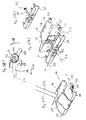
- the loading platform 7 shown in FIGS. 6, 7 and 8 can, as shown in FIG. are stored along their side edges in the mounting rails 1.
- the Side edges are preferably inserted into the longitudinal grooves 4 of the carrier rails 1.
- Means the sliding elements 47 (Fig. 1) is a simple displacement of the platform 7 in the Guide grooves 4 reached.
- the engagement means 57 Fig. 6
- a fixation of the Loading platform 7 achieved on the support rails 1 the engagement means 57 in the corresponding recesses (openings) 6 of the carrier rails 1 (Fig. 2 and 3) intervention.
- This locking of the loading platform 7 takes place by spring force, which on the engagement means 12 acts and they in the corresponding recesses 6 of the support rails presses.
- the engagement means 57 against the force of the locking spring from its engaged position Pulling out of the recesses 6 can be solved so that the loading platform along the guide groove 4 shifted in the carrier rails 1 or out of the carrier rail 1 can be removed.
- the push button movement is via a hinge mechanism 56 on the engagement means 57 on one or both side edges of the loading platform 7 transferred.
- a actuator 26 preferably provided on the rear of the loading platform 7 operated by hand.
- the movement of the flap, which is preferably designed as a manually operable flap Actuator 26 is over rods 34 with laterally protruding Transfer the rod ends 12 to the pushbuttons 38 of the carrier rail lock.
- the push button 38 Fig. 3 for unlocking the carrier rail lock especially operated by indentation.
- the carrier rails 1 released from their locked position with the telescopic supports 13 so that the support rails 1 can be pulled out telescopically from the luggage compartment. It is possible with the help of an actuating device 26 at the end of the loading platform To release carrier rail locks together.
- the carrier rail locks can be designed in the manner related above was described with FIG. 3.
- the loading platform 7 is supported by an upper plate 30 and a lower plate 31, the two plates being separated by spacers 32 kept apart from each other.
- the spacers 32 can be rectangular hollow profiles form.
- the plates 30 and 31 and the spacers 32 can be made in one piece from an extruded profile by cutting to length from an extruded profile be educated.
- the platform 7 preferably consists of light metal in particular Aluminum.
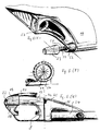
- the loading platform 7 can have fixation adapters, for example in the form of depressions 27 in the surface of the loading platform exhibit.
- Feet 28 (FIG. 8) which fit on the Bottom of containers 29 are arranged.
- the locking elements 60 are under spring tension, so that when inserting the feet 28 in the Indentations 27, the locking elements 60 are automatically pressed into the locking grooves 59.
- four feet 28, which may be sprung are stored (Fig. 10 (A)), may be provided.
Abstract
Description
Die Erfindung betrifft eine Vorrichtung nach dem Oberbegriff des Patentanspruches 1.The invention relates to a device according to the preamble of
Eine derartige aus der DE 296 08 955 U1 bekannte Vorrichtung weist zwei Führungselemente auf, in denen teleskopartig verschiebbare Führungsschienen vorgesehen sind. Die Führungselemente sind durch Verbindungselemente für eine parallele Anordnung miteinander verbunden. Die Befestigung dieser Führungseinheit erfolgt mit den Verbindungselementen mittels Schrauben oder anderer Befestigungsmittel am Boden des Laderaumes. Die Verbindungselemente, mit denen die teleskopierbaren Führungselemente bzw. Trägerschienen am Boden des Laderaumes befestigt werden, verlaufen quer zur Fahrzeugslängsrichtung. Die bekannte Vorrichtung ist für eine ständige Befestigung im Kraftfahrzeug bestimmt, woraus eine bleibende Umgestaltung des Gepäckraumes sich ergibt.Such a device known from DE 296 08 955 U1 has two guide elements on, in which telescopically movable guide rails are provided. The guide elements are by connecting elements for a parallel arrangement connected with each other. This guide unit is fastened with the connecting elements using screws or other fasteners on the floor of the cargo area. The connecting elements with which the telescopic guide elements or carrier rails are attached to the floor of the cargo space, extend transversely to Vehicle longitudinal direction. The known device is for permanent attachment in Motor vehicle determines what a permanent redesign of the luggage space results.
Aufgabe der Erfindung ist es, eine Vorrichtung der eingangs genannten Art zu schaffen, die bei einfacher Handhabung ohne karosserieseitige Änderungen im Gepäckraum eines Kraftfahrzeuges eingesetzt werden können.The object of the invention is to provide a device of the type mentioned in the introduction, the one with simple handling without changes to the body in the luggage compartment Motor vehicle can be used.
Diese Aufgabe wird erfindungsgemäß durch die kennzeichnenden Merkmale des Patentanspruches
1 gelöst.This object is achieved by the characterizing features of the
Hierzu besitzt die ausziehbare Trägereinrichtung zwei in Fahrzeuglängsrichtung verlaufende teleskopierbare Trägerschienen, die entlang den beiden Seitenbegrenzungen des Gepäckraumes des Kraftfahrzeugs angeordnet werden. Jede der beiden teleskopierbaren Trägerschienen wird in einem länglichen, sich in Fahrzeuglängsrichtung erstreckenden Teleskopträger geführt. Jeder der beiden Teleskopträger ist an der Fahrzeugkarosserie oder an karosseriefesten Fahtrzeugteilen lösbar verriegelt. Ferner sind an den Trägerschienen Fixiermittel zum lösbaren Befestigen unterschiedlicher Lastträger, beispielsweise von staubförmigen quer zur Fahrzeuglängsrichtung verlaufenden Querträgern oder einer Ladeplattform vorgesehen. Die Lastträger sind so ausgebildet, daß an ihnen Gegenstände befestigt werden können. For this purpose, the extendable carrier device has two extending in the vehicle longitudinal direction telescopic support rails that run along the two side boundaries of the Luggage compartment of the motor vehicle can be arranged. Each of the two telescopic Carrier rails are in an elongated, extending in the vehicle longitudinal direction Telescopic carrier led. Each of the two telescopic carriers is on the vehicle body or releasably locked to body-fixed vehicle parts. Furthermore, are on the support rails Fixing means for releasably attaching different load carriers, for example of dust-like cross members running transverse to the vehicle's longitudinal direction or a loading platform. The load carriers are designed so that objects can be attached to them.
Um die Teleskopträger, an denen die teleskopierbaren Trägerschienen geführt sind, mit der Fahrzeugkarosserie bzw. den karosseriefesten Fahrzeugteilen zu verbinden, können die Teleskopträger an ihren beiden Enden lösbare Verriegelungen aufweisen. Die jeweilige teleskopierbare Trägerschiene kann aus einer außen liegenden Trägerschiene und einer innen liegenden Trägerschiene bestehen, wobei die innen liegende Trägerschiene mit dem Teleskopträger fest verbunden ist und die außen liegende Trägerschiene die Fixiermittel für die Lastträger aufweist. Zwischen diesen beiden Schienen kann eine weitere Schiene zur Verlängerung des Teleskopsauszugs vorgesehen sein. Derartige Teleskopauszüge sind bekannt.To the telescopic carrier on which the telescopic carrier rails are guided with to connect the vehicle body or the body-fixed vehicle parts the telescopic supports have releasable locks at both ends. The respective telescopic carrier rail can consist of an external carrier rail and an inner carrier rail exist, the inner carrier rail is firmly connected to the telescopic carrier and the outer carrier rail Has fixing means for the load carrier. One can be between these two rails additional rails can be provided to extend the telescopic extension. Such Telescopic extensions are known.
Die Fixiermittel können in der Weise ausgebildet sein, daß sie zur Befestigung von Querträgern in verschiedenen Positionen in Fahrzeuglängsrichtung an der äußeren Trägerschiene lösbar befestigt werden können. Hierbei können auch zwei oder mehr Querträger in bestimmten Abständen voneinander an den Trägerschienen befestigt werden. Ferner kann die jeweils außen liegende Trägerschiene eine Längsnut, die sich in Fahrzeuglängsrichtung erstreckt, aufweisen. Diese Längsnut kann zum Verschieben der Querträger in Längsrichtung entlang der Trägerschienen beim Auffinden der entsprechenden Position dienen. Ferner kann die Längsnut zur Lagerung der Plattform dienen, wobei die beiden Längskanten der Plattform in die Führungsnuten der beiden Trägerschienen eingesetzt ist. Auch für die Plattform können Fixiermittel vorgesehen sein, um die Plattform an der außen liegenden Trägerschiene zu befestigen.The fixing means can be designed in such a way that they can be used for fastening Cross members in various positions in the vehicle longitudinal direction on the outer support rail can be detachably attached. Two or more crossbeams can also be used here are attached to the support rails at certain intervals from one another. Furthermore, the respective outer carrier rail can have a longitudinal groove that extends in the longitudinal direction of the vehicle extends. This longitudinal groove can be used to move the Cross members in the longitudinal direction along the support rails when finding the corresponding Serve position. Furthermore, the longitudinal groove can serve to support the platform, the two longitudinal edges of the platform into the guide grooves of the two support rails is inserted. Fixing means can also be provided for the platform to attach the platform to the outer support rail.
Die Arretier- und Verriegelungseinrichtungen, mit denen die Teleskopträger an der Karosserie bzw. den karosseriefesten Teilen lösbar verbunden werden und mit denen die lösbare Befestigung des jeweiligen Lastträgers an den Trägerschienen im Bereich der Fixiermittel erfolgt, können von Hand betätigbar sein. Hierdurch ist es möglich, ohne Spezialwerkzeuge die Befestigungsvorrichtung im Kraftfahrzeug, welches ein auf dem Markt befindliches Kraftfahrzeug, beispielsweise Kombifahrzeug, Caravan, Minivan und dergl. sein kann, lösbar je nach Bedarf zu befestigen. The locking and locking devices with which the telescopic carrier on the body or the body-fixed parts are releasably connected and with which the Detachable attachment of the respective load carrier to the carrier rails in the area of Fixing agent takes place, can be operated by hand. This makes it possible without Special tools the fastening device in the motor vehicle, which one on the Motor vehicle on the market, for example station wagon, caravan, minivan and the like. Can be releasably attached as required.
Am jeweiligen Lastträger (Querträger, Ladeplattform) können ebenfalls von Hand ohne zusätzliches Werkzeug lösbare Verriegelungen vorgesehen sein, um die zu transportierenden Gegenstände mit dem Lastträger fest zu verbinden.On the respective load carrier (cross member, loading platform) can also be done by hand without Additional tool releasable locks can be provided in order to be transported Connect objects firmly to the load carrier.
Hierzu kann am Querträger wenigstens ein entlang dem Querträger verschiebbares Aufsatzelement vorgesehen sein, das in verschiedenen Positionen längs dem Querträger, insbesondere durch Klemmsitz, arretierbar ist. Am Aufsatzelement ist eine Halteeinrichtung vorgesehen, die um eine zur Querträgerlängsausdehnung quer, insbesondere senkrecht und in horizontaler Richtung verlaufende Achse schwenkbar gelagert ist. Die Halteeinrichtung ist hierzu innerhalb eines spitzen Schwenkwinkelbereichs schwenkbar und kann zumindest in den beiden Endstellungen des spitzen Schwenkwinkelbereichs am Aufsatzelement mittels ebenfalls von Hand betätigbarer Verriegelungsmittel fixiert werden. Ein derartiges Aufsatzelement ist auch in bevorzugter Weise anwendbar bei einem Querträger, der an einer beispielsweise außen am Fahrzeug, insbesondere am Dach, vorgesehenen Trägereinrichtung zur Anwendung kommt. Mit diesem Aufsatzelement können Gegenstände verschiedenster Art, z.B. Fahrräder, Ski und andere sich in Längsrichtung des Fahrzeugs erstreckende Geräte und Gegenstände an wenigstens zwei Querträgern lösbar befestigt werden.For this purpose, at least one attachment element which can be displaced along the cross member can be on the cross member be provided in different positions along the cross member, can be locked in particular by a clamp fit. There is a holding device on the attachment element provided, which is transverse to the cross member longitudinal expansion, in particular vertically and horizontally extending axis is pivotally mounted. The For this purpose, the holding device can be pivoted within an acute swivel angle range and can at least in the two end positions of the acute swivel angle range fixed to the attachment element by means of locking means which can also be operated by hand become. Such an attachment element can also be used in a preferred manner a cross member, for example on the outside of the vehicle, in particular on Roof, provided support device is used. With this attachment element All kinds of objects, e.g. Bicycles, skis and others get in Devices and objects extending at least in the longitudinal direction of the vehicle two cross members can be detachably attached.
Um das Aufsatzelement in verschiedenen Positionen längs dem Querträger zu fixieren, können am Aufsatzelement zwei Klemmbacken vorgesehen sein, von denen wenigstens einer beweglich am Aufsatzelement gelagert ist. Mit Hilfe einer von Hand betätigbaren, vorzugsweise mit Hebelwirkung wirkenden Handbetätigungseinrichtung kann der verschiebbare Klemmbacken aus seiner gelösten Stellung in die Klemmstellung verbracht werden. Das wie eine Klappe ausgebildete Betätigungselement kann eine im Querschnitt gekrümmte Betätigungsfläche aufweisen, welche mit dem beweglichen Klemmbacken in Anlage gebracht wird. Um den Klemmbacken in seine Klemmstellung zu bringen, wird die Betätigungsfläche so gedreht, daß ihr Krümmungsradius sich vergrößert, wodurch der Klemmbacken in die Klemmstellung bewegt wird. Der an dem Betätigungselement vorgesehene klappenförmige Hebelarm, welcher von Hand verschwenkt werden kann, ist wesentlich größer als der Hebelarm, mit welchem die Betätigungsfläche auf den Klemmbacken wirkt. In der Klemmstellung wird die Betätigungseinrichtung durch Selbsthalteeffekt bei heruntergeklapptem Hebelteil des Betätigungselementes gehalten.To fix the attachment element in different positions along the cross member, can be provided on the top element two jaws, of which at least one is movably mounted on the attachment element. With the help of a manually operated, The movable actuating device, preferably acting with leverage, can Jaws moved from its released position to the clamping position become. The actuating element designed like a flap can have a cross section have curved actuating surface, which with the movable jaws is brought into investment. To bring the jaws into their clamping position, the operating surface is rotated so that its radius of curvature increases, whereby the clamping jaw is moved into the clamping position. The one on the actuator provided flap-shaped lever arm, which can be pivoted by hand can, is much larger than the lever arm with which the actuating surface acts on the jaws. In the clamped position, the actuator is activated Self-holding effect held when the lever part of the actuating element is folded down.
Um die Halteeinrichtung in einer der beiden Entstellungen des Schwenkwinkels am Aufsatzelement zu fixieren, können am Aufsatzelement entsprechende Anschläge vorgesehen sein, welche die Halteeinrichtung unbeweglich in der jeweiligen Endstellung halten. Hierzu kann wenigstens einer der Anschläge, welcher auch als Arretierelement zum Arretierung der Halteeinrichtung in einer Zwischenstellung dienen kann, beweglich am Aufsatzelement gelagert sein. Das Arretierelement ist hierzu bevorzugt stiftförmig ausgebildet und erstreckt sich senkrecht zur Längsausdehnung des Querträgers, insbesondere in horizontaler Ebene. Das Arretierelement ist hierbei in seiner axialen Richtung verschiebbar am Aufsatzelement gelagert. Zur Betätigung des Arretierelementes kann dieses mit dem Betätigungselement, mit welchem der bewegliche Klemmbacken betätigt wird, verbunden sein. Dies kann in der Weise geschehen, daß das Betätigungselement des Klemmbackens schwenkbar an einem Ende des stiftförmigen Arretierelementes angeordnet ist, wobei die Schwenkachse des Betätigungselementes senkrecht zur Stiftachse des Arretierelementes verläuft. Das bedeutet, daß mit Hilfe des Betätigungselementes für den beweglichen Klemmbacken auch das stiftförmig ausgebildete Arretierelement in und außer Arretierposition gebracht werden kann.To the holding device in one of the two distortions of the pivot angle on the attachment element to fix, appropriate stops can be provided on the attachment element be, which hold the holding device immovably in the respective end position. For this purpose, at least one of the stops, which is also used as a locking element for locking can serve the holding device in an intermediate position, movable on Attachment element can be stored. For this purpose, the locking element is preferably pin-shaped and extends perpendicular to the longitudinal extent of the cross member, in particular in a horizontal plane. The locking element is in its axial direction slidably mounted on the attachment element. Can be used to actuate the locking element this with the actuating element with which the movable jaws are actuated will be connected. This can be done in such a way that the actuator of the jaw pivotable at one end of the pin-shaped locking element is arranged, the pivot axis of the actuating element perpendicular to Pin axis of the locking element runs. That means that with the help of the actuator also the pin-shaped locking element for the movable jaws can be brought in and out of locking position.
Die Halteeinrichtung wird normalerweise in einer etwa horizontalen Endstellung gehalten und kann in einer oberen oder unteren Endstellung verstellbar bzw. verschwenkbar am Aufsatzelement gelagert sein. Dadurch, daß die Halteeinrichtung in eine untere oder obere Endstellung verschwenkbar ist, kann die Transporthöhe des jeweiligen Gegenstandes, beispielsweise eines Fahrrades, verringert werden. Auch kann der zu transportierende Gegenstand in eine günstige Transportstellung gebracht werden.The holding device is normally held in an approximately horizontal end position and can be adjusted in an upper or lower end position Attachment element can be stored. The fact that the holding device in a lower or upper end position is pivotable, the transport height of the respective object, for example, a bicycle. Also the one to be transported Object to be brought into a convenient transport position.
Die Halteeinrichtung ist in der Weise ausgebildet, daß unterschiedliche Halteelemente, mit denen verschiedene Gegenstände befestigt werden können, an der Halteeinrichtung vorgesehen sind. Beispielsweise können Halteelemente gegebenenfalls mit Fixierschrauben, mit denen Gabelenden einer Vorderradgabel eines Fahrrades, ein Vorderradhalter oder Haltestangen und andere Halteelemente befestigt werden können, vorgesehen sein.The holding device is designed in such a way that different holding elements, with which various objects can be attached to the holding device are provided. For example, retaining elements can optionally be used with fixing screws, with the fork ends of a front fork of a bicycle, a front wheel holder or holding rods and other holding elements can be attached be.
Anstelle der Querträger kann als Lastträger eine Ladeplattform, die an ihren beiden in Fahrzeuglängsrichtung verlaufenden Seitenkanten in die Tragschienen einsetzbar ist, vorgesehen sein. An der Ladeplattform ist ebenfalls eine von Hand betätigbare Verriegelungseinrichtung vorgesehen, um für den Transport die Ladeplattform fest mit den Trägerschienen zu verbinden. Die Seitenkanten der Ladeplattform können in die Längsnuten der Trägerschienen für den Transport eingesetzt sein. In diesen Längsnuten kann die Ladeplattform bis in die endgültige Transportstellung verschoben werden, wobei die Verriegelung durch Federkraft selbsttätig in entsprechende Fixiermittel an den Trägerschienen einrastet. An der Ladeplattform können zur Fixierung der zu transportierenden Gegenstände Fixiermittel vorgesehen sein. Diese können in Form von Vertiefungen ausgebildet sein, in die Füße von Behältern mit Federkraft selbsttätig arretierbar einsetzbar sind. Mit Hilfe einer von Hand betätigbaren zentralen Betätigungseinrichtung können die Arretierungen für die Behälterfüße gegen die arretierende Federkraft wieder gelöst werden.Instead of the crossbeam, a loading platform can be used as a load carrier, which can Side edges running in the longitudinal direction of the vehicle can be inserted into the mounting rails, be provided. A manually operated locking device is also on the loading platform provided to secure the loading platform to the support rails for transport connect to. The side edges of the loading platform can fit into the longitudinal grooves the carrier rails can be used for transport. Can in these longitudinal grooves the loading platform is moved to the final transport position, the Locking by spring force automatically in appropriate fixation means on the support rails snaps into place. On the loading platform can be used to fix the to be transported Objects fixative may be provided. These can be in the form of recesses be designed to be automatically lockable in the feet of containers with spring force are. With the help of a manually operated central actuation device can lock the container feet against the locking spring force again be solved.
Die Ladeplattform kann aus einer oberen und einer unteren Platte, welche parallel zueinander liegen und dazwischen angeordneten Abstandhaltern, gebildet sein. Durch die Abstandhalter, welche bevorzugt als Rechteckhohlprofile in Stabform ausgebildet sind, wird eine ausreichende Festigkeit der Plattform erreicht. Die beiden Platten und die Abstandhalter können aus relativ dünnem Material hergestellt sein, so daß die Plattform ein nur geringes Gewicht aufweist, jedoch eine ausreichende Festigkeit für den sicheren Transport der Gegenstände, insbesondere Behälter, gewährleistet. Die Plattform kann in bevorzugter Weise aus Leichtmetall, insbesondere Aluminium, hergestellt sein, wobei sie einstückig aus einem Strangpreßprofil gebildet ist.The loading platform can consist of an upper and a lower plate, which are parallel to each other lie and spacers arranged therebetween. Through the Spacers, which are preferably designed as rectangular hollow profiles in rod form, sufficient strength of the platform is achieved. The two plates and the spacers can be made of relatively thin material, so that the platform has only a low weight, but sufficient strength for the safe Transport of objects, especially containers, guaranteed. The platform can be in preferably be made of light metal, in particular aluminum, wherein it is formed in one piece from an extruded profile.
In vorteilhafter Weise wird durch die Erfindung ein multifunktionell einsetzbares Lade- und Transportsystem für die Anordnung in einem Gepäckraum eines Kraftfahrzeuges geschaffen. Der Einbau und das Herausnehmen dieses Transportsystems aus dem Fahrzeug gestaltet sich einfach, da die hierzu vorgesehenen Arretier- und Verriegelungseinrichtungen leicht von Hand lösbar sind. Werkzeuge sind hier nicht erforderlich. Die Lastträger, insbesondere in Form von Querträgern oder in Form einer Ladeplattform, sind ausziebar am teleskopierbaren Trägerschienensystem gelagert, so daß ein leichtes Beladen in ausgezogener Stellung ermöglicht wird. Bei in Transportstellung eingeschobener Stellung der Trägerschienen werden diese insbesondere an den Teleskopträgern, die am Fahrzeugaufbau lösbar befestigt sind, verriegelt, so daß ein sicherer Transport während des Fahrbetriebs des Fahrzeugs erreicht wird.Advantageously, a multifunctional charging and Transport system for arrangement in a luggage compartment of a motor vehicle created. The installation and removal of this transport system from the Vehicle is simple because the locking and locking devices provided for this purpose are easily removable by hand. Tools are not required here. The load carriers, in particular in the form of cross beams or in the form of a loading platform, are extendable mounted on the telescopic support rail system, making it easy Loading in the extended position is made possible. When inserted in the transport position Position of the support rails, in particular on the telescopic supports, which are releasably attached to the vehicle body, locked, so that safe transport is reached while the vehicle is in operation.
Anhand der Figuren wird an Ausführungsbeispielen die Erfindung noch näher erläutert. Es zeigt:
- Fig. 1:
- ein Ausführungsbeispiel der Erfindung mit einer Ladeplattform als Lastträger;
- Fig. 2:
- ein weiteres Ausführungsbeispiel der Erfindung mit stabförmigen Querträgern als Lastträger;
- Fig. 3:
- ein Endstück eines Teleskopträgers;
- Fig. 4(A,B)
- ein Ausführungsbeispiel für ein von Hand betätigbares Verriegelungselement zur Fixierung eines Querträgers an den Trägerschienen und zur Verriegelung der Trägerschienen am Teleskopträger:
- Fig. 5(A-G):
- ein Ausführungsbeispiel für ein auf einen Querträger aufsetzbares Aufsatzelement;
- Fig. 6:
- eine Draufsicht auf eine Ladeplattform mit Verriegelungseinrichtungen;
- Fig. 7:
- in perspektivischer Ansicht den Aufbau eines Ausführungsbeispiels einer Ladeplattform;
- Fig. 8:
- in perspektivischer Darstellung die Oberseite einer Ladeplattform;
- Fig. 9(A-C):
- Ausführungsbeispiele für karosseriefeste Bauteile, mit welchen die jeweiligen Enden eines Teleskopträgers lösbar an der Fahrzeugkarosserie, insbesondere im Gepäckraum, befestigbar sind, wobei Fig. 9(A) die lösbare Befestigung des vorderen Endes in Seitenansicht und die Figuren 9(B) in rückwärtiger und 9(C) in seitlicher Ansicht die lösbare Befestigung am hinteren Ende zeigen; und
- Fig. 10(A,B)
- eine Seitenansicht und eine Draufsicht in schnittbildlicher Darstellung für Befestigungsmittel, mit denen Behälter an einer Plattform lösbar fixiert werden können.
- Fig. 1:
- an embodiment of the invention with a loading platform as a load carrier;
- Fig. 2:
- a further embodiment of the invention with rod-shaped cross members as load carriers;
- Fig. 3:
- an end piece of a telescopic support;
- Fig. 4 (A, B)
- An exemplary embodiment of a locking element which can be actuated by hand for fixing a cross member to the carrier rails and for locking the carrier rails to the telescopic carrier:
- Fig. 5 (AG):
- an embodiment of an attachable element on a cross member;
- Fig. 6:
- a plan view of a loading platform with locking devices;
- Fig. 7:
- in perspective view the structure of an embodiment of a loading platform;
- Fig. 8:
- in perspective the top of a loading platform;
- Fig. 9 (AC):
- Exemplary embodiments for components fixed to the body, with which the respective ends of a telescopic carrier can be detachably fastened to the vehicle body, in particular in the luggage compartment, FIG. 9 (A) showing the releasable fastening of the front end in a side view and FIGS. 9 (B) in the rear and 9 (C) show the releasable attachment at the rear end in a side view; and
- Fig. 10 (A, B)
- a side view and a plan view in sectional view for fasteners with which containers can be releasably fixed to a platform.
In den Figuren 1 und 2 sind in perspektivischer Darstellung Ausführungsbeispiele einer
multifunktionellen Befestigungsvorrichtung für Gegenstände, die im Kofferraum bzw.
Gepäckraum eines Kraftfahrzeugs transportiert werden, dargestellt. Die Vorrichtung ist
als Multifunktionsträgervorrichtung ausgebildet. Beim Ausführungsbeispiel der Fig. 1
wird als Lastträger eine brettförmige ebene Ladeplattform 7 verwendet. Beim Ausführungsbeispiel
der Fig. 2 besteht der Lastträger aus Querträgern 8. Der jeweilige Lastträger
(Ladeplattform 7, Querträger 8) ist an seitlichen sich in Fahrzeuglängsrichtung erstreckenden
Teleskopträgern 13 gelagert. Jeder der beiden Teleskopträger 13 besitzt
teleskopierbare Trägerschienen, welche aus ineinander gesteckten Schienenteilen bestehen,
die bei im Gepäckraum des Fahrzeugs eingebauten Multifunktionsträger nach
rückwärts aus dem Fahrzeug ausgezogen werden können. Die Ladeplattform 7 bzw. die
Querträger 8 sind an jeweiligen äußeren Trägerschiene 1 gelagert. Diese äußeren Trägerschienen
1, welche direkt oder über eine Zwischenschiene an einer nicht näher dargestellten
fest am Teleskopträger 13 vorgesehenen Schiene verschiebbar gelagert ist,
besitzt eine sich in Fahrzeuglängsrichtung längs erstreckende Führungs- und Lagernut 4
(Figuren 1 und 3). Die Führungsnuten 4 der beiden Trägerschienen 1 befinden sich an
den Innenseiten der Teleskopträger 13 und sind im eingebauten Zustand einander zugekehrt.
In den Führungsnuten 4 wird die Ladeplattform 7 eingesetzt und gelagert, wie
es in der Fig. 1 gezeigt ist. Mittels Gleitelementen (Gleitsteine) 47 kann die Ladeplattform
7 in den Nuten 4 verschoben werden. 1 and 2 are exemplary embodiments of a perspective view
multifunctional fastening device for objects in the trunk or
Luggage compartment of a motor vehicle are shown. The device is
designed as a multi-function carrier device. 1
a board-shaped
An den Trägerschienen 1 sind ferner in Längsrichtung in bestimmten Abständen voneinander
Fixiermittel 5, 6, welche beispielsweise als Vertiefungen ausgebildet sein können,
vorgesehen. Beim dargestellten Ausführungsbeispiel befinden sich diese Fixiermittel 5, 6
im Bereich der Führungsnut 4 (Fig. 3). Wie aus der Fig. 6 zu ersehen ist, befinden sich
am rückwärtigen Ende der Ladeplattform 7 Eingriffsmittel 57, welche durch Federkraft in
die entsprechenden Fixiermittel 6 (Vertiefungen der Trägerschienen 1) eingedrückt werden.
Hierdurch wird die Ladeplattform 7 beim Transport fest mit den Trägerschienen 1
verbunden.On the support rails 1 are also in the longitudinal direction at certain distances from each other
Fixing means 5, 6, which can be designed as depressions, for example,
intended. In the exemplary embodiment shown, these fixing means 5, 6 are located
in the area of the guide groove 4 (FIG. 3). As can be seen from Fig. 6, there are
at the rear end of the
Zur Führung und Fixierung der Querträger 8 (Fig. 2) an den Trägerschienen 1 sind an
den Enden der Querträger 8 in Form von Gleitschuhen Endstücke 36 vorgesehen.
Querschnitte der Endstücke 36 sind in den Darstellungen der Figuren 4 (A) und (B) gezeigt.
Jedes Endstück besitzt ein Eingriffsmittel 11, beispielsweise in Form eines in dem
Endstück 36 verschiebbaren Verriegelungselements (Verriegelungsstein). Das Verriegelungselement
wird von einer Verriegelungsfeder 37 beaufschlagt und in die Verriegelungsstellung
(Fig. 4 (A)) gedrückt. Hierbei kommt das Eingriffsmittel 11 in Eingriff mit
einem jeweiligen Fixiermittel 5 (Vertiefung) an der Trägerschiene 1. Hierdurch wird der
jeweilige Querträger 8 in Längsrichtung in bestimmten Positionen an den Trägerschienen
1 fixiert. Um den Querträger zu lösen, wird mit Hilfe einer von Hand betätigbaren
Drucktaste 35 das Eingriffsmittel 11 außer Eingriff mit dem Fixiermittel 5 gebracht. Hierzu
kann an der Drucktaste 35 eine Entriegelungsschräge 38 vorgesehen sein, welche
mit dem Eingriffsmittel 11 in der Weise zusammenwirkt, daß beim Niederdrücken der
Drucktaste 35 (Fig. 4 (B)) das Eingriffsmittel 11 gegen die Kraft der Verriegelungsfeder
37 außer Eingriff mit dem als Vertiefung ausgebildeten Fixiermittel 5 gebracht wird. Die
Querträger 8 können dann in Längsrichtung der Trägerschienen an den Trägerschienen
1 entlang der Nuten 4 verschoben werden und von den Trägerschienen 1 gelöst werden
oder in anderen Positionen mit den Trägerschienen 1 fest verbunden werden, wobei
wiederum die entsprechenden Eingriffsmittel 11 in den Endstücken 36 mit den Fixiermitteln
5 (Vertiefungen) an den Trägerschienen in Eingriff kommen. To guide and fix the cross member 8 (Fig. 2) on the support rails 1 are on
the ends of the
In der in den Figuren 1 bis 3 dargestellten Transportstellung sind die Trägerschienen 1
an den Teleskopträgern 13 verriegelt. Wie aus der Fig. 3 zu ersehen ist, befindet sich
die Verriegelung der Trägerschienen am jeweils hinteren Ende des Teleskopträgers 13
und weist eine Drucktaste 38 auf. Die Verriegelung kann in der gleichen Weise ausgebildet
sein, wie die in der Fig. 4 dargestellte Verriegelungseinrichtung. Hierzu kann, wie
in den Detaildarstellungen (A) und (B) der Fig. 3 gezeigt ist, ein Verriegelungsstein
(Verriegelungselement) 70 mittels Federkraft (Druckfeder 71) in eine Verriegelungsstellung
gedrückt werden, in welcher die Trägerschiene 1 gegen Herausziehen am Teleskopträger
13 gesichert ist (Detaildarstellung (A). Mittels der von Hand betätigbaren
Drucktaste 38 kann die Verriegelung gelöst werden, so daß die Trägerschienen 1 zusammen
mit der Plattform 7 bzw. den Querträgern 8 herausgezogen werden können
(Detaildarstellung (B)). Auch hierbei kann durch die Drucktaste 38 eine Entriegelungsschräge
72, welche mit dem Verriegelungsstein 70 zusammenwirkt, in der Weise bewegt
werden, daß dieser gegen die Kraft der Verriegelungsfeder 71 aus der Verriegelungsstellung
gebracht wird.In the transport position shown in FIGS. 1 to 3, the carrier rails 1
locked to the telescopic supports 13. As can be seen from Fig. 3, is located
the locking of the support rails at the rear end of the
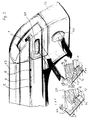
Die beiden sich in Fahrzeuglängsrichtung erstreckenden Teleskopträger 13, an denen
die Trägerschienen 1 gelagert sind, werden an karosseriefesten Fahrzeugteilen 2,3 befestigt.
Die Befestigung erfolgt in bevorzugter Weise jeweils am vorderen und am hinteren
Ende (Fig. 9(A) bis (C)). An den vorderen Enden der Teleskopträger 13 können Einschubteile
63 angeformt sein, die in entsprechende niederdrückbare Teile, beispielsweise
Drucktasten für Verzurrösen (Fig. 2 und 9(A)), eingeschoben werden können. An den
hinteren Enden (Fig. 9(B) und (C)) besitzen die Teleskopträger 13 Verriegelungsfüße 39,
welche eine Verriegelung tragen, die am Gepäckraumboden in Vertiefungen 64 verriegelt
werden kann. Die Verriegelung erfolgt in bevorzugter Weise ebenfalls durch Federkraft
(Verriegelungsfeder 65). Die Entriegelung wird mittels einer handbetätigbaren
Drucktaste 40 entgegen der Rückstellkraft einer Rückstellfeder 67 und der Verriegelungskraft
einer Verriegelungsfeder 69 bewirkt. Im Verriegelungszustand, welcher in den
Figuren 9(B) und (C) dargestellt ist, greifen von der Verriegelungsfeder 9 beaufschlagte
Verriegelungsschenkel 65 in entsprechend geformte seitliche Verriegelungsnuten an
einem Verriegelungsbolzen 66 ein, der im Verriegelungszustand in die Vertiefung 64 des
Fahrzeugbodens eingesteckt ist. Der Verriegelungsbolzen 66 ist um eine Schwenkachse
69 schwenkbar. Die Verriegelungstaste 40 ist mit einer am Verriegelungsbolzen 66
drehfest verbundenen Kurbel 68 angelenkt. Durch die Kraft der Rückstellfeder 67, welche
auf die Drucktaste 40 wirkt, wird der Verriegelungsbolzen 66 in der in den Figuren
gezeigten Stellung gehalten, in welcher die beiden Verriegelungsschenkel 65 durch die
Verriegelungsfeder 69 in die entsprechenden Verriegelungsnuten eingedrückt werden.
Beim Drücken der Drücktaste 40 entgegen der Kraft der Rückstellfeder 67 wird der Verriegelungsbolzen
66 um die Schwenkachse 69 geschwenkt, so daß die Verriegelungsschenkel
65 aus den Verriegelungsnuten herausgedrückt werden und an einer glatten
zylindrischen Oberfläche des Verriegelungsbolzens anliegen. Der Verriegelungsbolzen
kann dann aus der Vertiefung 64 herausgezogen werden. Um den Verriegelungsbolzen
66 in die verriegelte Position zu bringen, genügt es, den Bolzen in die Vertiefung 64 einzustecken,
wobei die Verriegelungsschenkel 65 durch die Kraft der Verriegelungsfeder
69 in die Verriegelungsnuten einschnappen, so daß das hintere Ende des jeweiligen
Teleskopträgers 13 gegen Herausziehen gesichert ist.The two
Zur Befestigung von Gegenständen insbesondere sperrigen Gegenständen an vorzugsweise
zwei Querträgem 8, die in Fahrzeuglängsrichtung im Abstand an den Träger
schienen in geeigneten Positionen fixiert sind, kann an einem jeweiligen Querträger 8
wenigstens ein Aufsatzelement 14 vorgesehen sein (Fig. 5(A) bis (G)). Das Aufsatzelement
14 kann in seiner entarretierten bzw. entriegelten Stellung längs dem Querträger 8
verschoben werden. Durch Arretierung bzw. Verriegelung kann es in einer jeweiligen
geeigneten Position am Querträger 8 fixiert werden. Am Aufsatzelement 14 befindet sich
eine Halteeinrichtung 16. Die Halteeeinrichtung 16 ist um eine zur Längsausdehnung
des Querträgers 8 senkrecht insbesondere horizontal verlaufende Achse 15 schwenkbar
am Aufsatzelement 14 gelagert. Die Schwenkachse 15 kann von einem am Klemmbakken
17 abgestützten Lagerzapfen 76 gebildet werden. Die Halteeinrichtung kann innerhalb
eines spitzen Schwenkwinkels, der bis etwa 60°, insbesondere ca. 40° betragen
kann, verschwenkt werden. Die Verschwenkung der Halteeinrichtung 16 kann zwischen
einer ersten unteren Position (Fig. 5(B)), in welcher die Halteeinrichtung 16 eine im wesentlichen
horizontale Lage einnimmt, und einer oberen Endstellung, in die die Halteeinrichtung
16 um den spitzen Schwenkwinkel nach oben verschwenkt werden kann, erfolgen.
Die Halteeinrichtung 16 bildet ein Teil des Aufsatzelements 14. Ein zweites Teil des
Aufsatzelements 14 ist ein am Querträger 8 verschiebbares Teil, das im wesentlichen
von Klemmbacken 17 und 18 gebildet wird. Die Klemmbacken 17, 18 dienen zur Fixierung
des Aufsatzelementes 14 , wobei die Klemmbacken in eine Klemmstellung gebracht
werden. Zum Verschieben des Aufsatzelements 14 entlang dem Querträger 8
wird diese Klemmstellung gelöst.For attaching objects especially bulky objects to preferably
two
Um das Arretieren des Aufsatzelementes 14 mit Klemmsitz am Klemmträger 8 zu erzielen,
kann einer der beiden Klemmbacken, nämlich der Klemmbacken 18, beweglich am
Aufsatzelement 14 gelagert sein. Der Klemmbacken 18 ist hierzu insbesondere in horizontaler
Richtung senkrecht zur Ausdehnung des Querträger 8 beweglich am Aufsatzelement
14 gelagert. Parallele an den Klemmbacken 18 angeformte Führungsstege 73
(Fig. 5 (B)) dienen zur Führung am Klemmbacken 17. Zur Verschiebung des Klemmbakkens
18 dient ein von Hand betätigbares Betätigungselement 20 in Form einer Hebelwirkung
aufweisenden Klappe. Das Betätigungselement 20 ist um eine Achse 22 schwenkbar
gelagert. Beim Verschieben des Klemmbackens 18 in die Klemmposition ist diese
Achse im wesentlichen horizontal bzw. parallel zur Längsausdehnung des Querträgers 8
angeordnet. Um diese Achse 22 ist eine Betätigungsfläche 41 vorgesehen, die im Querschnitt
einen sich vergrößernden Abstand zur Achse 22 aufweist (schnittbildliche Darstellung
der Fig. 5(C)). Die Betätigungsfläche 41 liegt an einer Anlagefläche 43 des Klemmbackens
18 an. Die Anlagefläche 43 besitzt einen im wesentlichen kreisförmigen Querschnitt.
Wenn das Betätigungselement 20 aus der gelösten Position (Fig. 5(C)) in Richtung
eines Pfeiles 42 (entgegen dem Uhrzeigersinn) verschwenkt wird, wird die an der
Anlagefläche 43 anliegende Betätigungsfläche 41 aus einem Bereich, der einen geringeren
Abstand von der Achse 22 aufweist, in einen Bereich verschwenkt, der einen größeren
Abstand zur Achse 22 besitzt. Hierdurch wird der Klemmbacken 18 in Richtung eines
Pfeiles 44 in die Klemmstellung gebracht, so daß das Aufsatzelement 14 am Querträger
8 in einer gewünschten Position durch Klemmsitz arretiert bzw. fixiert werden
kann (Fig. 5(G)).In order to achieve the locking of the
Am Aufsatzelement 14 insbesondere am festen Klemmbacken 17 ist ein Arretierelement
19 (Fig. 5 (B)) senkrecht zur Längsausdehnung des Querträgers 8 beweglich gelagert.
Das Arretierelement 19 erstreckt sich auch durch den Klemmbacken 18. Das Arretierelement
19 ist bevorzugt als Arretierstift ausgebildet, der in Richtung seiner Längsachse
21 beweglich am Aufsatzelement bzw. den Klemmbacken 17, 18 gelagert ist. Das stiftförmige
Arretierelement 19 kann mit einem Arretierende 45 über eine von einer Rückenseite
einer Platine 74 definierten Arretierungsebene 46 (Fig. 5 (G)) hinaus und hinter
diese Arretierungsebene 46 hinausbewegt werden. In einer von der Vorderseite der an
der Halteeinrichtung 16 befestigten Platine 74 gebildeten Berührungsebene liegen Begrenzungsflächen
der Halteeinrichtung 16 und des Klemmbackens 17 gleitend aneinander.
Durch das Arretierende 45 (Fig. 5 (D)) kann die Halteeinrichtung 16 in verschiedenen
Winkelpositionen beim Verschwenken um die Schwenkachse 15 (Fig. 5 (A), (B))
gehalten werden.On the
Um die horizontale Stellung der Halteeinrichtung 16 am Aufsatzelement 14 zu fixieren,
kann in der in der Platine 74 der Halteeinrichtung 16 um die Schwenkachse 15 eine
kreisbogenförmige Ausnehmung bzw. Kulisse 75 vorgesehen sein, durch die das Arretierende
45 ragt. Das obere geschlossene Ende der kreisbogenförmigen Ausnehmung
75 liegt bei horizontaler Positionierung der Halteeinrichtung 16 an dem durch die Ausnehmung
ragenden stiftförmigen Arretierelement 19 an. Das gegenüber der schlitzförmigen
Ausnehmung 75 verbreiterte Arretierende 45 liegt beim Festklemmen der Klemmbacken
17, 18 am Querträger 8 an der Rückseite (Arretierungsebene 46) der Platine 74
an, so daß die Klemmkraft an der Rückseite der Platine 74 abgestützt wird. Gleichzeitig
läßt sich hierdurch die Halteeinrichtung 16 in verschiedenen Winkelpositionen beim Verschwenken
um die Schwenkachse 15 arretieren.In order to fix the horizontal position of the holding
Wenn eines oder beide Enden der kreisbogenförmigen Ausnehmung 75 offen sind, kann
auch eine Verschwenkung der Halteeinrichtung 16 nach unten gegen einen beispielsweise
im Bereich des Lagerzapfens 76 vorgesehenen Anschlag vorgesehen werden.
Auch kann eine über den kreisbogenförmigen Bereich der Ausnehmung 75 hinaus erfolgende
Verschwenkung der Halteeinrichtung 16 erfolgen, wenn das untere Ende dieser
Ausnehmung offen ist.If one or both ends of the arcuate recess 75 are open, can
also a pivoting of the holding
Am anderen Ende des stiftförmigen Arretierungselementes 19 kann die Achse 22, um
welche das Betätigungselement 20 schwenkbar gelagert ist, vorgesehen sein. Die Achse
22 kann von einem an das Arretierelement 19 angeformten bzw. an diesem befestigten
Stift gebildet sein. Durch die stiftförmige Ausbildung des Arretierelements 19 kann dieses
um seine Längsachse 21 verdrehbar am Aufsatzelement bzw. den festen Klemmbacken
17 gelagert sein. Hierdurch wird ferner eine Verschwenkbarkeit des Betätigungselementes
20 um die Längsachse 21 des Arretierelementes 19 ermöglicht. Hierdurch
kann die Betätigungsfläche 41 von der Anlagefläche 43 gelöst werden und in dieser gelösten
Stellung voneinander gehalten werden.At the other end of the pin-shaped
An der Halteeinrichtung 16 sind Halteelemente vorgesehen, um unterschiedliche Gegenstände
an der Halteeinrichtung befestigen zu können. Diese Halteelemente können
beispielsweise aus Fixierschrauben 23 (Fig. 5 (E)) bestehen, welche an einem Fixierstift
50 gelagert sind. Es genügt, wenn eine der beiden Fixierschrauben 23 auf ein Gewinde
des Fixierstiftes 50 aufgeschraubt ist, während die andere Fixierschraube fest mit dem
Fixierstift verbunden ist. Zwischen den Fixierschrauben 23 und Anschlägen 52 an der
Halteeinrichtung 16 können Federn insbesondere um den Fixierstift 50 gewickelte
Schraubenfedern 51 vorgesehen sein. Auf dem Fixierstift 50 und zwischen den Anschlägen
52 und den Fixierschrauben 23 können Gabelenden einer Vorderradgabel eines
Fahrrades eingesetzt und durch Anziehen einer der beiden Fixierschrauben 23 an der
Halteeinrichtung 16 fixiert werden. Es ist auch möglich, Haltestangen 25a für einen Sattelhalter
oder Haltestangen 25b zum Halten eines Lenkers eines Fahrrades (Fig. 2) am
Fixierstift 50 oder sonstwie zu lagern.Holding elements are provided on the holding
Ferner können an der Halteeinrichtung 16 eine oder mehrere Einstecköffnungen 53 vorgesehen
sein, in die eine oder mehrere Haltestangen 24 für Vorderradhalter (Fig. 5 (F)
und (G)) eingesetzt werden können. Am oberen Ende der jeweiligen Vorderradhalterstange
kann ein Vorderrad 54 eines Fahrrades befestigt werden (Fig. 5 (F))).Furthermore, one or
Wie schon erläutert, kann die Halteeinrichtung 16 in eine obere oder untere Stellung um
die Schwenkachse 15 verschwenkt werden, so daß die Einbauhöhe des an der Halteeinrichtung
befestigten Fahrrades verringert werden kann. An den Fixierelementen der
Halteeinrichtung 16 können die Haltestangen schwenkbar angelenkt sein, wobei mit
Hilfe der Fixierschrauben 23 die Haltestangen in jeder gewünschten Schwenkposition
fixiert werden können. Die Haltestangen können in der Weise ausgebildet sein, daß sie
bestimmten Bauteilen eines Fahrrades oder eines anderen Gegenstandes, der im Gepäckraum
des Fahrzeugs transportiert werden soll, fest verbunden werden können.
Hierdurch wird eine sichere Lagerung des Gegenstandes im Gepäckraum des Fahrzeugs
während des Fahrbetriebes gewährleistet.As already explained, the holding
Die in den Fig. 6, 7 und 8 gezeigte Ladeplattform 7 kann, wie in der Fig.1 gezeigt ist,
entlang ihren Seitenkanten in den Tragschienen 1 gelagert werden. Hierzu können die
Seitenkanten bevorzugt in die Längsnuten 4 der Trägerschienen 1 eingesetzt sein. Mittels
der Gleitelemente 47 (Fig. 1) wird ein einfaches Verschieben der Plattform 7 in den
Führungsnuten 4 erreicht. Mit Hilfe der Eingriffsmittel 57 (Fig. 6), wird eine Fixierung der
Ladeplattform 7 an den Trägerschienen 1 erzielt, Hierbei können die Eingriffsmittel 57 in
die entsprechende Ausnehmungen (Öffnungen) 6 der Trägerschienen 1 (Fig. 2 und 3)
eingreifen. Diese Arretierung der Ladeplattform 7 erfolgt durch Federkraft, welche auf
die Eingriffsmittel 12 wirkt und sie in die entsprechenden Ausnehmungen 6 der Trägerschienen
drückt. Mit Hilfe einer von Hand betätigbaren Drucktaste 55 können die Eingriffsmittel
57 gegen die Kraft der Verriegelungsfeder aus ihrer Eingriffsstellung durch
Herausziehen aus den Ausnehmungen 6 gelöst werden, so daß die Ladeplattform entlang
der Führungsnut 4 in den Trägerschienen 1 verschoben bzw. aus der Trägerschiene
1 entnommen werden kann. Die Drucktastenbewegung wird über einen Gelenkmechanismus
56 auf das Eingriffsmittel 57 an einer oder beiden Seitenkanten der Ladeplattform
7 übertragen.The
Es ist jedoch auch möglich, unter Beibehaltung der Verriegelungsstellung der Eingriffsmittel
57 in den Ausnehmungen 6 der Trägerschienen die Trägerschienen 1 nach
Lösen der Verriegelung, mit welcher die Trägerschienen 1 an dem Teleskopträger 13
verriegelt sind, aus dem Gepäckraum des Fahrzeugs herauszuziehen. Hierzu wird eine
bevorzugt an der Rückseite der Ladeplattform 7 vorgesehene Betätigungseinrichtung 26
von Hand betätigt. Die Bewegung der vorzugsweise als handbetätigbare Klappe ausgebildeten
Betätigungseinrichtung 26 wird über Stangen 34 mit seitlich überstehenden
Stangenenden 12 auf die Drucktasten 38 der Trägerschienenverriegelung übertragen.
Durch die Bewegung des jeweiligen Stangenendes 12 oder Betätigungselementes am
Stangenende wird die Drucktaste 38 (Fig. 3) zum Entriegeln der Trägerschienenverriegelung
insbesondere durch Eindrücken betätigt. Hierdurch werden die Trägerschienen 1
aus ihrer mit den Teleskopträgern 13 verriegelten Stellung gelöst, so daß die Trägerschienen
1 aus dem Gepäckraum teleskopartig herausgezogen werden können. Es ist
möglich, mit Hilfe einer Betätigunseinrichtung 26 am Ende der Ladeplattform die entsprechenden
Trägerschienenverriegelungen gemeinsam zu lösen. Die Trägerschienenverriegelungen
können in der Weise ausgebildet sein, wie es oben im Zusammenhang
mit der Fig. 3 beschrieben wurde.However, it is also possible to maintain the locking position of the engagement means
57 in the
Wie aus der Fig. 7 zu ersehen ist, wird die Ladeplattform 7 von einer oberen Platte 30
und einer unteren Platte 31 gebildet, wobei die beiden Platten durch Abstandhalter 32
voneinander im Abstand gehalten werden. Die Abstandhalter 32 können Rechteckhohlprofile
bilden. Hierbei können die Platten 30 und 31 sowie die Abstandhalter 32 einstückig
aus einem Strangpreßprofil durch entsprechendes Ablängen aus einem Strangpreßprofil
gebildet sein. In bevorzugter Weise besteht die Plattform 7 aus Leichtmetall insbesondere
Aluminium.As can be seen from FIG. 7, the
Wie aus den Figuren 1 und 8 zu ersehen ist, kann die Ladeplattform 7 Fixierungsadapter,
beispielsweise in Form von Vertiefungen 27, in der Oberfläche der Ladeplattform
aufweisen. In diese Vertiefungen passen formschlüssig Füße 28 (Fig. 8), welche an der
Unterseite von Behältern 29 angeordnet sind. An den Füßen 28 befinden sich Rastnuten
59, in die entsprechende Rastelemente 60 beispielsweise in Form von quer verlaufenden
Stegen in den Vertiefungen 27 eingreifen können (Fig. 10 (A) und (B)). Die Rastelemente
60 stehen unter Federspannung, so daß beim Einsetzen der Füße 28 in die
Vertiefungen 27 die Rastelemente 60 selbstätig in die Rastnuten 59 gedrückt werden.
An jedem Behälter 29 können beispielsweise vier Füße 28, die gegebenenfalls gefedert
gelagert sind (Fig. 10(A)), vorgesehen sein. Hierdurch wird eine eindeutige Fixierung
eines jeden Behälter 29 an der Plattform 7 erreicht. Auf der Plattform 7 können mehrere
Vertiefungen 27 (Fixierungsadapter) in jeweils Viereranordnung für einen jeweiligen Behälter
29 vorgesehen sein. Mit Hilfe von zugeordneten Drucktasten 33 an der rückwärtigen
Kante der Plattform 7 können die Rastelemente 60 aus den Rastnuten 59 entfernt
werden, so daß die Behälter 29 von der Plattform 7 abgehoben werden können. Zur
Entriegelung wird die Drucktastenbewegung 33 beispielsweise über ein Schubstangensystem
61, welches an den mehreren Verriegelungselementen 60 angreift, auf die Verriegelungselemente
60 gegen die einrastende Federkraft übertragen, und die Verriegelungselemtne
60 werden aus den Verriegelungspositionen gelöst. Hierzu kann das in der
Fig. 8 schematisch dargestelltes Schubstangensystem 61, das an den quer verlaufenden
Abstandhaltern 32 (Fig. 7) gelagert ist und für die Fixierungsadapters eines Behälters
oder mehrere Behälter gleichzeitig betätigbar ist, vorgesehen sein. Auf das gemeinsame
Schubstangensystem 61 kann eine Verriegelungsfeder 62, welche ebenfalls an
einem der Abstandhalter 32 abgestützt ist, als Verriegelungskraft wirken.As can be seen from FIGS. 1 and 8, the
Claims (30)
dadurch gekennzeichnet,
characterized,
dadurch gekennzeichnet, daß
characterized in that
Applications Claiming Priority (2)
| Application Number | Priority Date | Filing Date | Title |
|---|---|---|---|
| DE19803210 | 1998-01-28 | ||
| DE1998103210 DE19803210C2 (en) | 1998-01-28 | 1998-01-28 | Device for fastening objects in the luggage compartment of a motor vehicle |
Publications (1)
| Publication Number | Publication Date |
|---|---|
| EP0939005A1 true EP0939005A1 (en) | 1999-09-01 |
Family
ID=7855898
Family Applications (1)
| Application Number | Title | Priority Date | Filing Date |
|---|---|---|---|
| EP99101300A Withdrawn EP0939005A1 (en) | 1998-01-28 | 1999-01-25 | Device for the fixing of articles in the luggage compartment of a motor vehicle |
Country Status (2)
| Country | Link |
|---|---|
| EP (1) | EP0939005A1 (en) |
| DE (1) | DE19803210C2 (en) |
Cited By (1)
| Publication number | Priority date | Publication date | Assignee | Title |
|---|---|---|---|---|
| EP2338738A2 (en) | 2009-12-17 | 2011-06-29 | Skoda Auto a.s. | Universal eccentric attachment device |
Families Citing this family (11)
| Publication number | Priority date | Publication date | Assignee | Title |
|---|---|---|---|---|
| DE10117122A1 (en) * | 2001-04-06 | 2001-10-04 | Audi Ag | Roof rack fitting for vehicle has permanently fitted side railing and with removable roof bars stored in grooves in the rear space of the vehicle |
| DE10228360A1 (en) * | 2002-06-25 | 2004-01-15 | Volkswagen Ag | Frame for positioning objects in a vehicle interior comprises bars for removable fixing onto the side walls, base and roof of the interior, and bars having quick-fastening locking devices for removably locking onto the first bars |
| DE10333630B4 (en) * | 2002-12-11 | 2004-10-21 | Uebler Gmbh | Fastening device for a transport good and its use in particular for a bicycle |
| DE10321890B4 (en) | 2003-05-07 | 2005-10-27 | Bos Gmbh & Co. Kg | Fastening device for a vehicle compartment |
| DE202004005126U1 (en) * | 2004-04-01 | 2005-08-18 | Hachenburg, Bruno | Bicycle rack and car with bicycle holder |
| DE102004041583A1 (en) * | 2004-08-26 | 2006-03-02 | Volkswagen Ag | Article e.g. cooling box, attaching device for use in vehicle, has adapter plate with pin section on its lower surface for locking in seat rail, and slider and locking device are placed between release and contact positions at article |
| DE102005030386B4 (en) * | 2005-06-29 | 2013-05-29 | Webasto Ag | Vehicle with a movable loading device |
| DE102007048894A1 (en) * | 2007-10-11 | 2009-04-16 | Sortimo Speedwave Gmbh | Detachable fastening system for cargo |
| FR2941419B1 (en) * | 2009-01-27 | 2011-04-22 | Peugeot Citroen Automobiles Sa | DEVICE FOR SUPPORTING A TWO-WHEEL TRANSPORT MEANS IN A REAR PART OF A VEHICLE'S HABITACLE |
| DE102009019866B4 (en) * | 2009-05-06 | 2023-05-25 | Rheinmetall Landsysteme Gmbh | Modular equipment carrier |
| DE102011112115A1 (en) * | 2011-09-02 | 2013-03-07 | GM Global Technology Operations LLC (n. d. Gesetzen des Staates Delaware) | Rail for storing multimedia terminal e.g. pocket personal computer (PC) in interior space of motor vehicle e.g. passenger car, has adapter including base portion in which clamping structure is provided |
Citations (5)
| Publication number | Priority date | Publication date | Assignee | Title |
|---|---|---|---|---|
| US5046913A (en) * | 1990-02-08 | 1991-09-10 | Domek Robert F | Quick install and remove slidable carrying table for vehicles |
| US5161700A (en) * | 1991-01-28 | 1992-11-10 | Prince Corporation | Adjustable storage system for a vehicle |
| DE4132954A1 (en) * | 1991-10-04 | 1993-04-08 | Helmut Walter Sterzel | DEVICE FOR DIVIDING A MOTOR VEHICLE BOX |
| EP0681942A1 (en) * | 1994-05-11 | 1995-11-15 | Framtid Kredit Und Finanz Anstalt | Holder device for a vehicle loading floor |
| DE29608955U1 (en) * | 1996-05-10 | 1996-09-26 | Jaehne Johannes | Loading device |
-
1998
- 1998-01-28 DE DE1998103210 patent/DE19803210C2/en not_active Expired - Fee Related
-
1999
- 1999-01-25 EP EP99101300A patent/EP0939005A1/en not_active Withdrawn
Patent Citations (5)
| Publication number | Priority date | Publication date | Assignee | Title |
|---|---|---|---|---|
| US5046913A (en) * | 1990-02-08 | 1991-09-10 | Domek Robert F | Quick install and remove slidable carrying table for vehicles |
| US5161700A (en) * | 1991-01-28 | 1992-11-10 | Prince Corporation | Adjustable storage system for a vehicle |
| DE4132954A1 (en) * | 1991-10-04 | 1993-04-08 | Helmut Walter Sterzel | DEVICE FOR DIVIDING A MOTOR VEHICLE BOX |
| EP0681942A1 (en) * | 1994-05-11 | 1995-11-15 | Framtid Kredit Und Finanz Anstalt | Holder device for a vehicle loading floor |
| DE29608955U1 (en) * | 1996-05-10 | 1996-09-26 | Jaehne Johannes | Loading device |
Cited By (2)
| Publication number | Priority date | Publication date | Assignee | Title |
|---|---|---|---|---|
| EP2338738A2 (en) | 2009-12-17 | 2011-06-29 | Skoda Auto a.s. | Universal eccentric attachment device |
| EP2338738A3 (en) * | 2009-12-17 | 2011-12-28 | Skoda Auto a.s. | Universal eccentric attachment device |
Also Published As
| Publication number | Publication date |
|---|---|
| DE19803210A1 (en) | 1999-08-05 |
| DE19803210C2 (en) | 2000-10-19 |
Similar Documents
| Publication | Publication Date | Title |
|---|---|---|
| DE2707893C2 (en) | Clamping device on a workbench or the like. | |
| EP0298382B1 (en) | Container for storage and transportation of especially bulk material, such as rubble, garbage, industrial waste and the like | |
| DE60310495T2 (en) | Portable workbench | |
| EP0754595B1 (en) | Variable quick fastening device for a roof luggage-case mounted on roof-rack transvers bars | |
| EP1522455B1 (en) | Device for securing loads in transportation units | |
| EP0939005A1 (en) | Device for the fixing of articles in the luggage compartment of a motor vehicle | |
| EP0019873A1 (en) | Transportation device for affixation to a car roof | |
| EP0737601B1 (en) | Device to avoid the sliding of objects during transport on vehicle load platforms | |
| EP2428406B1 (en) | Load holder with a pivoting sliding bearing | |
| DE102015108555A1 (en) | bike rack | |
| DE4338759A1 (en) | Bicycle carrier for roof of vehicle | |
| DE102009060366B4 (en) | Load carrier | |
| DE19838254C2 (en) | Transport chassis | |
| DE2908176C2 (en) | ||
| EP2765032B1 (en) | Load support with mobile load bearing parts mounted on a base support | |
| DE10241269B4 (en) | Transport platform with variable geometry for motorized two-wheeler, which is moved and locked via a linear guide system in the actual transport | |
| DE2944102C2 (en) | Log girders | |
| DE102008064332A1 (en) | transport device | |
| DE202018104929U1 (en) | retaining key | |
| DE102021207883B3 (en) | Carrier system for a two-wheeler | |
| EP2607176B1 (en) | Load support with a load bearing part and a supporting element | |
| DE4137576C2 (en) | Device for releasably holding objects on a vehicle seat | |
| DE102004008506B4 (en) | Device for transporting parts in motor vehicle body construction | |
| DE19615030C1 (en) | Retainer for foldable rear seat bench in vehicle | |
| DE102011007316B4 (en) | Fastening rail and fastening element |
Legal Events
| Date | Code | Title | Description |
|---|---|---|---|
| PUAI | Public reference made under article 153(3) epc to a published international application that has entered the european phase |
Free format text: ORIGINAL CODE: 0009012 |
|
| AK | Designated contracting states |
Kind code of ref document: A1 Designated state(s): AT DE ES FR GB IT SE |
|
| AX | Request for extension of the european patent |
Free format text: AL;LT;LV;MK;RO;SI |
|
| 17P | Request for examination filed |
Effective date: 19991015 |
|
| RAP1 | Party data changed (applicant data changed or rights of an application transferred) |
Owner name: HS-PRODUCTS KAROSSERIESYSTEME GMBH |
|
| AKX | Designation fees paid |
Free format text: AT DE ES FR GB IT SE |
|
| 17Q | First examination report despatched |
Effective date: 20020228 |
|
| GRAH | Despatch of communication of intention to grant a patent |
Free format text: ORIGINAL CODE: EPIDOS IGRA |
|
| STAA | Information on the status of an ep patent application or granted ep patent |
Free format text: STATUS: THE APPLICATION IS DEEMED TO BE WITHDRAWN |
|
| 18D | Application deemed to be withdrawn |
Effective date: 20030806 |