EP0681942A1 - Holder device for a vehicle loading floor - Google Patents
Holder device for a vehicle loading floor Download PDFInfo
- Publication number
- EP0681942A1 EP0681942A1 EP94107356A EP94107356A EP0681942A1 EP 0681942 A1 EP0681942 A1 EP 0681942A1 EP 94107356 A EP94107356 A EP 94107356A EP 94107356 A EP94107356 A EP 94107356A EP 0681942 A1 EP0681942 A1 EP 0681942A1
- Authority
- EP
- European Patent Office
- Prior art keywords
- holder device
- loading floor
- rods
- support bars
- locking means
- Prior art date
- Legal status (The legal status is an assumption and is not a legal conclusion. Google has not performed a legal analysis and makes no representation as to the accuracy of the status listed.)
- Withdrawn
Links
Images

Classifications
-
- B—PERFORMING OPERATIONS; TRANSPORTING
- B60—VEHICLES IN GENERAL
- B60P—VEHICLES ADAPTED FOR LOAD TRANSPORTATION OR TO TRANSPORT, TO CARRY, OR TO COMPRISE SPECIAL LOADS OR OBJECTS
- B60P7/00—Securing or covering of load on vehicles
- B60P7/06—Securing of load
- B60P7/08—Securing to the vehicle floor or sides
- B60P7/0892—Securing to the vehicle floor or sides by preventing lateral movement of the load, e.g. using stop blocks
Definitions
- the present invention is related to a device intended to be applied to a loading floor or platform of a vehicle for holding articles resting on such a loading floor.
- the device according to the invention is essentially characterized in that it comprises at least two rods intended to be positioned in a crossed configuration substantially parallelly to the loading floor at a predetermined distance therefrom, and disengageable locking means for rigidly securing said rods, at the respective ends thereof, to the loading floor.
- the holder device according to the invention allows, in an extremely simple, convenient and cheap way, to subdivide the area of the loading floor into receptacles containing the objects carried thereon, so as to prevent accidental and undesired displacements thereof during transportation.
- the dimensions, configuration and disposition of the receptacles thus defined may be readily adjusted by simply changing the relative positioning between the two rods, so as to match with those of the transported loads.
- the device thus performs an effective safety task and can easily suit loading floors or platforms of different sizes by employing rods of different length, or even of adjustable length, for instance by means of a telescopic structure thereof.
- the two rods may be readily released and stored anywhere, even on board the vehicle, with a negligible encumbrance.
- the holder device of the invention may be applied as an "after market" fitting to already existing vehicles, or may be directly provided by the vehicle manufacturer as an original equipment.
- the device can be conveniently employed with any transportation land vehicles (cars, trucks, railway vehicles), as well as with waterborne vessels and aircrafts.
- the disengageable locking means for fixing the rod ends to the loading floor of the vehicle may be conveniently designed so as to enable positioning of these rods according to different configurations of mutual crossing.
- These locking means may include for each rod, according to a preferred embodiment of the invention, a pair of support members adapted to be applied onto the loading floor of the vehicle generally perpendicularly to the rod and provided with respective quick anchoring elements for the ends thereof.
- These quick anchoring elements may be conveniently constituted by a plurality of side-by-side snap-in seats.
- the support members may for instance be comprised of modular bars, secured onto the vehicle loading floor either detachably or permanently.
- the support bars may be further separated from one another, and produced by cutting a set length of a continuous piece long enough to cover the maximum size contemplated for the loading floors of a set type of vehicles, or they may be interconnected at the respective adjacent ends thereof so as to define a monolithic frame substantially shaped like the perimeter of the loading floor of a specific vehicle.
- the holder device essentially comprises two rods 1, 2 arranged in a mutually perpendicular crossed configuration and in a superimposed condition onto a support frame 3, intended to be placed on the loading floor or platform P of a transportation vehicle, for instance of a car.
- the support frame 3 has a generally quadrangular shape and is constituted by a pair of bar elements 4 oriented parallelly to the rod 2 and supporting the ends 1a, 1b of the rod 1, and by a pair of bar elements 5 oriented parallelly to the rod 1 and supporting the ends 2a, 2b of the rod 2.
- the support bars 5 have a slightly greater height than the support bars 4, which allows the two rods 1, 2 to cross each other at two different levels. These levels shall be situated at a distance from the loading floor P of about a few centimeters.
- the respective support bars 4, 5 are provided with respective releasable locking means.
- These locking means which for the sake of simplicity of illustration are not shown in detail since generally within the knowledge of the man skilled in the art, may for instance be constituted by simple elastically yieldable seats formed on top of the bars 4, 5 and adapted to receive, by means of a quick snap fit, the corresponding ends of the rods 1, 2.
- the releasable locking means may be constituted by simple holes adapted to be engaged by spring pins carried by the ends of the rods 1, 2, or by bayonet coupling members, or still by any equivalent system.
- each bar 4, 5 is formed with a plurality of respective locking means arranged side by side along a row, such as diagrammatically shown by dotted lines 4a, 5a.
- the spaces delimited between the rods 1, 2 and the support bars 4, 5 define, with the loading floor P, receptacles R for containing and holding objects carried on the floor P.
- the size of the receptacles R can be readily adjusted simply varying the mutual positioning between the rods 1, 2 as a function of the conformation and disposition of the transported articles.
- the two pairs of support bars 4, 5 are rigid with one another at the respective ends thereof, so as to define the frame 3 in one piece, which can be prefabricated according to the shape or, to better say, to the outer perimeter of the loading floor P for which the holder device is intended to be used.
- the two pairs of support bars 4, 5 may be separated from one another, as in the case of the embodiments shown in figures 3 and 4, and in such a case they can be formed by cutting selected lengths from a continuous indefinite element, or anyhow from an element long enough to cover the desired application.
- This arrangement is to be considered as the preferred one in case the holder device according to the invention is intended to be employed as an "after market" fitting and, therefore, is to be directly installed by the user.
- the application of the support bars 4, 5 can contemplate permanently anchoring thereof to the loading floor P, by means of screws, gluing or any other equivalent system, or detachably securing thereof by means of hook-and-loop systems or similar releasable retaining means.
- the support bars 4, 5 can simply rest upon the loading floor P, and retaining thereof in the desired position can be simply performed by the two rods 1, 2 following engagement of the ends thereof into the locking means of the bars themselves.
- Figure 5 shows an embodiment according to which the support bars of the holder device are designed so as to copy as precisely as possible the perimeter of a loading floor P having curved areas S (for instance corresponding to the wheelhouses of a car), anyhow employing straight profiles for the support rods.
- the two bars 5 have a broken-line configuration, defined for each one by two portions 5b, 5c connected to each other and to the corresponding ends of the support bars 4 by means of respective joining members 6.
- figure 6 shows an application for the same loading floor P of figure 5, according to which the two pairs of support bars 4, 5 are formed in one piece so as to define the monolithic frame 3: in this case the two support bars 5 are formed with respective curved portions 5d shaped as the curved areas S of the loading floor P.
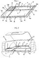
- Figure 2 shows the application of the holder device according to figure 6 onto the floor P of the rear luggage compartment V of a sedan car A: in this case the frame 3 is directly integrated with the compartment V, during manufacturing of the car.
- the rods 1, 2 fitted onto the frame 3 are oriented one parallelly to and the other transversely to the longitudinal axis of the car V.
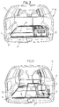
- Figures 7 and 8 show the application of the holder device according to the embodiment of figure 4, to the loading floor P of a station wagon or utility car B, having rear seats provided with foldable backrests T.
- rods 1, 2 of adjustable length are employed, having for instance a telescopic structure, so as to allow the holder device according to the invention to be used either in the raised condition of the rear backrests T (figure 7), or the lowered condition thereof (figure 8).
- the holder device according to the invention can be to advantage employed in order to improve transportation convenience and safety of objects resting on a loading floor or platform not only of cars, but also for vessels, aircrafts, railway vehicles and the like.
Landscapes
- Engineering & Computer Science (AREA)
- Transportation (AREA)
- Mechanical Engineering (AREA)
- Vehicle Step Arrangements And Article Storage (AREA)
Abstract
Holder device for a loading floor (P) of a transportation vehicle, comprising at least two rods (1, 2) intended to be arranged in a crossed configuration substantially parallelly to the loading floor (P) at a predetermined distance therefrom, and releasable locking means (4a, 5a) for rigidly securing the rods (1, 2), at the respective ends thereof (1a, 1b; 2a, 2b), to the loading platform (P). The rods (1, 2) define receptacles (R) for containing objects carried on the loading floor (P), so as to prevent accidental displacement thereof when the vehicle is travelling.
Description
- The present invention is related to a device intended to be applied to a loading floor or platform of a vehicle for holding articles resting on such a loading floor.
- The device according to the invention is essentially characterized in that it comprises at least two rods intended to be positioned in a crossed configuration substantially parallelly to the loading floor at a predetermined distance therefrom, and disengageable locking means for rigidly securing said rods, at the respective ends thereof, to the loading floor.
- The holder device according to the invention allows, in an extremely simple, convenient and cheap way, to subdivide the area of the loading floor into receptacles containing the objects carried thereon, so as to prevent accidental and undesired displacements thereof during transportation. The dimensions, configuration and disposition of the receptacles thus defined may be readily adjusted by simply changing the relative positioning between the two rods, so as to match with those of the transported loads.
- The device thus performs an effective safety task and can easily suit loading floors or platforms of different sizes by employing rods of different length, or even of adjustable length, for instance by means of a telescopic structure thereof.
- When the holder device need not to be used, the two rods may be readily released and stored anywhere, even on board the vehicle, with a negligible encumbrance.
- The holder device of the invention may be applied as an "after market" fitting to already existing vehicles, or may be directly provided by the vehicle manufacturer as an original equipment. The device can be conveniently employed with any transportation land vehicles (cars, trucks, railway vehicles), as well as with waterborne vessels and aircrafts.
- The disengageable locking means for fixing the rod ends to the loading floor of the vehicle may be conveniently designed so as to enable positioning of these rods according to different configurations of mutual crossing. These locking means may include for each rod, according to a preferred embodiment of the invention, a pair of support members adapted to be applied onto the loading floor of the vehicle generally perpendicularly to the rod and provided with respective quick anchoring elements for the ends thereof.
- These quick anchoring elements may be conveniently constituted by a plurality of side-by-side snap-in seats.
- The support members may for instance be comprised of modular bars, secured onto the vehicle loading floor either detachably or permanently.
- The support bars may be further separated from one another, and produced by cutting a set length of a continuous piece long enough to cover the maximum size contemplated for the loading floors of a set type of vehicles, or they may be interconnected at the respective adjacent ends thereof so as to define a monolithic frame substantially shaped like the perimeter of the loading floor of a specific vehicle.
- Further features and advantages of the invention will become apparent from the following detailed description, with reference to the accompanying drawings purely provided by way of non-limiting example, in which:
- figure 1 is a diagrammatic perspective view of a preferred embodiment of the holder device according to the invention,
- figure 2 shows the application of the holder device to the rear luggage compartment of a sedan car,
- figures 3 through 6 are diagrammatic top plan views showing four different embodiments of the holder device, and
- figures 7 and 8 are perspective views showing the application of the holder device to the loading floor of a station wagon car in two different configurations thereof.
- In the embodiment shown in figure 1, the holder device according to the invention essentially comprises two
rods support frame 3, intended to be placed on the loading floor or platform P of a transportation vehicle, for instance of a car. - The
support frame 3 has a generally quadrangular shape and is constituted by a pair ofbar elements 4 oriented parallelly to therod 2 and supporting the ends 1a, 1b of therod 1, and by a pair ofbar elements 5 oriented parallelly to therod 1 and supporting the ends 2a, 2b of therod 2. - In the example of figure 1, the
support bars 5 have a slightly greater height than thesupport bars 4, which allows the tworods - For retaining the ends 1a, 1b and 2a, 2b of the
rods respective support bars bars rods rods rods bar dotted lines - The spaces delimited between the
rods support bars rods - It is evident that using only two
rods - As previously explained, in the case of the example shown in figure 1 the two pairs of
support bars frame 3 in one piece, which can be prefabricated according to the shape or, to better say, to the outer perimeter of the loading floor P for which the holder device is intended to be used. - In alternative, the two pairs of
support bars support bars - According to another embodiment, the
support bars rods - Figure 5 shows an embodiment according to which the support bars of the holder device are designed so as to copy as precisely as possible the perimeter of a loading floor P having curved areas S (for instance corresponding to the wheelhouses of a car), anyhow employing straight profiles for the support rods. In this case the two
bars 5 have a broken-line configuration, defined for each one by twoportions support bars 4 by means of respective joiningmembers 6. - The example of figure 6 shows an application for the same loading floor P of figure 5, according to which the two pairs of
support bars support bars 5 are formed with respectivecurved portions 5d shaped as the curved areas S of the loading floor P. - Figure 2 shows the application of the holder device according to figure 6 onto the floor P of the rear luggage compartment V of a sedan car A: in this case the
frame 3 is directly integrated with the compartment V, during manufacturing of the car. As it can be seen, therods frame 3 are oriented one parallelly to and the other transversely to the longitudinal axis of the car V. - Figures 7 and 8 show the application of the holder device according to the embodiment of figure 4, to the loading floor P of a station wagon or utility car B, having rear seats provided with foldable backrests T. In this
case rods front support bar 4 more forwardly, to usebars 5 of a greater length (or to add extension members thereto), and to increase correspondingly the length of therods - In the case of figure 8 the use of two pairs of
rods 1 is also depicted, which enable providing a plurality or receptacles R for holding different objects, among which for instance a supplementary seat Z. - As pointed out in the above, the holder device according to the invention can be to advantage employed in order to improve transportation convenience and safety of objects resting on a loading floor or platform not only of cars, but also for vessels, aircrafts, railway vehicles and the like.
- Naturally the details of construction and the embodiments may be widely varied with respect to what has been disclosed and illustrated, without thereby departing from the scope of the present invention, such as defined in the appended claims.
Claims (13)
- Holder device for a vehicle loading floor (P), characterized in that it comprises at least two rods (1, 2) intended to be positioned in a crossed configuration substantially parallelly to the loading floor (P) at a predetermined distance therefrom, and disengageable locking means (4a, 5a) for rigidly securing said rods (1, 2), at the respective ends thereof (1a, 1b; 2a, 2b), to the loading floor (P).
- Holder device according to claim 1, characterized in that the locking means (4a, 5a) are adapted to allow positioning of said rods (1, 2) according to different configurations of mutual crossing.
- Holder device according to claim 1 or claim 2, characterized in that the locking means include, for each rod (1, 2), a pair of support members (4, 5) adapted to be applied onto the loading floor (P) generally perpendicularly to the rod (1, 2) and provided with respective quick anchoring elements (4a, 5a) for the ends (1a, 1b; 2a, 2b) thereof.
- Holder device according to claim 3, characterized in that said quick anchoring elements are constituted by a plurality of side-by-side snap in seats (4a, 5a).
- Holder device according to claim 4, characterized in that the anchoring elements (4a) of a pair of said support members (4) are adapted to be positioned at a distance from the loading floor (P) different from that of the anchoring elements (5a) of the other pair of said support members (5).
- Holder device according to any of claims 3 through 5, characterized in that the support members are constituted by modular bars (4, 5).
- Holder device according to claim 6, characterized in that the support bars (4, 5) are adapted to be detachably secured onto the loading floor (P).
- Holder device according to claim 6, characterized in that the support bars (4, 5) are adapted to be permanently secured onto the loading floor (P).
- Holder device according to claim 6, characterized in that the support bars (4, 5) are separated from one another.
- Holder device according to claim 6, characterized in that the support bars (4, 5) are interconnected at the respective adjacent ends thereof so as to define a monolithic frame (3) substantially shaped like the perimeter of the loading floor (P).
- Holder device according to claim 10, characterized in that said frame (3) is integrated with the loading floor (P) of the vehicle.
- Holder device according to any of the preceding claims, characterized in that the rods (1, 2) are adjustable in length.
- A transportation vehicle having a loading floor (P) provided with a holder device (1,2,4,5) according to any of the preceding claims.
Priority Applications (1)
| Application Number | Priority Date | Filing Date | Title |
|---|---|---|---|
| EP94107356A EP0681942A1 (en) | 1994-05-11 | 1994-05-11 | Holder device for a vehicle loading floor |
Applications Claiming Priority (1)
| Application Number | Priority Date | Filing Date | Title |
|---|---|---|---|
| EP94107356A EP0681942A1 (en) | 1994-05-11 | 1994-05-11 | Holder device for a vehicle loading floor |
Publications (1)
| Publication Number | Publication Date |
|---|---|
| EP0681942A1 true EP0681942A1 (en) | 1995-11-15 |
Family
ID=8215937
Family Applications (1)
| Application Number | Title | Priority Date | Filing Date |
|---|---|---|---|
| EP94107356A Withdrawn EP0681942A1 (en) | 1994-05-11 | 1994-05-11 | Holder device for a vehicle loading floor |
Country Status (1)
| Country | Link |
|---|---|
| EP (1) | EP0681942A1 (en) |
Cited By (2)
| Publication number | Priority date | Publication date | Assignee | Title |
|---|---|---|---|---|
| EP0939005A1 (en) * | 1998-01-28 | 1999-09-01 | HS Products AG Systemtechnik und Produktmanagement | Device for the fixing of articles in the luggage compartment of a motor vehicle |
| DE102019208757B4 (en) | 2019-06-17 | 2024-01-25 | Audi Ag | Arrangement for a cargo space |
Citations (3)
| Publication number | Priority date | Publication date | Assignee | Title |
|---|---|---|---|---|
| DE2018094A1 (en) * | 1970-04-15 | 1971-11-04 | Rahm, Günther, 6078 Neu-Isenburg | Room divider for automobile trunk |
| DE2701786A1 (en) * | 1977-01-18 | 1978-07-20 | Bosch Gmbh Robert | Space divider for motor car boot - has interlocking partition sections with end spacers bearing against walls of boot |
| DE7828641U1 (en) * | 1978-09-26 | 1979-04-26 | Kratzmeier, Ewald, 8060 Dachau | Device for holding objects on the loading surfaces of motor vehicles |
-
1994
- 1994-05-11 EP EP94107356A patent/EP0681942A1/en not_active Withdrawn
Patent Citations (3)
| Publication number | Priority date | Publication date | Assignee | Title |
|---|---|---|---|---|
| DE2018094A1 (en) * | 1970-04-15 | 1971-11-04 | Rahm, Günther, 6078 Neu-Isenburg | Room divider for automobile trunk |
| DE2701786A1 (en) * | 1977-01-18 | 1978-07-20 | Bosch Gmbh Robert | Space divider for motor car boot - has interlocking partition sections with end spacers bearing against walls of boot |
| DE7828641U1 (en) * | 1978-09-26 | 1979-04-26 | Kratzmeier, Ewald, 8060 Dachau | Device for holding objects on the loading surfaces of motor vehicles |
Cited By (2)
| Publication number | Priority date | Publication date | Assignee | Title |
|---|---|---|---|---|
| EP0939005A1 (en) * | 1998-01-28 | 1999-09-01 | HS Products AG Systemtechnik und Produktmanagement | Device for the fixing of articles in the luggage compartment of a motor vehicle |
| DE102019208757B4 (en) | 2019-06-17 | 2024-01-25 | Audi Ag | Arrangement for a cargo space |
Similar Documents
| Publication | Publication Date | Title |
|---|---|---|
| US6457765B1 (en) | Vehicle seat arrangement | |
| US5492386A (en) | Flexible seating arrangement for a mini van | |
| US11767119B2 (en) | Seat system having a canted leg assembly | |
| CN103909844B (en) | Multi-purpose vehicle | |
| GB2096232A (en) | A locking device for a cargo handling system | |
| US7966950B2 (en) | Vehicle rear seat shelf | |
| US5265828A (en) | Child safety seat adaptable to aircraft seat attach points | |
| JPH07505592A (en) | car seat track | |
| US6425619B2 (en) | Vehicle seat assembly | |
| FR2692861A1 (en) | Cabin of a motor vehicle equipped with partitioning means. | |
| US5961262A (en) | Cargo securing arrangement in a motor vehicle cargo space | |
| US10946775B2 (en) | Vehicle seat storage system | |
| EP1305184B1 (en) | A combination of chair and bed | |
| DE4216925C2 (en) | Device for releasably holding objects on a vehicle seat | |
| EP0681942A1 (en) | Holder device for a vehicle loading floor | |
| US4127907A (en) | Support frames adapted for use with car seats and beds | |
| EP2095998B1 (en) | Cargo mat | |
| US20040100113A1 (en) | Vehicle, especially a multipurpose vehicle | |
| CA2325202A1 (en) | Support apparatus | |
| US5120017A (en) | Vehicle seat adapter | |
| US20100176620A1 (en) | Self-supporting bench assembly for personnel transport | |
| DE10044529A1 (en) | Modular system for converting standard transporters and large limousines in accordance with customer wishes comprises a foldable table installed in a holding rail between the front and rear seats | |
| CN110356565A (en) | The seat of the vehicles | |
| US4249768A (en) | Vehicles including a materials supporting surface adapted for use in underground mining operations | |
| EP1630032B1 (en) | Vehicle seat |
Legal Events
| Date | Code | Title | Description |
|---|---|---|---|
| PUAI | Public reference made under article 153(3) epc to a published international application that has entered the european phase |
Free format text: ORIGINAL CODE: 0009012 |
|
| AK | Designated contracting states |
Kind code of ref document: A1 Designated state(s): DE ES FR GB SE |
|
| 17P | Request for examination filed |
Effective date: 19960504 |
|
| 17Q | First examination report despatched |
Effective date: 19970401 |
|
| STAA | Information on the status of an ep patent application or granted ep patent |
Free format text: STATUS: THE APPLICATION IS DEEMED TO BE WITHDRAWN |
|
| 18D | Application deemed to be withdrawn |
Effective date: 19970812 |