EP0938695B1 - Vorrichtung zur umwandlung von strom in druck - Google Patents
Vorrichtung zur umwandlung von strom in druck Download PDFInfo
- Publication number
- EP0938695B1 EP0938695B1 EP19970950593 EP97950593A EP0938695B1 EP 0938695 B1 EP0938695 B1 EP 0938695B1 EP 19970950593 EP19970950593 EP 19970950593 EP 97950593 A EP97950593 A EP 97950593A EP 0938695 B1 EP0938695 B1 EP 0938695B1
- Authority
- EP
- European Patent Office
- Prior art keywords
- armature
- nozzle
- converter
- pole
- fluid
- Prior art date
- Legal status (The legal status is an assumption and is not a legal conclusion. Google has not performed a legal analysis and makes no representation as to the accuracy of the status listed.)
- Expired - Lifetime
Links
Images


Classifications
-
- G—PHYSICS
- G05—CONTROLLING; REGULATING
- G05D—SYSTEMS FOR CONTROLLING OR REGULATING NON-ELECTRIC VARIABLES
- G05D16/00—Control of fluid pressure
- G05D16/20—Control of fluid pressure characterised by the use of electric means
- G05D16/2006—Control of fluid pressure characterised by the use of electric means with direct action of electric energy on controlling means
- G05D16/2013—Control of fluid pressure characterised by the use of electric means with direct action of electric energy on controlling means using throttling means as controlling means
- G05D16/2022—Control of fluid pressure characterised by the use of electric means with direct action of electric energy on controlling means using throttling means as controlling means actuated by a proportional solenoid
-
- Y—GENERAL TAGGING OF NEW TECHNOLOGICAL DEVELOPMENTS; GENERAL TAGGING OF CROSS-SECTIONAL TECHNOLOGIES SPANNING OVER SEVERAL SECTIONS OF THE IPC; TECHNICAL SUBJECTS COVERED BY FORMER USPC CROSS-REFERENCE ART COLLECTIONS [XRACs] AND DIGESTS
- Y10—TECHNICAL SUBJECTS COVERED BY FORMER USPC
- Y10T—TECHNICAL SUBJECTS COVERED BY FORMER US CLASSIFICATION
- Y10T137/00—Fluid handling
- Y10T137/2278—Pressure modulating relays or followers
Definitions
- This invention relates generally to instruments for converting electrical current levels to fluid pressure.
- I/P motor DC current amplitude (I) to pneumatic pressure (P) converter
- electropneumatic positioner an armature of magnetizable material is suspended in a magnetic circuit closely spaced from a nozzle through which a pressurized pneumatic line is controllably vented.
- the magnetic circuit includes an electromagnetic coil assembly which produces a variable magnetic field corresponding to the amplitude of an electrical current (i.e., the electrical input signal) applied to the coil.
- an electrical current i.e., the electrical input signal
- the gap between armature and nozzle remains relatively constant, as the combination of the net magnetic force acting on the armature together with any resilience in its suspension just balances the force of the nozzle blast on the armature.
- the armature will move either closer to or farther away from the nozzle, blocking the nozzle blast either more or less, thus increasing or decreasing the pressure in the line as a function of the DC electrical current level.
- U.S. Patent No. 4,579,137 discloses an electro-pneumatic transducer having a magnetizable housing defining a chamber and comprised of a top section and a bottom section.
- the bottom section has an annular side wall and a center post with a central bore providing a nozzle communicating with fluid inlet and outlet lines outside the housing.
- Held between the top and bottom sections within the chamber is a membrane having a magnetizable button forming an armature located directly above a valve seat at the top of the nozzle.
- the center post provides one pole piece and a flat upper portion of the top section provides another pole piece, with the membrane and the magnetizable button positioned in a gap therebetween. Wrapped around the center post is a coil for actuating the button on the membrane to bring it closer to or move it away from the valve seat, and thereby adjust the flow through the nozzle and pressure at the outlet.
- British patent application 2137319A describes an electro-pneumatic transducer having a pneumatic relay in which the pressure of the air at the outlet varies in accordance with the back pressure of the air at a bleed nozzle.
- the bleed nozzle back pressure is changed by the armature of a solenoid with the armature opposing the nozzle outlet.
- the armature which is provided by a floating permanent magnet, is urged towards the nozzle outlet with a force responsive to a current flowing through a coil of the solenoid, which partially surrounds the magnet.
- a second permanent magnet positioned below the coil on an opposite side of the first magnet, rests on an adjustment screw. The axial position of the second magnet is selectively set to calibrate the transducer by adjusting the position of the first magnet under pre-selected conditions.
- an electropneumatic motor e.g., a current to pressure converter
- an electropneumatic motor includes an electrically energizable magnetic circuit with an armature resiliently suspended in the air gap defined between two opposed pole pieces one of which includes an axially adjustable member of magnetic material.
- a fluid nozzle is carried by one of the pole pieces.
- the axial adjustment of the pole piece member affects the strength of the magnetic field induced by an electric current.
- the adjustable pole piece member may include ea magnetizable portion of the core which is axially movable relative to the core.
- the armature is in the form of a slug of soft magnetically permeable material centered on a flat spring in the form of a diaphgram.
- the periphery of the diaphragm is captured between upper and lower mating cylindrical housings of magnetic material, each having an end portion supporting opposing pole pieces, one associated with the coil and the other supporting the nozzle.
- the housing is made of chrome-nickel alloy, made, for example, through metal injection molding, with the armature made of Hastelloy B.
- pole piece members are fixed.
- One pole piece member includes a permanent magnet, which is axially movable relative to the armature.
- the permanent magnet is a solid element, e.g., a strong rare earth magnet in a disk shape, centered in the face of the pole piece surrounded by an electrical coil assembly.
- an axially moveable permanent magnet on the face of the coil pole piece is used to adjust the operating point of the I/P converter.
- the armature is spring biased or prestressed so that the nozzle would be closed if the permanent magnetic were not applied.
- the permanent magnet is advanced toward the armature until it pulls the armature away from the nozzle. This adjustment allows the I/P converter's operating characteristics to be calibrated.
- an adjustable coil core member permits the force characteristic to be adjusted independently of the current in a practical manner for calibration of the instrument.
- the flapper nozzle distance can be adjusted by moving the permanent magnet axially until the correct operating point is adjusted.
- the relationship between current and force can be improved by use of a stationary or adjustable permanent magnet at the pole face. At low currents the force on the armature without a permanent magnet is low.
- the permanent magnet of the present invention the static field of the permanent magnet results in greater force being available to move the armature at low current levels, thus permitting a reduction in the size and weight of the I/P motor.
- Using a permanent magnet in the end of the pole piece facing the armature also more nearly linearizes the relationship between low current levels and the resultant force acting on the armature, and, in the disclosed implementation, makes the resulting force dependent on the current direction.
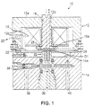
- an I/P motor includes a generally cylindrical cover or housing 10 with integral closed ends made of magnetic material, e.g., low carbon 1010-1020 steel.
- the housing consists of two mating components, a cup-shaped upper portion 12 and a lower cylindrical portion 14 with a shallow circular recess 14a.
- the top 12a of the upper portion of the housing 12 has a coaxial threaded bore 12b which receives the threaded end of a bolt-like upper pole piece 16 of the same material.
- the lower end of the pole piece 16 terminates in an enlarged coaxial disc shaped end or pole face 16a, as shown in the FIG. 1.
- a coil assembly 18 consisting of, e.g., 8000 turns of 39 gauge magnet wire on a nylon bobbin, as shown, with a two zener diodes across the coil leads (not shown).
- the bobbin is bonded to the underside of the top of the housing 12a and is not connected directly to the pole piece 16.
- Wires 20 extend out through an opening 12c in the side wall of the upper housing 12a to carry current to the coil from an external source (not shown). Current signal levels are typically in the range O to 4 mA.
- the lower portion of the housing 14 is mated to the upper housing 12 in an interlocking joint with set screws as shown which clamps the periphery of a nominally flat, diaphragm-like spring 22, for example, etched with three spiral arms 24 as shown in FIG. 2, and made of nonmagnetic 300 series stainless steel.
- An optional spacer ring 26 between the housing halves clamps the spring firmly in position just below the pole face 16a.
- the spring has a thickness of, e.g., .0075 inch.
- Attached to the center of the upper surface of the spring 22 is a magnetically permeable armature 28 in the form of a disc-shaped slug.
- the armature 28 can be made of the same steel as the housing and have thickness of about 0.0185 inch with a diameter slightly less than that of the pole face. Thus, the armature sits just below the pole face resiliently suspended by the flat spring 22.
- the lower housing 14 is part of the magnetic circuit for the electromagnetic coil and also includes a pole piece 30 carrying an integral nozzle 32 at its upper end with coaxial nozzle insert 34 (FIG. 3) of nonmagnetic 300 series stainless steel.
- the nozzle insert sticks up above the end of the nozzle 32 slightly as shown in FIG. 3 (e.g., .0005").
- the body of the lower housing 14 and nozzle pole piece 30 are channeled as shown in FIG. 1 for delivery of pressurized air to the nozzle from the supply inlet 36 via an adjustable restrictor 38 in the form of a threaded needle valve.
- the output from the I/P motor is taken from air outlet 40 which communicates with the channel supplying the nozzle.
- nozzle pole piece 30 is threadably received in the housing 14 so that the position of the nozzle above the floor of the recess 14a can be adjusted.
- the pressure in the output line is a function of the gap G1 between the nozzle insert 34 and the armature 28 as shown in FIG. 3.
- the bigger the gap the more air escapes through the nozzle and the lower the pressure at the outlet 40, and vice versa.
- the gap G1 also determines the force of the nozzle blast against the armature 28.
- upper pole face 16a has larger dimensions than the lower pole face of pole piece 30 and the lower pole face includes the projecting nozzle of non-magnetic material, the reluctance decreases in the direction of the lower pole 30 and creates an inhomogenous field.
- Increasing flux density in the air gap between the nozzle 32 and pole face 16a by increasing the current input to the coil 18 causes the armature to experience a magnetic force tending to pull armature 28 toward the nozzle, thus permitting the armature to block or choke the nozzle to a greater degree which increases the pressure between the nozzle and restrictor 38, which is in turn communicated directly to the outlet 40.
- Both lower gap G1 and upper gap G2 between the armature and the pole face 16a determine the total reluctance of the air gap between the nozzle and the pole face and thus the flux gradient experienced by the armature.
- the gaps G1 and G2 should be made as small as possible for improved gain.
- a typical gap size for G1 at zero current is .005 inch and for G2 is .001 inch.
- FIG. 4 An improvement on the I/P motor design of FIG. 1 is shown in FIG. 4.
- the I/P motor 50 of FIG. 4 comprises upper and lower cylindrical mating housing halves 52 and 54 made of the same magnetic material and opposed pole pieces 56 and 58.
- the housing part has a fixed upper pole piece 56 with a depending pole face 56a spaced from the smaller lower pole face 58a and nozzle insert 60.
- Upper pole face 56a is larger in area than lower pole face 58a.
- a bobbin wound coil 62 surrounds the upper pole piecs 56 as shown.
- a flat spring 64 clamped between the housing halves carrying a disc-shaped armature 66 of magnetic material is suspended in the gap between and parallel to the opposed upper and lower pole faces 56a and 58a.
- FIG. 4 An improvement on the I/P motor design of FIG. 1 is shown in FIG. 4.
- the armature is mounted beneath the flat spring unlike FIG. 1.
- the nozzle air flow defined by the nozzle flapper gap creates a pressure difference which controls a pneumatic constant flow preamplifier in the way that the output pressure is independent of the supply pressure.
- the pneumatic line inlet, restrictor and outlet communicating with the nozzle 60 are not shown in FIG. 4.
- the I/P motor 50 of FIG. 4 includes a small permanent magnet 70, preferably a rare earth magnet, situated in an opening 72 in the center of the upper pole face 56a on the end of a rod 74 of nonmagnetic material, which can be pressed or threaded in the upper pole piece 56 as shown in FIG. 4.
- the magnet 70 may be advanced toward or away from the armature 66 by means of the axially positionable rod.
- FIG. 1 One of the attributes of the design of FIG. 1 is that it requires extremely tight tolerances to get the correct operating point of the flapper nozzle system. In addition, at low currents there is very low resulting force on the armature due to the quadratic characteristic. As shown in FIG. 5, the dotted line represents the relationship between current and force on the armature 66. As the current approaches zero the relative change in force diminishes dramatically. In addition, as the current passes through zero and becomes more negative, the force starts back up in the positive direction because of the quadratic characteristic. In the improved embodiment of FIG.
- the permanent magnet integrated into the pole piece generates an additional magnetic field partly acting (I) between the magnet 70 and the surrounding soft iron of the upper pole piece 56 as well as partly through (2) the air gap between the upper and lower pole faces 56a and 58a.
- the resulting net magnetically produced force on the armature is chiefly due to the product of the two magnetic fields, one permanent, the other generated by the electrical current.
- the characteristic relationship between current and force on the armature becomes decidedly more linear, the force level is very much increased, especially at very low current levels and the force direction becomes dependent on the current direction, as shown in FIG. 5, in contrast to the dotted curve representing the current/force relationship without the permanent magnet.
- the force is given by: F ⁇ ⁇ 2 e with ⁇ e the magnetic flux generated by the current.
- ⁇ e ⁇ nI With the permanent magnet added: F ⁇ ( ⁇ s + ⁇ e ) 2 ⁇ ⁇ 2 s + 2 ⁇ s ⁇ e + ⁇ 2 e with ⁇ e ⁇ nI and ⁇ s ⁇ part of the magnetic flux generated by the magnet F ⁇ ⁇ 2 3 + 2 n I ⁇ s + ( n I ) 2
- the first term F ⁇ ⁇ 2 s is acting in the opposite direction of the force which attracts the plate to the upper pole piece and doesn't contribute additively in a positive manner to the operating force.
- the second term F ⁇ 2nI ⁇ s generates force linearly proportional to the current and the static field in the air gap and depends on the current direction as shown in FIG. 5.
- the third term F ⁇ (nI) 2 contributes a quadratic part to the force independent of the current direction. In practice, this linearity deviation is masked by the nozzle flapper characteristic.
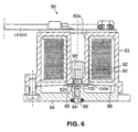
- FIG. 6 A prototype I/P motor 80 implementing the design principles of the embodiment of FIG. 4 is shown in FIG. 6.
- Upper and lower cylindrical housing portions 82 and 84 matingly clamp a flat spring 86 carrying a disc shaped armature 88 between opposing pole faces of different dimensions.
- An integral hollow central post 82a expends from the top of the upper housing 82 and carries coil assembly 90.
- the lower end of the post 82a forms the outer portion 82b of the pole face.
- An adjustable pole member 92 is pressed in or threadably received inside the post 82a. By pressing or turning the pole member 92, it can be advanced within the post 82a.
- a rare earth permanent magnet 94 is disposed in the end face of the pole member 92. Thus the axial position of the magnet 94 can be independently determined.
- nonmagnetic nozzle insert 98 is coaxially disposed in the upper end of the lower pole piece 100.
- the proportion of the field strength of the permanent magnet acting on the air gap between the upper and lower pole faces versus that between the magnet and upper pole piece can be modified by adjusting the axial position of the magnet 94.
- the flat spring 86 is prestressed so that the nozzle is closed without the force of the permanent magnet, as shown in FIG. 6,
- the upper face of the nozzle and the border of the lower housing part are on the same level.
- the thickness of the soft iron plate defines in combination with the spring strength the value of the prestressing.
- the I/P motor of FIG. 6 has several ether improvements.
- the upper and lower housing and their integral pole pieces are preferably made of chrome-nickel alloy. Chrome-nickel has substantially better magnetic properties than the steel of prior devices. Further the housing is similar to stainless steel and has very good anticorrosive properties.
- the chrome-nickel housing is made through metal injection molding in which metallic particles are suspended in a polymer and fired. This results in the metal fusing and polymer being displaced.
- the spring is manufactured from Hastelloy B.
Landscapes
- Physics & Mathematics (AREA)
- Fluid Mechanics (AREA)
- General Physics & Mathematics (AREA)
- Engineering & Computer Science (AREA)
- Automation & Control Theory (AREA)
- Supply Devices, Intensifiers, Converters, And Telemotors (AREA)
- Reciprocating, Oscillating Or Vibrating Motors (AREA)
- Electromagnets (AREA)
Claims (14)
- Strom/Druck-Wandler (50) zur Umwandlung eines Eingangs-Stromsignales in ein Ausgangs-Drucksignal, aufweisend:einen magnetischen Schaltkreis (52, 54);zwei Polstücke (56, 58) mit gegenüberliegenden Polflächen (56a, 58a) von unterschiedlichen Abmessungen, die dazwischen einen Luftspalt in dem magnetischen Schaltkreis vorgeben;einen magnetisch ansprechbaren Anker (66), der federnd in dem Luftspalt aufgehängt ist;eine Fluidleitung unter Druck mit einem Einlaß (36) und einem Auslaß (40);wobei eines der Polstücke eine Düse (60) besitzt, die sich durch seine Polfläche erstreckt, und die Düse (60) sich in direkter Fluidverbindung mit der Fluidleitung unter Druck zwischen dem Einlaß (36) und dem Auslaß (40) derselben befindet, um das Fluid in der Fluidleitung durch die Düse zu entlüften, wobei die Düse in bezug auf den Anker (66) so angeordnet ist, daß aus der Düse austretendes Fluid auf den Anker (66) auftrifft;eine elektrische Spulenanordnung (62), die eines der Polstücke umgibt, um den magnetischen Schaltkreis zu erregen und den Anker dichter an die Düse zu bewegen, um das aus der Düse austretende Fluid durch den Anker selbst mehr oder weniger zu blockieren, was zu einem begleitenden Anwachsen im Druck des Fluides am Auslaß der Fluidleitung in direkter Funktion des Pegels des in der elektrischen Spulenanordnung fließenden Stromes führt; wobeidas andere der Polstücke ebenfalls ein axial einstellbares magnetisches Element (70) in der Nähe seiner Polfläche (56a) umfaßt, und wobei das begleitende Anwachsen oder die Abnahme im Druck des Fluides am Auslaß der Fluidleitung hierdurch eine direkte Funktion des Pegels des in der Spulenanordnung (62) fließenden elektrischen Stromes ist.
- Wandler nach Anspruch 1, wobei das axial einstellbare magnetische Element (70) ein Permanentmagnet ist.
- Wandler nach Anspruch 2, wobei der Permanentmagnet in der Fläche des anderen der Polstücke (56) angeordnet ist.
- Wandler nach Anspruch 3, wobei die Spulenanordnung (62) das Polstück (56) mit dem Permanentmagneten (70) umgibt.
- Wandler nach Anspruch 4, wobei ein Magnethalter (74), der den Magneten (70) trägt, einstellbar in dem Polstück (56) aufgenommen wird.
- Wandler nach Anspruch 1, wobei der magnetische Schaltkreis (52, 54) durch ein Gehäuse vorgegeben ist, das aus einer Chrom/Nickel-Legierung hergestellt ist.
- Wandler nach Anspruch 6, ferner umfassend eine Flachfeder (64), die den in dem Gehäuse angeordneten Anker (66) trägt, wobei die Feder aus einem Material hergestellt ist, dessen thermischer Expansionskoeffizient an das Material des Gehäuses angepaßt ist.
- Wandler nach Anspruch 6, wobei die Feder (64) aus Hastelloy B. hergestellt ist.
- Elektropneumatischer Wandler nach Anspruch 3, ferner umfassend:eine federnde Aufhängung (64) für den Anker, die permanent genügend vorgespannt ist, um den Anker so dicht wie möglich an die Düse (60) zu zwingen und einen Spalt in der Spulenanordnung (62) vorzugeben.
- Wandler nach Anspruch 1, ferner umfassend Mittel zur Einstellung der effektiven axialen Position des einstellbaren magnetischen Elementes (70), um den Abstand zwischen dem magnetischen Element und dem Anker (66) zu variieren und einen Betriebspunkt des Wandlers festzulegen.
- Wandler nach Anspruch 10, wobei das einstellbare magnetische Element (70) ein Permanentmagnet ist, der axial einstellbar in der Fläche (56a) des Polstückes angeordnet ist.
- Verfahren zur Kalibrierung des Arbeitspunktes eines Strom/Druck-Wandlers zur Umwandlung eines Eingangs-Stromsignales in ein Ausgangs-Drucksignal, wobei der Wandler besitzt einen magnetischen Schaltkreis (52, 54), der durch einen elektrischen Strom erregt wird, einen magnetisch ansprechenden Anker (66), der federnd in dem Luftspalt zwischen zwei Polflächen unterschiedlicher Abmessungen in dem Schaltkreis aufgehängt ist, eine Fluiddüse (60) in einer der Polflächen (58a), die Fluid unter Druck zu dem Anker richtet, um eine Fluid-Versorgungsleitung zu entlüften, deren Ausgangs-Druckpegel eine direkte Funktion des Strompegels ist, wobei das Verfahren umfaßt:die Hinzufügung eines beweglichen Permanentmagneten (70) zu der anderen Polfläche (56a);die permanente Vorbelastung der Aufhängung für den Anker (66), so daß sich der Anker anfänglich so dicht wie möglich an der Düse (60) befindet und hierdurch die Düse blockiert;ein Vorschieben des Permanentmagneten (70) bis der Anker (66) zunächst von der Düse (60) weggezogen ist, um einen Betriebspunkt des Wandlers festzulegen.
- Strom/Druck-Wandler zur Umwandlung eines Eingangs-Stromsignales in ein Ausgangs-Drucksignal, aufweisend:eine Gehäuseanordnung (52, 54), die einen magnetischen Schaltkreis vorgibt, der zwei Polstücke (56, 58) mit axial gegenüberliegenden Polflächen (56a, 58a) von unterschiedlichen effektiven Abmessungen einschließt, die dazwischen einen Luftspalt in dem magnetischen Schaltkreis mit einem Fluß-Dichtegradienten definieren;eine federnde Membrananordnung, die an ihrem Umfang durch die Gehäuseanordnung abgestützt und in dem Spalt aufgehängt ist, wobei die Membrananordnung einen weichmagnetischen Anker (66) direkt zwischen den Polflächen trägt;eine Fluidleitung unter Druck, die einen Einlaß (36) und einen Auslaß (40) besitzt;wobei das Polstück mit der Fläche (58a) mit geringerer effektiver Abmessung eine Düse (60) besitzt, die sich durch die Polfläche (58a) in Richtung des Ankers in direkter Fluidverbindung mit der Fluidleitung unter Druck zwischen dem Einlaß (36) und dem Auslaß (40) derselben erstreckt, um das Fluid in der Fluidleitung durch die Düse (60) zu entlüften, wobei die Düse (60) relativ zu dem Anker (66) angeordnet ist, so daß durch die Düse (60) austretendes Fluid zwangsläufig auf den Anker (66) auftrifft;eine elektrische Spulenanordnung (62), die das andere der Polstücke (56) umgibt, um den magnetischen Schaltkreis zu erregen und den Anker (66) zur Bewegung dichter an die Düse (60) zu zwingen, um das aus der Düse austretende Fluid zu blockieren, was zu einem begleitenden Anwachsen im Druck des Fluides am Auslaß der Fluidleitung führt; wobeidas begleitende Anwachsen oder die Abnahme in dem Fluiddruck am Auslaß der Fluidleitung eine direkte Funktion des Pegels des elektrischen Stromes ist, der in der Spulenanordnung (62) fließt und wobeiein Permanentmagnet (70) in der Fläche (56a) des anderen der Polstücke (56) mit der größeren effektiven Abmessung angeordnet ist, und dieser Permanentmagnet (70) nahezu die Kraft auf den Anker (66) in bezug auf einen Strom mit niedrigem Strompegel nahe einem Strom von Null im Vergleich zu dem gleichen System ohne Permanentmagnet (70) linearisiert.
- Wandler nach Anspruch 13, wobei das Vorhandensein des Permanentmagneten (70) die Richtung der Kraft auf den Anker (66) veranlaßt, unabhängig von der Polarität des Stromes zu sein.
Applications Claiming Priority (3)
| Application Number | Priority Date | Filing Date | Title |
|---|---|---|---|
| US748821 | 1985-06-26 | ||
| US74882196A | 1996-11-14 | 1996-11-14 | |
| PCT/US1997/020675 WO1998021633A2 (en) | 1996-11-14 | 1997-11-12 | Current to pressure converter |
Publications (2)
| Publication Number | Publication Date |
|---|---|
| EP0938695A2 EP0938695A2 (de) | 1999-09-01 |
| EP0938695B1 true EP0938695B1 (de) | 2003-10-08 |
Family
ID=25011076
Family Applications (1)
| Application Number | Title | Priority Date | Filing Date |
|---|---|---|---|
| EP19970950593 Expired - Lifetime EP0938695B1 (de) | 1996-11-14 | 1997-11-12 | Vorrichtung zur umwandlung von strom in druck |
Country Status (5)
| Country | Link |
|---|---|
| US (1) | US6079435A (de) |
| EP (1) | EP0938695B1 (de) |
| CN (1) | CN1109943C (de) |
| DE (1) | DE69725462T2 (de) |
| WO (1) | WO1998021633A2 (de) |
Families Citing this family (25)
| Publication number | Priority date | Publication date | Assignee | Title |
|---|---|---|---|---|
| UA67804C2 (uk) * | 1998-10-02 | 2004-07-15 | Роналд Нортедж | Клапан |
| US6237675B1 (en) * | 1999-06-14 | 2001-05-29 | Ford Global Technolgies, Inc. | Automatic temperature controlled seats |
| US6220569B1 (en) * | 2000-01-07 | 2001-04-24 | Clippard Instrument Laboratory, Inc. | Electrically controlled proportional valve |
| JP4088741B2 (ja) * | 2000-02-25 | 2008-05-21 | 株式会社デンソー | 電磁弁 |
| US6422532B1 (en) * | 2000-03-01 | 2002-07-23 | Invensys Systems, Inc. | Severe service valve positioner |
| JP2002235842A (ja) * | 2001-02-13 | 2002-08-23 | Jatco Ltd | 自動変速機用ソレノイドバルブ回路 |
| US7086049B2 (en) * | 2002-02-26 | 2006-08-01 | International Business Machines Corporation | Background code update for embedded systems |
| US7226035B2 (en) * | 2002-04-12 | 2007-06-05 | Seiko Epson Corporation | Valve device |
| DE10249161B3 (de) * | 2002-10-22 | 2004-01-29 | Robert Bosch Gmbh | Vorrichtung zur Einstellung eines Ankerhubs eines Magnetventils |
| US6722628B1 (en) * | 2003-02-06 | 2004-04-20 | Sturman Industries, Inc. | Miniature poppet valve assembly |
| JP4275463B2 (ja) * | 2003-06-04 | 2009-06-10 | 藤倉ゴム工業株式会社 | 電空変換式空気レギュレータ |
| AU2004280611A1 (en) * | 2003-10-09 | 2005-04-21 | Emerson Electric Co. | Valve assembly |
| US20060284131A1 (en) * | 2005-05-20 | 2006-12-21 | Parker-Hannifin Corporation | Solenoid valve |
| US7726630B2 (en) * | 2005-05-20 | 2010-06-01 | Parker-Hannifin Corporation | Solenoid valve |
| US7748683B1 (en) * | 2007-02-23 | 2010-07-06 | Kelly Edmund F | Electrically controlled proportional valve |
| US8408230B2 (en) | 2007-03-16 | 2013-04-02 | Norgren Limited | Temperature compensated I/P converter |
| US8047503B2 (en) * | 2008-02-26 | 2011-11-01 | Eaton Corporation | Conical spring bushing |
| US8128060B2 (en) * | 2009-03-25 | 2012-03-06 | Valve Tech, Inc. | Non-sliding solenoid valve |
| CN102439528B (zh) * | 2009-05-07 | 2014-10-22 | 帕克-汉尼芬公司 | 自对准轴向约束调节器阀组件 |
| US20130248612A1 (en) * | 2012-03-26 | 2013-09-26 | Caterpillar Inc. | Solenoid Actuator And Fuel Injector Using Same |
| US9739393B2 (en) | 2014-02-05 | 2017-08-22 | Pentair Flow Control Ag | Valve controller with flapper nozzle pilot valve |
| JP6628968B2 (ja) * | 2015-02-10 | 2020-01-15 | 特許機器株式会社 | 流体サーボバルブ及び流体サーボ装置 |
| EP3259510B1 (de) | 2015-02-17 | 2020-01-15 | Enfield Technologies, Inc. | Solenoidvorrichtung |
| EP3715687B1 (de) * | 2019-03-29 | 2021-10-13 | Hamilton Sundstrand Corporation | Servoventile |
| CN113268095B (zh) * | 2021-05-13 | 2022-11-01 | 潍坊工程职业学院 | 一种空气压力控制式电流控制器 |
Family Cites Families (16)
| Publication number | Priority date | Publication date | Assignee | Title |
|---|---|---|---|---|
| US3645293A (en) * | 1970-04-02 | 1972-02-29 | Johnson Service Co | Electric to fluidic transducer |
| US4579137A (en) * | 1981-10-06 | 1986-04-01 | Inotek, Inc. | Electro-pneumatic current to pressure transducer and pneumatic and electronic control circuits therefor |
| US4875499A (en) * | 1981-10-16 | 1989-10-24 | Borg-Warner Corporation | Proportional solenoid valve |
| US4540453A (en) * | 1982-10-28 | 1985-09-10 | At&T Technologies | Magnetically soft ferritic Fe-Cr-Ni alloys |
| US4532951A (en) * | 1983-03-28 | 1985-08-06 | Barber-Colman Company | Transducer utilizing electrical and pneumatic signals |
| US4610428A (en) * | 1985-03-11 | 1986-09-09 | Borg-Warner Automotive, Inc. | Hermetically sealed electromagnetic solenoid valve |
| US4835503A (en) * | 1986-03-20 | 1989-05-30 | South Bend Controls, Inc. | Linear proportional solenoid |
| US4767097A (en) * | 1987-03-27 | 1988-08-30 | William F. Everett | Stacked servoid assembly |
| US4967781A (en) * | 1989-04-05 | 1990-11-06 | Borg-Warner Automotive Electronic & Mechanical Systems Corporation | Proportional solenoid valve |
| US4954799A (en) * | 1989-06-02 | 1990-09-04 | Puritan-Bennett Corporation | Proportional electropneumatic solenoid-controlled valve |
| US5065979A (en) * | 1990-01-10 | 1991-11-19 | Lectron Products, Inc. | Constant current vacuum regulator |
| US5202658A (en) * | 1991-03-01 | 1993-04-13 | South Bend Controls, Inc. | Linear proportional solenoid |
| US5282489A (en) * | 1992-05-01 | 1994-02-01 | Valtek, Inc. | Fluid pressure modulator |
| FR2706569B1 (fr) * | 1993-06-16 | 1995-09-29 | Sagem Allumage | Electrovanne à noyau métallique tubulaire. |
| JPH0762483A (ja) * | 1993-08-30 | 1995-03-07 | Nisshin Steel Co Ltd | 軟磁性合金の溶製方法 |
| JP3476022B2 (ja) * | 1993-10-15 | 2003-12-10 | 横河電機株式会社 | 電気/空気圧変換器 |
-
1997
- 1997-11-12 WO PCT/US1997/020675 patent/WO1998021633A2/en active IP Right Grant
- 1997-11-12 DE DE1997625462 patent/DE69725462T2/de not_active Expired - Lifetime
- 1997-11-12 EP EP19970950593 patent/EP0938695B1/de not_active Expired - Lifetime
- 1997-11-12 CN CN97181361A patent/CN1109943C/zh not_active Expired - Fee Related
-
1998
- 1998-07-28 US US09/206,417 patent/US6079435A/en not_active Expired - Lifetime
Also Published As
| Publication number | Publication date |
|---|---|
| EP0938695A2 (de) | 1999-09-01 |
| WO1998021633A2 (en) | 1998-05-22 |
| WO1998021633A3 (en) | 1998-08-20 |
| US6079435A (en) | 2000-06-27 |
| DE69725462T2 (de) | 2004-08-19 |
| CN1245568A (zh) | 2000-02-23 |
| CN1109943C (zh) | 2003-05-28 |
| DE69725462D1 (de) | 2003-11-13 |
Similar Documents
| Publication | Publication Date | Title |
|---|---|---|
| EP0938695B1 (de) | Vorrichtung zur umwandlung von strom in druck | |
| US5785298A (en) | Proportional solenoid-controlled fluid valve assembly | |
| US4579137A (en) | Electro-pneumatic current to pressure transducer and pneumatic and electronic control circuits therefor | |
| US4463332A (en) | Adjustable, rectilinear motion proportional solenoid | |
| US4954799A (en) | Proportional electropneumatic solenoid-controlled valve | |
| US5407174A (en) | Proportional electropneumatic solenoid-controlled valve | |
| US5727769A (en) | Solenoid valve for flow rate control | |
| US5020771A (en) | Proportional control valve | |
| US4729398A (en) | Current-to-pressure transducers | |
| US3433256A (en) | Electrohydraulic valve | |
| JPS59183101A (ja) | 変換器 | |
| JPS60157576A (ja) | 電気制御圧力変換弁 | |
| US4638830A (en) | High sensitivity magnetic actuator | |
| JP2510667B2 (ja) | 電空式位置調整装置 | |
| US5590677A (en) | Electropneumatic positioner | |
| US3476128A (en) | Pulsed solenoid force balance device | |
| US20050145812A1 (en) | Solenoid valve and poppet assembly | |
| US4793372A (en) | Electronic vacuum regulator (EVR) with bi-metallic armature disk temperature compensator | |
| JPH0219845Y2 (de) | ||
| US4759528A (en) | Valve actuator | |
| EP0360166A2 (de) | Elektromagnetischer Kraftsensor | |
| GB2253721A (en) | Pressure control valve | |
| EP0409664B1 (de) | Druckregler und Ventilbetätigungsvorrichtung | |
| US4874005A (en) | Current to pressure tranducer employing magnetic fluid | |
| US4850384A (en) | Electric vacuum regulator |
Legal Events
| Date | Code | Title | Description |
|---|---|---|---|
| PUAI | Public reference made under article 153(3) epc to a published international application that has entered the european phase |
Free format text: ORIGINAL CODE: 0009012 |
|
| 17P | Request for examination filed |
Effective date: 19990521 |
|
| AK | Designated contracting states |
Kind code of ref document: A2 Designated state(s): DE FR GB |
|
| GRAG | Despatch of communication of intention to grant |
Free format text: ORIGINAL CODE: EPIDOS AGRA |
|
| 17Q | First examination report despatched |
Effective date: 20010219 |
|
| GRAG | Despatch of communication of intention to grant |
Free format text: ORIGINAL CODE: EPIDOS AGRA |
|
| GRAH | Despatch of communication of intention to grant a patent |
Free format text: ORIGINAL CODE: EPIDOS IGRA |
|
| GRAH | Despatch of communication of intention to grant a patent |
Free format text: ORIGINAL CODE: EPIDOS IGRA |
|
| GRAA | (expected) grant |
Free format text: ORIGINAL CODE: 0009210 |
|
| AK | Designated contracting states |
Kind code of ref document: B1 Designated state(s): DE FR GB |
|
| REG | Reference to a national code |
Ref country code: GB Ref legal event code: FG4D |
|
| REF | Corresponds to: |
Ref document number: 69725462 Country of ref document: DE Date of ref document: 20031113 Kind code of ref document: P |
|
| ET | Fr: translation filed | ||
| PLBE | No opposition filed within time limit |
Free format text: ORIGINAL CODE: 0009261 |
|
| STAA | Information on the status of an ep patent application or granted ep patent |
Free format text: STATUS: NO OPPOSITION FILED WITHIN TIME LIMIT |
|
| 26N | No opposition filed |
Effective date: 20040709 |
|
| REG | Reference to a national code |
Ref country code: DE Ref legal event code: R082 Ref document number: 69725462 Country of ref document: DE Representative=s name: MEHLER ACHLER PATENTANWAELTE PARTNERSCHAFT MBB, DE Ref country code: DE Ref legal event code: R082 Ref document number: 69725462 Country of ref document: DE Representative=s name: MEHLER ACHLER PATENTANWAELTE, DE |
|
| PGFP | Annual fee paid to national office [announced via postgrant information from national office to epo] |
Ref country code: FR Payment date: 20141110 Year of fee payment: 18 Ref country code: DE Payment date: 20141105 Year of fee payment: 18 Ref country code: GB Payment date: 20141112 Year of fee payment: 18 |
|
| REG | Reference to a national code |
Ref country code: DE Ref legal event code: R119 Ref document number: 69725462 Country of ref document: DE |
|
| GBPC | Gb: european patent ceased through non-payment of renewal fee |
Effective date: 20151112 |
|
| REG | Reference to a national code |
Ref country code: FR Ref legal event code: ST Effective date: 20160729 |
|
| PG25 | Lapsed in a contracting state [announced via postgrant information from national office to epo] |
Ref country code: GB Free format text: LAPSE BECAUSE OF NON-PAYMENT OF DUE FEES Effective date: 20151112 Ref country code: DE Free format text: LAPSE BECAUSE OF NON-PAYMENT OF DUE FEES Effective date: 20160601 |
|
| PG25 | Lapsed in a contracting state [announced via postgrant information from national office to epo] |
Ref country code: FR Free format text: LAPSE BECAUSE OF NON-PAYMENT OF DUE FEES Effective date: 20151130 |