EP0938163B1 - Kabelendverzweiger für die Telekommunikations- und Datentechnik - Google Patents
Kabelendverzweiger für die Telekommunikations- und Datentechnik Download PDFInfo
- Publication number
- EP0938163B1 EP0938163B1 EP99101294A EP99101294A EP0938163B1 EP 0938163 B1 EP0938163 B1 EP 0938163B1 EP 99101294 A EP99101294 A EP 99101294A EP 99101294 A EP99101294 A EP 99101294A EP 0938163 B1 EP0938163 B1 EP 0938163B1
- Authority
- EP
- European Patent Office
- Prior art keywords
- housing
- cover
- cable
- base plate
- webs
- Prior art date
- Legal status (The legal status is an assumption and is not a legal conclusion. Google has not performed a legal analysis and makes no representation as to the accuracy of the status listed.)
- Expired - Lifetime
Links
Images



Classifications
-
- H—ELECTRICITY
- H01—ELECTRIC ELEMENTS
- H01R—ELECTRICALLY-CONDUCTIVE CONNECTIONS; STRUCTURAL ASSOCIATIONS OF A PLURALITY OF MUTUALLY-INSULATED ELECTRICAL CONNECTING ELEMENTS; COUPLING DEVICES; CURRENT COLLECTORS
- H01R25/00—Coupling parts adapted for simultaneous co-operation with two or more identical counterparts, e.g. for distributing energy to two or more circuits
- H01R25/003—Coupling parts adapted for simultaneous co-operation with two or more identical counterparts, e.g. for distributing energy to two or more circuits the coupling part being secured only to wires or cables
-
- H—ELECTRICITY
- H01—ELECTRIC ELEMENTS
- H01R—ELECTRICALLY-CONDUCTIVE CONNECTIONS; STRUCTURAL ASSOCIATIONS OF A PLURALITY OF MUTUALLY-INSULATED ELECTRICAL CONNECTING ELEMENTS; COUPLING DEVICES; CURRENT COLLECTORS
- H01R13/00—Details of coupling devices of the kinds covered by groups H01R12/70 or H01R24/00 - H01R33/00
- H01R13/62—Means for facilitating engagement or disengagement of coupling parts or for holding them in engagement
- H01R13/639—Additional means for holding or locking coupling parts together, after engagement, e.g. separate keylock, retainer strap
- H01R13/6392—Additional means for holding or locking coupling parts together, after engagement, e.g. separate keylock, retainer strap for extension cord
-
- H—ELECTRICITY
- H04—ELECTRIC COMMUNICATION TECHNIQUE
- H04Q—SELECTING
- H04Q1/00—Details of selecting apparatus or arrangements
- H04Q1/02—Constructional details
- H04Q1/028—Subscriber network interface devices
-
- H—ELECTRICITY
- H01—ELECTRIC ELEMENTS
- H01R—ELECTRICALLY-CONDUCTIVE CONNECTIONS; STRUCTURAL ASSOCIATIONS OF A PLURALITY OF MUTUALLY-INSULATED ELECTRICAL CONNECTING ELEMENTS; COUPLING DEVICES; CURRENT COLLECTORS
- H01R4/00—Electrically-conductive connections between two or more conductive members in direct contact, i.e. touching one another; Means for effecting or maintaining such contact; Electrically-conductive connections having two or more spaced connecting locations for conductors and using contact members penetrating insulation
- H01R4/24—Connections using contact members penetrating or cutting insulation or cable strands
- H01R4/2416—Connections using contact members penetrating or cutting insulation or cable strands the contact members having insulation-cutting edges, e.g. of tuning fork type
-
- H—ELECTRICITY
- H04—ELECTRIC COMMUNICATION TECHNIQUE
- H04Q—SELECTING
- H04Q1/00—Details of selecting apparatus or arrangements
- H04Q1/02—Constructional details
- H04Q1/14—Distribution frames
Definitions
- the invention relates to a cable terminal distributor for the telecommunication and data technology according to the preamble of claim 1.
- This distributor device consists of a terminal block and a holding part, wherein the terminal block for connecting the outgoing Subscriber lines and the holding part for connecting the system lines is provided.
- the outgoing subscriber lines are here from the operating page freely accessible to the connection elements and connected.
- the system leads are led into the holding part from below and inside of the holding part contacted to fixing parts. Only when composing the terminal block with the holding part are the subscriber lines with the System lines connected, because the connection elements and point at the other End of insulation displacement contacts, which engage in the fixing parts.
- a disadvantage of this distribution device is that the system lines in Inside the distribution device are connected and only by pulling apart the housing parts are accessible.
- the invention is based on the object, the previously known Lucasendverzweiger with a view to securing the insulation displacement contact elements the two terminal strips against unauthorized access improve.
- the invention provides according to claim 1, that in the housing means for Secure the system cables to the inner rows of insulation displacement contact elements the two terminal blocks are connected, against unauthorized To protect access. According to the invention are thus still inside of the housing, even after the removal of the housing cover, means for Secure only the system cables against unauthorized access, the system cables being connected to the inner rows of insulation displacement contact elements the two connection strips are connected.
- the public Operator of a telecommunications and data network to the inner Rows of insulation displacement contact elements of the two terminal strips Separate a system cable connected to a cable junction box secure without the private user of the telecommunications and data facilities on the system cables.
- a cable channel forming partitions and arranged near the outside of both partitions per a terminal block and the cable channel is provided with a lockable cover whose Longitudinal edges between the partitions of the cable channel and the terminal strips engage such that the adjacent insulation displacement contact elements for the system cables are secured against unauthorized access.
- the Cover two U-shaped angled longitudinal edges, whose outer webs in the plastic bodies of the Terminal strips formed clamping slots for the Cover insulation displacement contact elements. Further points the cover has several receiving openings for in close the outsides of the partitions on the base plate arranged supports engaging locking cams on.
- the cable channels at both ends pluggable cable entry plates with cutouts for Cable on. Also, the cable channels at one end Extensions of the partitions and at the other end socket-like receptacles for inserting the extensions a second housing, whereby a housing connected System of several cable distribution boxes is created.
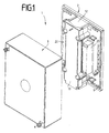
- the Jardinendverzweiger for the telecommunications and Data technology comprises a housing 1 of a base plate 2 and a box-shaped housing cover 3, the by means of two diagonally opposite corner points arranged closure elements 4, which in openings 9 in diametrically opposite corners of the base plate 2 engage, sealed with the base plate 2 connectable is.
- On the inside of the base plate 2 are two parallel partitions 5, 6 integral with the Base plate 2 made of plastic, which is between form a cable channel 7.
- the partitions 5, 6 are on their tops with perpendicular to the base plate 2 directed short slots 8 for implementation formed by system cables, not shown.
- the Cable channel 7 is at both ends with in the partitions 5, 6 formed U-shaped guides 10, 11th Guided plates 12, 13 provided for cable passage, with the openings 28 and 30 for the not system cables are provided.
- the cable channel 7 has at its one, with the plate thirteenth provided end extension webs 14 of the partitions 5, 6 and at the other, with the other plate 12 provided end a female receptacle 15 to Inserting the extension webs 14 of a second Housing 1, as explained in more detail later will be.
- the cable channel 7 is on its upper side by means a cover 19 shown lifted off in Fig. 2 made of plastic, which closes on their outsides each molded near the front ends Receiving openings 20 with passage openings for the locking cam 18 has.
- the frontal Ends of the cover 19 are with recesses 21, which is locked with latched cover 19 with the plates 12, 13 for the cable entry interact.
- both partitions 5, 6 are on the base plate 2 of the housing 1 per a terminal block 22, 23 mounted, which also serve as disconnectors can be trained.
- the terminal strips 22, 23 in a known manner in two parallel rows 26, 27 arranged in clamping slots, not shown Insulation displacement contact elements for connecting not shown system and subscriber cables, the system cables on the inner rows 26 of the Insulation displacement contact elements of the terminal strips 22, 23 are connected near the partitions 5, 6.
- the Longitudinal edges 24 of the cover 19 engage between the Partitions 5, 6 of the cable channel 7 and the terminal strips 22, 23 such that the adjacent Cutting clamp contact elements for system cables through the longitudinal edges 24 as means for securing the System cables are secured against unauthorized access.
- the longitudinal edges 24 are angled U-shaped, wherein the outer webs 25 in the plastic bodies the terminal strips 22, 23 trained, not shown clamping slots for the insulation displacement contact elements Cover as it is in the sectional view is shown in FIG. 4.
- the two terminal blocks 22, 23rd shown parallel to and close to the outsides the cable channel 7 forming and limiting partitions 5, 6 are mounted on the base plate 2.
- the respective inner row 26 of insulation displacement contact elements the two terminal strips 22, 23 serves for Connecting the system cables through the cable channel 7 fed through and through the slots 8 in the Partitions 5, 6 of the inner row 26 of insulation displacement contact elements the terminal strips 22, 23rd are fed.
- the cable channel 7 upwards unauthorized access locking cover 19 engages their U-shaped longitudinal edges 24 and with the belonging to these outer webs 25 between the outsides of the partitions 5, 6 and the adjacent ones Rows 26 of the insulation displacement contact elements of two terminal strips 22, 23, so that the connected here System cable inaccessible from unauthorized Access is secured.
- connection tool with which on top the terminal strips 22, 23 is pressed, wherein the system cables into the insulation displacement contact elements be pressed, no longer used, because of the between the partitions 5, 6 of the cable channel 7 and the inner row 26 of insulation displacement contact elements existing space not for inserting a part the connection tool is available.
- the cover 19 is by means of in the slots 17 of the supports 16 engaging locking cam 18 secured, the only removable with a special tool and thus before unauthorized access are secured.
- the recesses 21 the front sides of the cover 19 hold the plates 12th 13 for the cable passage in their guides 10,11.
- ground connections 34 serve as outdoor and cable earth for the Overvoltage protection.
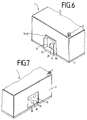
- FIG. 6 shows the one end side of the housing 1 from housing cover 3 and base plate 2 with the outstanding Extension webs 14 of the partition walls 5, 6 and the front end 21 of the cover 19, the from a U-shaped cutout 38 of the housing cover 2 are surrounded.
- the plate 12 for the cable feedthrough is an opening 28 for carrying out the System cable arranged.
- Fig. 7 shows the other one Front side of the housing 1 from the housing cover 3 and Base plate 2 with the female receptacle 15 and the other plate 13 for cable passage with through holes 30 for the system cables.
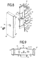
- FIGS. 8 and 9 show a housing connector 40 Plastic, consisting of a bottom plate 41 and parallel side walls 42, in the longitudinal center region in a similar manner as at the front ends of the cable channel 7 of the base plate 2 of the housing 1 one side a shot 43 and on the opposite Side parallel extension webs 44 with an underside connecting transverse nose 45th are formed.
- the other side wall portions 46 of Housing connector 40 are in the material thickness thinner or pre-stamped areas 47 provided the breakable for passing through system cables are.
- the front ends of the housing connector 40th are with extension bars 48 and a receptacle 49th provided corresponding to the extension webs 14, 44 and the recordings 15, 43 of the housing 1 and des Housing connector 40 are formed.
- the housing connector 40 is by means of a cover 50th closable.
- a support 51 with a slot 52 is provided, in which a locking cam 53 engages in a receiving opening 54 in the center of the lid 50 can be latched.
- Fig. 12 shows the arrangement of five and more Jardinendverzweigern whose housing 1 by means of several Housing connectors 40 are connected together.
- Both the base plate 2 of the housing 1 and the Base plate 41 of the housing connector 40 are with Through holes 39 and 55 for wall mounting Mistake.
Landscapes
- Engineering & Computer Science (AREA)
- Computer Networks & Wireless Communication (AREA)
- Details Of Connecting Devices For Male And Female Coupling (AREA)
- Communication Cables (AREA)
- Connections Arranged To Contact A Plurality Of Conductors (AREA)
Description
- Fig. 1
- eine perspektivische Ansicht auf die Grundplatte des Gehäuses mit dem von der Grundplatte abgehobenen kastenförmigen Gehäusedeckel,
- Fig. 2
- eine perspektivische Ansicht auf die Grundplatte des Gehäuses des Kabelendverzweigers und eine vom Kabelkanal abgehobene verriegelbare Abdeckung,
- Fig. 3
- eine teilweise aufgebrochene Draufsicht auf das Gehäuse und die Grundplatte,
- Fig. 4
- einen Querschnitt durch das Gehäuse gemäß Fig. 3,
- Fig. 5
- einen Längsschnitt durch das Gehäuse gemäß Fig. 3,
- Fig. 6
- eine perspektivische Ansicht der einen Stirnseite des Gehäuses,
- Fig. 7
- eine perspektivische Ansicht der anderen Stirnseite des Gehäuses,
- Fig. 8
- eine perspektivische Draufsicht auf einen Gehäuseverbinder und einen davon abgehobenen Deckel,
- Fig. 9
- eine Draufsicht auf den Gehäuseverbinder gemäß Fig. 8,
- Fig. 10
- eine Draufsicht auf zwei unmittelbar zusammengekoppelte Kabelendverzweiger,
- Fig. 11
- eine Draufsicht auf vier unter Zwischenschaltung eines Gehäuseverbinders sternförmig zusammengekoppelte Kabelendverzweiger und
- Fig. 12
- eine Draufsicht auf eine Mehrzahl von unter zur Hilfenahme von Gehäuseverbindern zusammengekoppelte Kabelendverzweiger.
- 1
- Gehäuse
- 2
- Grundplatte
- 3
- Gehäusedeckel
- 4
- Verschlußelement
- 5
- Tennwand
- 6
- Trennwand
- 7
- Kabelkanal
- 8
- Schlitz
- 9
- Öffnung
- 10
- Führung
- 11
- Führung
- 12
- Platte
- 13
- Platte
- 14
- Verlängerungssteg
- 15
- Aufnahme
- 16
- Stütze
- 17
- Schlitz
- 18
- Verriegelungsnocken
- 19
- Abdeckung
- 20
- Aufnahmeöffnung
- 21
- Ausnehmung
- 22
- Anschlußleiste
- 23
- Anschlußleiste
- 24
- Längsrand
- 25
- Steg
- 26
- innere Reihe von Schneid-Klemm-
- 27
- äußere Reihe / Kontaktelementen
- 28
- Öffnung
- 29
- Öffnung
- 30
- Öffnung
- 31
- Kabelführung
- 32
- Öffnung
- 33
- Öffnung
- 34
- Erdanschluß
- 35
- Querrand
- 36
- Quernut
- 37
- Durchgangsöffnung
- 38
- Freischnitt
- 39
- Durchgangsöffnung
- 40
- Gehäuseverbinder
- 41
- Bodenplatte
- 42
- Seitenwand
- 43
- Aufnahme
- 44
- Verlängerungssteg
- 45
- Quernase
- 46
- Seitenwandteil
- 47
- Fläche
- 48
- Verlängerungsteg
- 49
- Aufnahme
- 50
- Deckel
- 51
- Stütze
- 52
- Schlitz
- 53
- Verriegelungsnocken
- 54
- Aufnahmeöffnung
- 55
- Durchgangsöffnung
Claims (7)
- Kabelendverzweiger für die Telekommunikations- und Datentechnik, aus einem Gehäuse (1) mit einer Grundplatte (2) und einem Gehäusedeckel (3) sowie mit zwei auf die Grund- platte (2) montierten Anschlußleisten (22, 23) mit je 4 zwei parallelen Reihen (26) von Schneid-Klemm-Kontaktelementen zum Anschließen von System- und Teilnehmerkabeln,
dadurch gekennzeichnet, dass im Gehäuse (1) eine verriegelbare Abdeckung (19) zum Sichern der Systemkabel an die inneren Reihen (26) von Schneid-Klemm-Kontaktelementen der beiden Anschlußleisten (22, 23) vor unbefugtem Zugriff angeordnet ist. - Kabelendverzweiger nach Anspruch 1, dadurch gekennzeichnet, dass zum Sichern der Systemkabel auf der Grundplatte (2) des Gehäuses (1) zwei parallele, einen Kabelkanal (7) bildende Trennwände (5, 6) und nahe der Außenseite beider Trennwände (5, 6) je eine Anschlußleiste (22, 23) angeordnet sind und dass der Kabelkanal (7) mit der verriegelbaren Abdeckung (19) versehen ist, deren Längsränder (24) zwischen die Trennwände (5, 6) des Kabelkanals (7) und die Anschlußleisten (22, 23) derart eingreifen, dass die angrenzenden Schneid-Klemm-Kontaktelemente für die Systemkabel vor unbefugtem Zugriff gesichert sind.
- Kabelendverzweiger nach Anspruch 2, dadurch gekennzeichnet, daß die Abdeckung (19) zwei U-förmig abgewinkelte Längsränder (24) aufweist, deren äußere Stege (25) die in den Kunststoffkörpern der Anschlußleisten (22, 23) ausgebildeten Klemmschlitze für die Schneid-Klemm-Kontaktelemente abdecken.
- Kabelendverzweiger nach Anspruch 2 oder 3, dadurch gekennzeichnet, daß die Abdeckung (19) mehrere Aufnahmeöffnungen (20) für in nahe den Außenseiten der Trennwände (5, 6) angeordnete Stützen (16) eingreifende Verriegelungsnocken (18) aufweist.
- Kabelendverzweiger nach einem der Ansprüche 2 bis 4, dadurch gekennzeichnet, daß der Kabelkanal (7) an beiden Enden steckbare Platten (12, 13) mit Öffnungen (28, 30) zur Kabeldurchführung aufweisen.
- Kabelendverzweiger nach einem der Ansprüche 2 bis 5, dadurch gekennzeichnet, daß der Kabelkanal (7) an einem Ende Verlängerungsstege (14) der Trennwände (5, 6) und am anderen Ende buchsenartige Aufnahmen (15) zum Einstecken der Verlängerungs stege (14) eines zweiten Gehäuses (1) aufweisen.
- Kabelendverzweiger nach einem der Ansprüche 2 bis 6, gekennzeichnet durch einen mittels eines Deckels (50) verschließbaren Gehäuseverbinder (40) aus einer Bodenplatte (41) und parallelen Seitenwänden (42) mit Aufnahmen (43) und Verlängerungsstegen (44) sowie mit stirnseitigen Aufnahmen (49) und Verlängerungsstegen (48) zur Verbindung mehrerer Gehäuse (1) miteinander.
Applications Claiming Priority (2)
| Application Number | Priority Date | Filing Date | Title |
|---|---|---|---|
| DE19807293A DE19807293C1 (de) | 1998-02-20 | 1998-02-20 | Kabelendverzweiger für die Telekommunikations- und Datentechnik |
| DE19807293 | 1998-02-20 |
Publications (3)
| Publication Number | Publication Date |
|---|---|
| EP0938163A2 EP0938163A2 (de) | 1999-08-25 |
| EP0938163A3 EP0938163A3 (de) | 2003-03-12 |
| EP0938163B1 true EP0938163B1 (de) | 2005-04-27 |
Family
ID=7858492
Family Applications (1)
| Application Number | Title | Priority Date | Filing Date |
|---|---|---|---|
| EP99101294A Expired - Lifetime EP0938163B1 (de) | 1998-02-20 | 1999-01-25 | Kabelendverzweiger für die Telekommunikations- und Datentechnik |
Country Status (3)
| Country | Link |
|---|---|
| EP (1) | EP0938163B1 (de) |
| AT (1) | ATE294455T1 (de) |
| DE (2) | DE19807293C1 (de) |
Families Citing this family (1)
| Publication number | Priority date | Publication date | Assignee | Title |
|---|---|---|---|---|
| DE10210382C1 (de) * | 2002-03-08 | 2003-10-30 | Krone Gmbh | Zugriffsicherung für Verteilermodule |
Family Cites Families (6)
| Publication number | Priority date | Publication date | Assignee | Title |
|---|---|---|---|---|
| DE2520270C2 (de) * | 1975-05-07 | 1984-09-06 | Dr. Franz & Rutenbeck, 5885 Schalksmühle | Endverzweiger für Fernmeldekabel |
| DE3007458A1 (de) * | 1980-02-28 | 1981-09-10 | Wilhelm Quante Spezialfabrik für Apparate der Fernmeldetechnik GmbH & Co, 5600 Wuppertal | Abschlussgeraet fuer niederspannungs-kabel, insbesondere fernmeldekabel |
| CA1201195A (en) * | 1982-07-19 | 1986-02-25 | Robert A. Soltis | Bi-vertical main distributing frame connection |
| DE3348151C2 (en) * | 1983-02-23 | 1989-06-01 | Krone Ag, 1000 Berlin, De | Cable attachment device |
| DE3726741C1 (de) * | 1987-08-07 | 1988-09-01 | Krone Ag | Anschlussleiste der Fernmeldetechnik |
| US5057034A (en) * | 1989-06-28 | 1991-10-15 | Siemens Aktiengesellschaft | Distributor device for telecommunication systems |
-
1998
- 1998-02-20 DE DE19807293A patent/DE19807293C1/de not_active Expired - Fee Related
-
1999
- 1999-01-25 EP EP99101294A patent/EP0938163B1/de not_active Expired - Lifetime
- 1999-01-25 AT AT99101294T patent/ATE294455T1/de not_active IP Right Cessation
- 1999-01-25 DE DE59911963T patent/DE59911963D1/de not_active Expired - Fee Related
Also Published As
| Publication number | Publication date |
|---|---|
| EP0938163A2 (de) | 1999-08-25 |
| EP0938163A3 (de) | 2003-03-12 |
| DE59911963D1 (de) | 2005-06-02 |
| ATE294455T1 (de) | 2005-05-15 |
| DE19807293C1 (de) | 1999-10-14 |
Similar Documents
| Publication | Publication Date | Title |
|---|---|---|
| DE69900589T2 (de) | Verbindungsanordnung mit hoher dichte | |
| DE69305524T2 (de) | Verbessertes durchgangs-stecker-system für telekommunikations-systeme | |
| EP0302814B1 (de) | Anschlussleiste der Fernmeldetechnik | |
| EP0847106B1 (de) | Anschluss-, Trenn- oder Schaltleiste | |
| DE3614592C1 (de) | Anschlussleiste fuer Kabeladern,insbesondere von Fernsprechkabeln | |
| DE4440455C2 (de) | Montagevorrichtung für RJ-Verbindungselemente der Nachrichten- und Datentechnik (Patch-Panel) | |
| DE3019412A1 (de) | Elektrische wandleiste | |
| DE2750540C2 (de) | ||
| EP0671784B1 (de) | Modular aufgebautes elektrisches Steckverbindungssystem | |
| EP0121223A1 (de) | Verteilerleiste mit einer Mehrzahl von den abisolierfreien Anschluss elektrischer Leiter gestattenden Doppelanschlussklemmen | |
| EP0667650B1 (de) | Modulares Anschlusssystem | |
| DE19807293C1 (de) | Kabelendverzweiger für die Telekommunikations- und Datentechnik | |
| EP0543173A1 (de) | Vorrichtung zum Verbinden und Abzweigen von Installationskabeln, insbesondere Endverzweiger, Verbindungsdose oder Verteilungsdose für Fernmeldekabel | |
| EP0678951B1 (de) | Berührungsschutzprofil für eine Stromverteilschiene | |
| DE3426131A1 (de) | Kassettengehaeuse fuer breitband-kommunikationsanlagen | |
| DE69114662T2 (de) | Einheit mit Verbindungsleiter hoher Zuverlässigkeit und zugehörige Vorrichtung für eine strumpfbandartige Anordnung. | |
| DE69406024T2 (de) | Vorverdrahtete Anschlussklemmleiste | |
| DE19820579C2 (de) | Steckverbindergehäuse | |
| EP1897382B1 (de) | Verteilereinrichtung einer tekekommunikationsanlage | |
| EP0121221B1 (de) | Rangierleiste mit einer Mehrzahl von den abisolierfreien Anschluss elektrischer Leiter gestattenden Doppelanschlussklemmen | |
| DE69733120T2 (de) | Zwischenkopplung | |
| EP2597887B1 (de) | Verbindungsmodul | |
| DE29608029U1 (de) | Wandauslaß für Telekommunikationskabel | |
| DE69213853T2 (de) | Fernsprechkabelkopf | |
| DE19947087C1 (de) | Kontaktbauteil für einen Verteiler in einer Telekommunikationsanlage |
Legal Events
| Date | Code | Title | Description |
|---|---|---|---|
| PUAI | Public reference made under article 153(3) epc to a published international application that has entered the european phase |
Free format text: ORIGINAL CODE: 0009012 |
|
| AK | Designated contracting states |
Kind code of ref document: A2 Designated state(s): AT BE CH CY DE DK ES FI FR GB GR IE IT LI LU MC NL PT SE |
|
| AX | Request for extension of the european patent |
Free format text: AL;LT;LV;MK;RO;SI |
|
| RAP1 | Party data changed (applicant data changed or rights of an application transferred) |
Owner name: KRONE GMBH |
|
| PUAL | Search report despatched |
Free format text: ORIGINAL CODE: 0009013 |
|
| AK | Designated contracting states |
Kind code of ref document: A3 Designated state(s): AT BE CH CY DE DK ES FI FR GB GR IE IT LI LU MC NL PT SE Designated state(s): AT BE CH CY DE DK ES FI FR GB GR IE IT LI LU MC NL PT SE |
|
| AX | Request for extension of the european patent |
Extension state: AL LT LV MK RO SI |
|
| 17P | Request for examination filed |
Effective date: 20030130 |
|
| AKX | Designation fees paid |
Designated state(s): AT BE CH DE DK ES FI LI |
|
| RBV | Designated contracting states (corrected) |
Designated state(s): AT BE CH DE DK ES FI FR GB IE IT LI NL PT SE |
|
| 17Q | First examination report despatched |
Effective date: 20040728 |
|
| GRAP | Despatch of communication of intention to grant a patent |
Free format text: ORIGINAL CODE: EPIDOSNIGR1 |
|
| GRAS | Grant fee paid |
Free format text: ORIGINAL CODE: EPIDOSNIGR3 |
|
| RAP1 | Party data changed (applicant data changed or rights of an application transferred) |
Owner name: KRONE GMBH |
|
| GRAA | (expected) grant |
Free format text: ORIGINAL CODE: 0009210 |
|
| AK | Designated contracting states |
Kind code of ref document: B1 Designated state(s): AT BE CH DE DK ES FI FR GB IE IT LI NL PT SE |
|
| PG25 | Lapsed in a contracting state [announced via postgrant information from national office to epo] |
Ref country code: IT Free format text: LAPSE BECAUSE OF FAILURE TO SUBMIT A TRANSLATION OF THE DESCRIPTION OR TO PAY THE FEE WITHIN THE PRESCRIBED TIME-LIMIT;WARNING: LAPSES OF ITALIAN PATENTS WITH EFFECTIVE DATE BEFORE 2007 MAY HAVE OCCURRED AT ANY TIME BEFORE 2007. THE CORRECT EFFECTIVE DATE MAY BE DIFFERENT FROM THE ONE RECORDED. Effective date: 20050427 Ref country code: IE Free format text: LAPSE BECAUSE OF FAILURE TO SUBMIT A TRANSLATION OF THE DESCRIPTION OR TO PAY THE FEE WITHIN THE PRESCRIBED TIME-LIMIT Effective date: 20050427 Ref country code: GB Free format text: LAPSE BECAUSE OF FAILURE TO SUBMIT A TRANSLATION OF THE DESCRIPTION OR TO PAY THE FEE WITHIN THE PRESCRIBED TIME-LIMIT Effective date: 20050427 Ref country code: FI Free format text: LAPSE BECAUSE OF FAILURE TO SUBMIT A TRANSLATION OF THE DESCRIPTION OR TO PAY THE FEE WITHIN THE PRESCRIBED TIME-LIMIT Effective date: 20050427 |
|
| REG | Reference to a national code |
Ref country code: GB Ref legal event code: FG4D Free format text: NOT ENGLISH |
|
| REG | Reference to a national code |
Ref country code: CH Ref legal event code: EP |
|
| REG | Reference to a national code |
Ref country code: IE Ref legal event code: FG4D Free format text: LANGUAGE OF EP DOCUMENT: GERMAN |
|
| REF | Corresponds to: |
Ref document number: 59911963 Country of ref document: DE Date of ref document: 20050602 Kind code of ref document: P |
|
| PG25 | Lapsed in a contracting state [announced via postgrant information from national office to epo] |
Ref country code: SE Free format text: LAPSE BECAUSE OF FAILURE TO SUBMIT A TRANSLATION OF THE DESCRIPTION OR TO PAY THE FEE WITHIN THE PRESCRIBED TIME-LIMIT Effective date: 20050727 Ref country code: DK Free format text: LAPSE BECAUSE OF FAILURE TO SUBMIT A TRANSLATION OF THE DESCRIPTION OR TO PAY THE FEE WITHIN THE PRESCRIBED TIME-LIMIT Effective date: 20050727 |
|
| PG25 | Lapsed in a contracting state [announced via postgrant information from national office to epo] |
Ref country code: ES Free format text: LAPSE BECAUSE OF FAILURE TO SUBMIT A TRANSLATION OF THE DESCRIPTION OR TO PAY THE FEE WITHIN THE PRESCRIBED TIME-LIMIT Effective date: 20050807 |
|
| RAP2 | Party data changed (patent owner data changed or rights of a patent transferred) |
Owner name: ADC GMBH |
|
| PG25 | Lapsed in a contracting state [announced via postgrant information from national office to epo] |
Ref country code: PT Free format text: LAPSE BECAUSE OF FAILURE TO SUBMIT A TRANSLATION OF THE DESCRIPTION OR TO PAY THE FEE WITHIN THE PRESCRIBED TIME-LIMIT Effective date: 20051010 |
|
| NLT2 | Nl: modifications (of names), taken from the european patent patent bulletin |
Owner name: ADC GMBH Effective date: 20050824 |
|
| GBV | Gb: ep patent (uk) treated as always having been void in accordance with gb section 77(7)/1977 [no translation filed] |
Effective date: 20050427 |
|
| REG | Reference to a national code |
Ref country code: IE Ref legal event code: FD4D |
|
| NLT1 | Nl: modifications of names registered in virtue of documents presented to the patent office pursuant to art. 16 a, paragraph 1 |
Owner name: ADC GMBH |
|
| PG25 | Lapsed in a contracting state [announced via postgrant information from national office to epo] |
Ref country code: AT Free format text: LAPSE BECAUSE OF NON-PAYMENT OF DUE FEES Effective date: 20060125 |
|
| PG25 | Lapsed in a contracting state [announced via postgrant information from national office to epo] |
Ref country code: LI Free format text: LAPSE BECAUSE OF NON-PAYMENT OF DUE FEES Effective date: 20060131 Ref country code: CH Free format text: LAPSE BECAUSE OF NON-PAYMENT OF DUE FEES Effective date: 20060131 Ref country code: BE Free format text: LAPSE BECAUSE OF NON-PAYMENT OF DUE FEES Effective date: 20060131 |
|
| PLBE | No opposition filed within time limit |
Free format text: ORIGINAL CODE: 0009261 |
|
| STAA | Information on the status of an ep patent application or granted ep patent |
Free format text: STATUS: NO OPPOSITION FILED WITHIN TIME LIMIT |
|
| 26N | No opposition filed |
Effective date: 20060130 |
|
| EN | Fr: translation not filed | ||
| REG | Reference to a national code |
Ref country code: CH Ref legal event code: PL |
|
| PGFP | Annual fee paid to national office [announced via postgrant information from national office to epo] |
Ref country code: DE Payment date: 20070126 Year of fee payment: 9 |
|
| BERE | Be: lapsed |
Owner name: KRONE G.M.B.H. Effective date: 20060131 |
|
| PGFP | Annual fee paid to national office [announced via postgrant information from national office to epo] |
Ref country code: NL Payment date: 20080124 Year of fee payment: 10 |
|
| PG25 | Lapsed in a contracting state [announced via postgrant information from national office to epo] |
Ref country code: DE Free format text: LAPSE BECAUSE OF NON-PAYMENT OF DUE FEES Effective date: 20080801 |
|
| PG25 | Lapsed in a contracting state [announced via postgrant information from national office to epo] |
Ref country code: FR Free format text: LAPSE BECAUSE OF FAILURE TO SUBMIT A TRANSLATION OF THE DESCRIPTION OR TO PAY THE FEE WITHIN THE PRESCRIBED TIME-LIMIT Effective date: 20050427 |
|
| NLV4 | Nl: lapsed or anulled due to non-payment of the annual fee |
Effective date: 20090801 |
|
| PG25 | Lapsed in a contracting state [announced via postgrant information from national office to epo] |
Ref country code: NL Free format text: LAPSE BECAUSE OF NON-PAYMENT OF DUE FEES Effective date: 20090801 |