EP0938142B1 - Schaltungsanordnung für einen piezoelektrischen Wanderwellenmotor - Google Patents
Schaltungsanordnung für einen piezoelektrischen Wanderwellenmotor Download PDFInfo
- Publication number
- EP0938142B1 EP0938142B1 EP99810112A EP99810112A EP0938142B1 EP 0938142 B1 EP0938142 B1 EP 0938142B1 EP 99810112 A EP99810112 A EP 99810112A EP 99810112 A EP99810112 A EP 99810112A EP 0938142 B1 EP0938142 B1 EP 0938142B1
- Authority
- EP
- European Patent Office
- Prior art keywords
- source
- voltage
- frequency
- plu
- supply circuit
- Prior art date
- Legal status (The legal status is an assumption and is not a legal conclusion. Google has not performed a legal analysis and makes no representation as to the accuracy of the status listed.)
- Expired - Lifetime
Links
- 239000003990 capacitor Substances 0.000 claims abstract description 18
- 230000010363 phase shift Effects 0.000 claims description 8
- 238000010586 diagram Methods 0.000 description 18
- 239000000523 sample Substances 0.000 description 3
- 230000006978 adaptation Effects 0.000 description 2
- 238000004458 analytical method Methods 0.000 description 2
- 238000000034 method Methods 0.000 description 2
- 241001080024 Telles Species 0.000 description 1
- 240000008042 Zea mays Species 0.000 description 1
- 238000006243 chemical reaction Methods 0.000 description 1
- 230000007423 decrease Effects 0.000 description 1
- 230000000694 effects Effects 0.000 description 1
- 230000002996 emotional effect Effects 0.000 description 1
- 235000021183 entrée Nutrition 0.000 description 1
- 230000001939 inductive effect Effects 0.000 description 1
- 239000011810 insulating material Substances 0.000 description 1
- 238000002955 isolation Methods 0.000 description 1
- 238000004519 manufacturing process Methods 0.000 description 1
- 238000005259 measurement Methods 0.000 description 1
- 230000000750 progressive effect Effects 0.000 description 1
- 230000005855 radiation Effects 0.000 description 1
- 238000007493 shaping process Methods 0.000 description 1
- 238000004804 winding Methods 0.000 description 1
Images

Classifications
-
- H—ELECTRICITY
- H02—GENERATION; CONVERSION OR DISTRIBUTION OF ELECTRIC POWER
- H02N—ELECTRIC MACHINES NOT OTHERWISE PROVIDED FOR
- H02N2/00—Electric machines in general using piezoelectric effect, electrostriction or magnetostriction
- H02N2/10—Electric machines in general using piezoelectric effect, electrostriction or magnetostriction producing rotary motion, e.g. rotary motors
- H02N2/14—Drive circuits; Control arrangements or methods
- H02N2/145—Large signal circuits, e.g. final stages
- H02N2/147—Multi-phase circuits
Landscapes
- General Electrical Machinery Utilizing Piezoelectricity, Electrostriction Or Magnetostriction (AREA)
Claims (12)
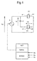
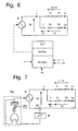
- Speiseschaltung für einen piezoelektrischen Wanderwellenmotor mit wenigstens einem Läufer, der durch Reibung von wenigstens einem Ständer mitgenommen wird, welcher von wenigstens zwei piezoelektrischen Elementen erregt wird, wobei diese piezoelektrischen Elemente jeweils einerseits mit dem Ständer und andererseits mit zwei Elektroden verbunden sind, die jeweils durch zwei Wechselspannungen (Vp, Va) gespeist werden, welche dieselbe Amplitude haben und um etwa 180° phasenverschoben sind, und zwar mit Hilfe einer einzigen Wechselspannungsquelle sowie eines Mittels zum Erzeugen der beiden phasenverschobenen Spannungen,
dadurch gekennzeichnet, dass das Mittel zum Erzeugen der beiden phasenverschobenen Spannungen aus einem in Reihe mit den erwähnten Elektroden liegenden Kondensator besteht, dessen Wert derart gewählt ist, dass für eine gegebene Frequenz der Quellenspannung die Amplitude der Spannung zwischen dem Ständer und der mit dem Kondensator in Reihe geschalteten Elektrode des piezoelektrischen Elements etwa gleich der Amplitude der Quellenspannung ist, und dass die Phasenverschiebung der Ströme in jedem piezoelektrischen Element nahe bei 90° liegt. - Speiseschaltung nach Anspruch 1, dadurch gekennzeichnet, dass in einer ersten Phase des Motorbetriebs die Speisequelle durch eine ULT (logische Verarbeitungseinheit) frequenzgesteuert wird, an deren Eingänge die Quellenspannung (Vp) und die Spannung (Va) zwischen dem Ständer und der an den Kondensator angeschlossenen Elektrode des piezoelektrischen Element angelegt sind, und dass die ULT dazu programmiert ist, um die Frequenz der Quelle derart zu justieren, dass die Amplituden der erwähnten Spannungen (Vp, Va) gleich sind.
- Speiseschaltung nach Anspruch 1, dadurch gekennzeichnet, dass die Speisequelle durch eine ULT gesteuert wird, an deren Eingängen die Spannung (Va) zwischen dem Ständer und der in Reihe mit dem Kondensator geschalteten Elektrode des piezoelektrischen Elements liegt.
- Speiseschaltung nach Anspruch 3, dadurch gekennzeichnet, dass an den Eingängen der ULT auch die Quellenspannung und/oder die Spannung an den Kondensatorklemmen liegt.
- Speiseschaltung nach Anspruch 4, dadurch gekennzeichnet, dass die ULT programmiert ist, um die Spannung zwischen dem Ständer und der in Reihe mit dem Kondensator liegenden Elektrode des piezoelektrischen Elements mit einem Bezugswert zu vergleichen.
- Speiseschaltung nach Anspruch 4, dadurch gekennzeichnet, dass die ULT dazu programmiert ist, um die Spannung zwischen dem Ständer und der mit dem Kondensator in Reihe liegenden Elektrode des piezoelektrischen Elements mit der Quellenspannung zu vergleichen, um die Phasenverschiebung oder die Amplitudendifferenz oder den Quotienten der Amplituden zu berechnen.
- Speiseschaltung nach einem der Ansprüche 3 bis 5, dadurch gekennzeichnet, dass die ULT dazu programmiert ist, um die zeitliche Ableitung der an ihren Eingängen liegenden Spannungen bzw. der Differenz zum Bezugswert zu berechnen.
- Speiseschaltung nach Anspruch 6, dadurch gekennzeichnet, das die ULT dazu programmiert ist, um die zeitliche Ableitung der erwähnten Phasenverschiebung oder der erwähnten Amplitudendifferenz oder des erwähnten Amplitudenquotienten zu berechnen.
- Speiseschaltung nach Anspruch 1, dadurch gekennzeichnet, dass die Speisequelle (S) durch eine ULT frequenzgesteuert wird, an deren Eingänge die Quellenspannung (Vp) und der Gesamtstrom (I) angelegt sind, wobei die ULT dazu programmiert ist, um die Frequenz der Quelle (S) so zu justieren, dass die Quellenspannung (Vp) und der Gesamtstrom (I) im wesentlichen in Phase sind.
- Speiseschaltung nach Anspruch 1, dadurch gekennzeichnet, dass die Speisequelle (S) durch eine ULT frequenzgesteuert wird, an deren Eingänge die Ströme (I1, I2) in den beiden Elektroden angelegt sind, wobei die ULT dazu programmiert ist, um die Frequenz der Quelle (S) so zu justieren, dass die Ströme (I1, I2) im wesentlichen um 90 phasenverschoben sind.
- Speiseschaltung nach Anspruch 1, dadurch gekennzeichnet, dass die Speisequelle (S) durch eine Phasenverriegelungsschleife (PLL) so frequenzgesteuert wird, dass die Quellenspannung (Vp) und der Gesamtstrom (I) im wesentlichen in Phase sind.
- Speiseschaltung nach einem der Ansprüche 1 bis 11, dadurch gekennzeichnet, dass sie ein zusätzliches Mittel (0; ULT) zur freiwilligen Frequenzverschiebung aufweist, wobei die Frequenz der Quelle relativ zur Resonanzfrequenz des Motors leicht verschoben wird.
Applications Claiming Priority (2)
| Application Number | Priority Date | Filing Date | Title |
|---|---|---|---|
| FR9802070A FR2775397A1 (fr) | 1998-02-20 | 1998-02-20 | Circuit d'alimentation d'un moteur piezo-electrique a onde progressive |
| FR9802070 | 1998-02-20 |
Publications (2)
| Publication Number | Publication Date |
|---|---|
| EP0938142A1 EP0938142A1 (de) | 1999-08-25 |
| EP0938142B1 true EP0938142B1 (de) | 2003-09-17 |
Family
ID=9523186
Family Applications (1)
| Application Number | Title | Priority Date | Filing Date |
|---|---|---|---|
| EP99810112A Expired - Lifetime EP0938142B1 (de) | 1998-02-20 | 1999-02-10 | Schaltungsanordnung für einen piezoelektrischen Wanderwellenmotor |
Country Status (7)
| Country | Link |
|---|---|
| US (1) | US6072265A (de) |
| EP (1) | EP0938142B1 (de) |
| JP (1) | JPH11285280A (de) |
| AT (1) | ATE250282T1 (de) |
| DE (1) | DE69911276T2 (de) |
| ES (1) | ES2136053T1 (de) |
| FR (1) | FR2775397A1 (de) |
Families Citing this family (5)
| Publication number | Priority date | Publication date | Assignee | Title |
|---|---|---|---|---|
| FR2799319B1 (fr) | 1999-10-05 | 2003-12-12 | Metabole Dev Et Conseil | Moteur ultrasonique a onde progressive |
| US7389806B2 (en) * | 2005-02-24 | 2008-06-24 | Lawrence Kates | Motorized window shade system |
| US20090308543A1 (en) * | 2008-06-13 | 2009-12-17 | Lawrence Kates | Motorized window shade system and mount |
| EP3188266B1 (de) * | 2011-06-27 | 2022-04-06 | Canon Kabushiki Kaisha | Verfahren zur herstellung eines stators für einen piezoelektrischen vibrationswellenmotor |
| US9583260B2 (en) * | 2014-07-23 | 2017-02-28 | Goodrich Corporation | System and method for increasing coupling of an axle rotary transformer |
Family Cites Families (11)
| Publication number | Priority date | Publication date | Assignee | Title |
|---|---|---|---|---|
| US4658172A (en) * | 1984-02-10 | 1987-04-14 | Canon Kabushiki Kaisha | Drive circuit for a vibration wave motor |
| GB2183371B (en) * | 1985-10-09 | 1989-09-27 | Canon Kk | Vibration wave motor and drive circuit therefor |
| US4772814A (en) * | 1986-04-25 | 1988-09-20 | Lewus Alexander J | Parallel resonant single phase motor |
| US4794294A (en) * | 1986-06-12 | 1988-12-27 | Canon Kabushiki Kaisha | Vibration wave motor |
| JP2794692B2 (ja) * | 1987-02-13 | 1998-09-10 | 株式会社ニコン | 超音波モータの駆動回路 |
| US5021700A (en) * | 1988-03-01 | 1991-06-04 | Matsushita Electric Industrial Co., Ltd. | Driving apparatus for ultrasonic motor |
| DE3939419A1 (de) * | 1989-11-29 | 1991-06-06 | Licentia Gmbh | Mehrflaechensensorsteuerung fuer einen wanderwellenmotor |
| DE69131208T2 (de) * | 1990-02-14 | 1999-09-02 | Nikon Corp. | Antriebsvorrichtung für einen Ultraschallwellenmotor |
| US5563464A (en) * | 1993-02-09 | 1996-10-08 | Olympus Optical Co., Ltd. | Circuit for rotating ultrasonic motor |
| FR2721154B1 (fr) * | 1994-06-08 | 1996-07-05 | Moulinex Sa | Circuit d'alimentation d'un moteur piézo-électrique. |
| JPH08116685A (ja) * | 1994-10-17 | 1996-05-07 | Canon Inc | 振動波モータ |
-
1998
- 1998-02-20 FR FR9802070A patent/FR2775397A1/fr not_active Withdrawn
-
1999
- 1999-02-10 ES ES99810112T patent/ES2136053T1/es active Pending
- 1999-02-10 EP EP99810112A patent/EP0938142B1/de not_active Expired - Lifetime
- 1999-02-10 DE DE69911276T patent/DE69911276T2/de not_active Expired - Fee Related
- 1999-02-10 AT AT99810112T patent/ATE250282T1/de not_active IP Right Cessation
- 1999-02-16 US US09/250,334 patent/US6072265A/en not_active Expired - Fee Related
- 1999-02-19 JP JP11041628A patent/JPH11285280A/ja not_active Withdrawn
Also Published As
| Publication number | Publication date |
|---|---|
| FR2775397A1 (fr) | 1999-08-27 |
| EP0938142A1 (de) | 1999-08-25 |
| DE69911276T2 (de) | 2004-06-17 |
| JPH11285280A (ja) | 1999-10-15 |
| US6072265A (en) | 2000-06-06 |
| ES2136053T1 (es) | 1999-11-16 |
| DE69911276D1 (de) | 2003-10-23 |
| ATE250282T1 (de) | 2003-10-15 |
Similar Documents
| Publication | Publication Date | Title |
|---|---|---|
| EP1020019B1 (de) | Gerät und verfahren zur steuerung eines synchronmotors mit permanentmagnet | |
| FR2769150A1 (fr) | Procede de commande d'un moteur, notamment a reluctance commutee et circuit de commande pour un tel moteur | |
| FR2530889A1 (fr) | Moteur electrique a courant continu sans collecteur | |
| Ogawa et al. | Stability of a photoinduced insulator-metal transition in Pr 1− x Ca x MnO 3 | |
| CH632864A5 (fr) | Appareil de reproduction de signaux d'information enregistres sur un support d'enregistrement. | |
| CH632878A5 (fr) | Dispositif moteur conprenant un moteur a courant continu sans collecteur et un circuit d'alimentation de celui-ci. | |
| FR2486328A1 (fr) | Dispositif perfectionne d'economie d'energie pour moteurs a induction | |
| EP0938142A1 (de) | Schaltungsanordnung für einen piezoelektrischen Wanderwellenmotor | |
| FR2685474A1 (fr) | Circuit d'exploitation pour capteur inductif dont l'inductance depend de la grandeur a mesurer. | |
| FR3003415A1 (fr) | Installation et procede de commande d'une machine a champ tournant | |
| FR2478400A1 (fr) | Dispositif de commande d'un moteur electrique | |
| EP0702420B1 (de) | Akustischer Oberflächenwellenmotor | |
| EP1285490B1 (de) | Verfahren zur bestimmung der rotorposition eines kollektorlosen elektromagnetischen motors und vorrichtung zur durchführung eines solchen verfahrens | |
| FR2562349A1 (fr) | Oscillateur piezo-electrique fonctionnant en mode aperiodique | |
| EP2940849A2 (de) | Elektrische stromversorgung und steuerverfahren einer solchen elektrischen stromversorgung | |
| EP0764347B1 (de) | Schaltungsanordnung für einen piezoelektrischen motor | |
| FR2724789A1 (fr) | Dispositif de commande d'un moteur synchrone | |
| FR2467504A1 (fr) | Moteur a courant continu comportant un dispositif de commutation pour faciliter le demarrage | |
| EP0113264B1 (de) | Hochfrequenz-Oszillator mit kompensiertem Isochronismusmangel | |
| WO2015040305A2 (fr) | Machine electrique comprenant au moins un capteur integre pour la detection de la position des poles magnetiques de son rotor | |
| FR2510836A1 (fr) | Moteur electrique a repulsion sans collecteur | |
| EP0507697B1 (de) | Regelung eines elektrischen Motors mit Statorwicklung, besonders für Haushaltsgerät | |
| EP0702419A1 (de) | Verbesserten Antrieb, insbesondere ein piezoelektrischer Motor | |
| FR2513453A1 (fr) | Machine et dispositif d'entrainement electriques | |
| JPH06237583A (ja) | 超音波モータ駆動回路 |
Legal Events
| Date | Code | Title | Description |
|---|---|---|---|
| PUAI | Public reference made under article 153(3) epc to a published international application that has entered the european phase |
Free format text: ORIGINAL CODE: 0009012 |
|
| AK | Designated contracting states |
Kind code of ref document: A1 Designated state(s): AT BE CH DE ES FR GB IT LI NL SE |
|
| AX | Request for extension of the european patent |
Free format text: AL;LT;LV;MK;RO;SI |
|
| REG | Reference to a national code |
Ref country code: ES Ref legal event code: BA2A Ref document number: 2136053 Country of ref document: ES Kind code of ref document: T1 |
|
| 17P | Request for examination filed |
Effective date: 20000207 |
|
| AKX | Designation fees paid |
Free format text: AT BE CH DE ES FR GB IT LI NL SE |
|
| GRAH | Despatch of communication of intention to grant a patent |
Free format text: ORIGINAL CODE: EPIDOS IGRA |
|
| RAP1 | Party data changed (applicant data changed or rights of an application transferred) |
Owner name: SOMFY |
|
| GRAS | Grant fee paid |
Free format text: ORIGINAL CODE: EPIDOSNIGR3 |
|
| GRAA | (expected) grant |
Free format text: ORIGINAL CODE: 0009210 |
|
| AK | Designated contracting states |
Kind code of ref document: B1 Designated state(s): AT BE CH DE ES FR GB IT LI NL SE |
|
| PG25 | Lapsed in a contracting state [announced via postgrant information from national office to epo] |
Ref country code: NL Free format text: LAPSE BECAUSE OF FAILURE TO SUBMIT A TRANSLATION OF THE DESCRIPTION OR TO PAY THE FEE WITHIN THE PRESCRIBED TIME-LIMIT Effective date: 20030917 Ref country code: IT Free format text: LAPSE BECAUSE OF FAILURE TO SUBMIT A TRANSLATION OF THE DESCRIPTION OR TO PAY THE FEE WITHIN THE PRESCRIBED TIME-LIMIT;WARNING: LAPSES OF ITALIAN PATENTS WITH EFFECTIVE DATE BEFORE 2007 MAY HAVE OCCURRED AT ANY TIME BEFORE 2007. THE CORRECT EFFECTIVE DATE MAY BE DIFFERENT FROM THE ONE RECORDED. Effective date: 20030917 Ref country code: GB Free format text: LAPSE BECAUSE OF FAILURE TO SUBMIT A TRANSLATION OF THE DESCRIPTION OR TO PAY THE FEE WITHIN THE PRESCRIBED TIME-LIMIT Effective date: 20030917 Ref country code: AT Free format text: LAPSE BECAUSE OF FAILURE TO SUBMIT A TRANSLATION OF THE DESCRIPTION OR TO PAY THE FEE WITHIN THE PRESCRIBED TIME-LIMIT Effective date: 20030917 |
|
| REG | Reference to a national code |
Ref country code: GB Ref legal event code: FG4D Free format text: NOT ENGLISH |
|
| REG | Reference to a national code |
Ref country code: CH Ref legal event code: EP |
|
| REF | Corresponds to: |
Ref document number: 69911276 Country of ref document: DE Date of ref document: 20031023 Kind code of ref document: P |
|
| PG25 | Lapsed in a contracting state [announced via postgrant information from national office to epo] |
Ref country code: SE Free format text: LAPSE BECAUSE OF FAILURE TO SUBMIT A TRANSLATION OF THE DESCRIPTION OR TO PAY THE FEE WITHIN THE PRESCRIBED TIME-LIMIT Effective date: 20031217 |
|
| PG25 | Lapsed in a contracting state [announced via postgrant information from national office to epo] |
Ref country code: ES Free format text: LAPSE BECAUSE OF FAILURE TO SUBMIT A TRANSLATION OF THE DESCRIPTION OR TO PAY THE FEE WITHIN THE PRESCRIBED TIME-LIMIT Effective date: 20031228 |
|
| REG | Reference to a national code |
Ref country code: CH Ref legal event code: NV Representative=s name: BUGNION S.A. |
|
| PGFP | Annual fee paid to national office [announced via postgrant information from national office to epo] |
Ref country code: DE Payment date: 20040122 Year of fee payment: 6 |
|
| PGFP | Annual fee paid to national office [announced via postgrant information from national office to epo] |
Ref country code: CH Payment date: 20040129 Year of fee payment: 6 |
|
| PG25 | Lapsed in a contracting state [announced via postgrant information from national office to epo] |
Ref country code: BE Free format text: LAPSE BECAUSE OF NON-PAYMENT OF DUE FEES Effective date: 20040228 |
|
| NLV1 | Nl: lapsed or annulled due to failure to fulfill the requirements of art. 29p and 29m of the patents act | ||
| GBV | Gb: ep patent (uk) treated as always having been void in accordance with gb section 77(7)/1977 [no translation filed] |
Effective date: 20030917 |
|
| PLBE | No opposition filed within time limit |
Free format text: ORIGINAL CODE: 0009261 |
|
| STAA | Information on the status of an ep patent application or granted ep patent |
Free format text: STATUS: NO OPPOSITION FILED WITHIN TIME LIMIT |
|
| BERE | Be: lapsed |
Owner name: *SOMFY Effective date: 20040228 |
|
| 26N | No opposition filed |
Effective date: 20040618 |
|
| PG25 | Lapsed in a contracting state [announced via postgrant information from national office to epo] |
Ref country code: LI Free format text: LAPSE BECAUSE OF NON-PAYMENT OF DUE FEES Effective date: 20050228 Ref country code: CH Free format text: LAPSE BECAUSE OF NON-PAYMENT OF DUE FEES Effective date: 20050228 |
|
| PG25 | Lapsed in a contracting state [announced via postgrant information from national office to epo] |
Ref country code: DE Free format text: LAPSE BECAUSE OF NON-PAYMENT OF DUE FEES Effective date: 20050901 |
|
| REG | Reference to a national code |
Ref country code: CH Ref legal event code: PL |
|
| PGFP | Annual fee paid to national office [announced via postgrant information from national office to epo] |
Ref country code: FR Payment date: 20070123 Year of fee payment: 9 |
|
| REG | Reference to a national code |
Ref country code: FR Ref legal event code: ST Effective date: 20081031 |
|
| PG25 | Lapsed in a contracting state [announced via postgrant information from national office to epo] |
Ref country code: FR Free format text: LAPSE BECAUSE OF NON-PAYMENT OF DUE FEES Effective date: 20080229 |