EP0938142A1 - Schaltungsanordnung für einen piezoelektrischen Wanderwellenmotor - Google Patents
Schaltungsanordnung für einen piezoelektrischen Wanderwellenmotor Download PDFInfo
- Publication number
- EP0938142A1 EP0938142A1 EP99810112A EP99810112A EP0938142A1 EP 0938142 A1 EP0938142 A1 EP 0938142A1 EP 99810112 A EP99810112 A EP 99810112A EP 99810112 A EP99810112 A EP 99810112A EP 0938142 A1 EP0938142 A1 EP 0938142A1
- Authority
- EP
- European Patent Office
- Prior art keywords
- ult
- source
- voltage
- supply circuit
- phase
- Prior art date
- Legal status (The legal status is an assumption and is not a legal conclusion. Google has not performed a legal analysis and makes no representation as to the accuracy of the status listed.)
- Granted
Links
- 239000003990 capacitor Substances 0.000 claims abstract description 18
- 230000010363 phase shift Effects 0.000 claims description 8
- 230000002747 voluntary effect Effects 0.000 claims 1
- 238000010586 diagram Methods 0.000 description 18
- 239000000523 sample Substances 0.000 description 3
- 230000006978 adaptation Effects 0.000 description 2
- 238000004458 analytical method Methods 0.000 description 2
- 238000000034 method Methods 0.000 description 2
- 241001080024 Telles Species 0.000 description 1
- 240000008042 Zea mays Species 0.000 description 1
- 238000006243 chemical reaction Methods 0.000 description 1
- 230000007423 decrease Effects 0.000 description 1
- 230000000694 effects Effects 0.000 description 1
- 230000002996 emotional effect Effects 0.000 description 1
- 235000021183 entrée Nutrition 0.000 description 1
- 230000001939 inductive effect Effects 0.000 description 1
- 239000011810 insulating material Substances 0.000 description 1
- 238000002955 isolation Methods 0.000 description 1
- 238000004519 manufacturing process Methods 0.000 description 1
- 238000005259 measurement Methods 0.000 description 1
- 230000000750 progressive effect Effects 0.000 description 1
- 230000005855 radiation Effects 0.000 description 1
- 238000007493 shaping process Methods 0.000 description 1
- 238000004804 winding Methods 0.000 description 1
Images


Classifications
-
- H—ELECTRICITY
- H02—GENERATION; CONVERSION OR DISTRIBUTION OF ELECTRIC POWER
- H02N—ELECTRIC MACHINES NOT OTHERWISE PROVIDED FOR
- H02N2/00—Electric machines in general using piezoelectric effect, electrostriction or magnetostriction
- H02N2/10—Electric machines in general using piezoelectric effect, electrostriction or magnetostriction producing rotary motion, e.g. rotary motors
- H02N2/14—Drive circuits; Control arrangements or methods
- H02N2/145—Large signal circuits, e.g. final stages
- H02N2/147—Multi-phase circuits
Definitions
- the subject of the present invention is a circuit for supplying a piezoelectric wave motor progressive comprising at least one driven rotor, by friction, by at least one stator excited by at least two piezoelectric elements connected respectively, on the one hand, to the stator and, on the other hand, to two electrodes powered by two voltages respectively alternatives of the same amplitude and phase shifted by around 90 ° using a single power source alternative and a means to generate the two phase-shifted voltages.
- Such a supply circuit is known from the patent French 2,721,154.
- it is proposed, to overcome the disadvantages of circuits previous feed including two sources feed created by devices independent power supply, power the motor piezoelectric using a single source high frequency alternative and a means of adaptation connected, on the one hand, to the power source alternative and, on the other hand, to the electrodes of piezoelectric elements to generate the two phase-shifted voltages of around 90 °.
- the means of adaptation consists of two quadrupoles, one of these '' quadrupoles including an inductance and a capacity and the other quadrupole an inductance.
- the inductances of quadrupoles can be formed by own transformer leakage inductors. It is however necessary to control these leaks by inserting an air gap so as to increase the intrinsic leakage inductance, which requires the manufacture of special transformers with radiation higher than standard transformers, this which can force to provide a shielding of the whole circuit to respect the constraints normative. Such a solution is therefore relatively heavy and expensive.
- the present invention aims to achieve a circuit as simple and light as possible.
- the supply circuit according to the invention is characterized in that the means for generating the two phase-shifted voltages consists of a capacitor in series with one of said electrodes and whose value is chosen so that for a given frequency of the source voltage, the amplitude of the voltage between the stator and the electrode of the piezoelectric element in series with the capacitor is substantially equal to the amplitude of the source voltage, and that the phase shift of currents in each piezoelectric element either close to 90 °.
- the value of the capacitor must of course be adapted to the value of the impedance of the piezoelectric elements and at the frequency of the voltage feed. This value can be determined by those skilled in the art so that two phase-shifted voltages have substantially the same amplitude and that the currents in each channel of the motor are substantially in phase quadrature.
- the power source can be, for example, piloted by a ULT (Logical Processing Unit), the presence of such a ULT further enabling determine the state of movement of the motor and its evolution, especially its speed and torque.
- ULT Logical Processing Unit
- the ULT can be used to control the frequency of the engine work.
- the voltage on the two phases of the motor i.e. the source voltage and the voltage between the stator and the electrode of the piezoelectric element connected to the capacitor, are applied to inputs of the ULT which is programmed to adjust the source frequency so that the amplitudes of said voltages are equal.
- the power source can also be controlled by frequency by applying to the ULT inputs the voltage of the source and the total current, the ULT being programmed to adjust the frequency of the source so that the voltage and the current are substantially in phase.
- Source voltage and the total current can be replaced respectively by the currents in each of electrodes, the ULT being programmed in this case so as to adjust the frequency so that said currents are substantially in quadrature of phase.
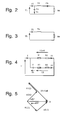
- FIG. 1 shows the diagram of a piezoelectric motor comprising two piezoelectric elements P1 and P2 powered by an alternating current source S.
- each of the elements piezoelectric is provided with two electrodes al, bl, respectively a2, b2.
- the electrodes bl and b2 are in fact constituted by the stator to which the piezoelectric elements are connected, the stator being connected to one of the terminals of source S.
- the electrode a1 of the piezoelectric element P1 is directly connected to the other terminal of the source S, while the electrode a2 of the other piezoelectric element P2 is connected to this terminal through a capacitor C.
- the capacitor C allows, on its own, to get on both tracks constituted by the two piezoelectric elements P1 and P2, two alternating voltages of the same amplitude Vp and Va and two currents phase shifted by about 90 °.
- Lm translates the mass, Cm the elasticity and Rm the conversion to thermal and mechanical power, i.e. loss and useful power.
- Co is the "blocked capacity" of the channel corresponding to the capacity formed by the separate electrodes al, bl by a thickness of insulating material.
- the ULT In a first operating phase, the ULT is used to control the working frequency f T of the motor.
- the voltages Vp and Va are applied to the inputs of the ULT which is programmed so as to adjust the frequency of the source S so that the amplitudes of the voltages Vp and Va are equal.
- ULT can be used to determine the state of movement of the motor and to control its stop and reversing its direction of rotation.
- the inversion of the direction of rotation is done by the inversion voltages Va and Vp by means of a set of switches ordered by ULT.
- the amplitude of the voltage Va can be compared to a reference value. If Va decreases it means that the torque increases. It is will be the same if Vc is compared a reference value.
- the ULT compares the voltages Va and Vp, either by calculating the phase shift of these voltages, either the difference in amplitude Vp-Va, or again the quotient of the amplitudes Vp / Va.
- piloting in power source frequency can also be by analyzing the variation of the phase shift between voltage and current or between currents.
- the voltage of source Vp and the total current I are applied to ULT inputs and the ULT is programmed to adjust the frequency of source S so that the voltage Vp and the current I are substantially in phase.
- this corresponds to the orientation of the vector U.
- a fourth embodiment is shown in Figure 7, in which the engine is again represented by its equivalent diagram.
- the ULT is replaced by a loop with PLL phase lock.
- phase locked loops for piloting frequency a piezoelectric motor. These applications are described in US Patents 4,794,294 and 4,833 358.
- Exclusive OR are applied, on the one hand, a signal representative of the total current I obtained by means of a current probe SC and a filter circuit B and shaping (Schmitt flip-flop) of the measured current by the probe and, on the other hand, a voltage corresponding to the voltage of the source Vp.
- the loop at phase lock works so that the voltage Vp and the total current I are substantially in phase as in the second embodiment.
- This latter mode of execution can be improved by the addition of a phase shift compensation element noise introduced by the filter and the setting circuit in the form of current B.
Landscapes
- General Electrical Machinery Utilizing Piezoelectricity, Electrostriction Or Magnetostriction (AREA)
Applications Claiming Priority (2)
| Application Number | Priority Date | Filing Date | Title |
|---|---|---|---|
| FR9802070A FR2775397A1 (fr) | 1998-02-20 | 1998-02-20 | Circuit d'alimentation d'un moteur piezo-electrique a onde progressive |
| FR9802070 | 1998-02-20 |
Publications (2)
| Publication Number | Publication Date |
|---|---|
| EP0938142A1 true EP0938142A1 (de) | 1999-08-25 |
| EP0938142B1 EP0938142B1 (de) | 2003-09-17 |
Family
ID=9523186
Family Applications (1)
| Application Number | Title | Priority Date | Filing Date |
|---|---|---|---|
| EP99810112A Expired - Lifetime EP0938142B1 (de) | 1998-02-20 | 1999-02-10 | Schaltungsanordnung für einen piezoelektrischen Wanderwellenmotor |
Country Status (7)
| Country | Link |
|---|---|
| US (1) | US6072265A (de) |
| EP (1) | EP0938142B1 (de) |
| JP (1) | JPH11285280A (de) |
| AT (1) | ATE250282T1 (de) |
| DE (1) | DE69911276T2 (de) |
| ES (1) | ES2136053T1 (de) |
| FR (1) | FR2775397A1 (de) |
Families Citing this family (5)
| Publication number | Priority date | Publication date | Assignee | Title |
|---|---|---|---|---|
| FR2799319B1 (fr) | 1999-10-05 | 2003-12-12 | Metabole Dev Et Conseil | Moteur ultrasonique a onde progressive |
| US7389806B2 (en) * | 2005-02-24 | 2008-06-24 | Lawrence Kates | Motorized window shade system |
| US20090308543A1 (en) * | 2008-06-13 | 2009-12-17 | Lawrence Kates | Motorized window shade system and mount |
| EP3188266B1 (de) * | 2011-06-27 | 2022-04-06 | Canon Kabushiki Kaisha | Verfahren zur herstellung eines stators für einen piezoelektrischen vibrationswellenmotor |
| US9583260B2 (en) * | 2014-07-23 | 2017-02-28 | Goodrich Corporation | System and method for increasing coupling of an axle rotary transformer |
Citations (3)
| Publication number | Priority date | Publication date | Assignee | Title |
|---|---|---|---|---|
| US4658172A (en) * | 1984-02-10 | 1987-04-14 | Canon Kabushiki Kaisha | Drive circuit for a vibration wave motor |
| JPS63202278A (ja) * | 1987-02-13 | 1988-08-22 | Nikon Corp | 超音波モ−タの駆動回路 |
| WO1995034097A1 (fr) * | 1994-06-08 | 1995-12-14 | Moulinex S.A. | Circuit d'alimentation d'un moteur piezo-electrique |
Family Cites Families (8)
| Publication number | Priority date | Publication date | Assignee | Title |
|---|---|---|---|---|
| GB2183371B (en) * | 1985-10-09 | 1989-09-27 | Canon Kk | Vibration wave motor and drive circuit therefor |
| US4772814A (en) * | 1986-04-25 | 1988-09-20 | Lewus Alexander J | Parallel resonant single phase motor |
| US4794294A (en) * | 1986-06-12 | 1988-12-27 | Canon Kabushiki Kaisha | Vibration wave motor |
| US5021700A (en) * | 1988-03-01 | 1991-06-04 | Matsushita Electric Industrial Co., Ltd. | Driving apparatus for ultrasonic motor |
| DE3939419A1 (de) * | 1989-11-29 | 1991-06-06 | Licentia Gmbh | Mehrflaechensensorsteuerung fuer einen wanderwellenmotor |
| DE69131208T2 (de) * | 1990-02-14 | 1999-09-02 | Nikon Corp. | Antriebsvorrichtung für einen Ultraschallwellenmotor |
| US5563464A (en) * | 1993-02-09 | 1996-10-08 | Olympus Optical Co., Ltd. | Circuit for rotating ultrasonic motor |
| JPH08116685A (ja) * | 1994-10-17 | 1996-05-07 | Canon Inc | 振動波モータ |
-
1998
- 1998-02-20 FR FR9802070A patent/FR2775397A1/fr not_active Withdrawn
-
1999
- 1999-02-10 ES ES99810112T patent/ES2136053T1/es active Pending
- 1999-02-10 EP EP99810112A patent/EP0938142B1/de not_active Expired - Lifetime
- 1999-02-10 DE DE69911276T patent/DE69911276T2/de not_active Expired - Fee Related
- 1999-02-10 AT AT99810112T patent/ATE250282T1/de not_active IP Right Cessation
- 1999-02-16 US US09/250,334 patent/US6072265A/en not_active Expired - Fee Related
- 1999-02-19 JP JP11041628A patent/JPH11285280A/ja not_active Withdrawn
Patent Citations (3)
| Publication number | Priority date | Publication date | Assignee | Title |
|---|---|---|---|---|
| US4658172A (en) * | 1984-02-10 | 1987-04-14 | Canon Kabushiki Kaisha | Drive circuit for a vibration wave motor |
| JPS63202278A (ja) * | 1987-02-13 | 1988-08-22 | Nikon Corp | 超音波モ−タの駆動回路 |
| WO1995034097A1 (fr) * | 1994-06-08 | 1995-12-14 | Moulinex S.A. | Circuit d'alimentation d'un moteur piezo-electrique |
Non-Patent Citations (1)
| Title |
|---|
| PATENT ABSTRACTS OF JAPAN vol. 012, no. 486 (E - 695) 19 December 1988 (1988-12-19) * |
Also Published As
| Publication number | Publication date |
|---|---|
| FR2775397A1 (fr) | 1999-08-27 |
| EP0938142B1 (de) | 2003-09-17 |
| DE69911276T2 (de) | 2004-06-17 |
| JPH11285280A (ja) | 1999-10-15 |
| US6072265A (en) | 2000-06-06 |
| ES2136053T1 (es) | 1999-11-16 |
| DE69911276D1 (de) | 2003-10-23 |
| ATE250282T1 (de) | 2003-10-15 |
Similar Documents
| Publication | Publication Date | Title |
|---|---|---|
| FR2769150A1 (fr) | Procede de commande d'un moteur, notamment a reluctance commutee et circuit de commande pour un tel moteur | |
| FR2593003A1 (fr) | Moteur a ondes vibratoires et son circuit de commande. | |
| FR2530889A1 (fr) | Moteur electrique a courant continu sans collecteur | |
| EP1275196B1 (de) | Motor mit phasenwinkelvorlauf | |
| EP0938142B1 (de) | Schaltungsanordnung für einen piezoelektrischen Wanderwellenmotor | |
| CH632878A5 (fr) | Dispositif moteur conprenant un moteur a courant continu sans collecteur et un circuit d'alimentation de celui-ci. | |
| FR2486328A1 (fr) | Dispositif perfectionne d'economie d'energie pour moteurs a induction | |
| EP0637123B1 (de) | Akustischer Oberflächenwellenmotor | |
| FR2685474A1 (fr) | Circuit d'exploitation pour capteur inductif dont l'inductance depend de la grandeur a mesurer. | |
| EP3667922A1 (de) | Durch einspritzung gerasteter oszillator mit variabler lastimpedanz | |
| FR2509065A1 (fr) | Generateur d'impulsions de reference pour une montre electronique | |
| EP0157697A1 (de) | In einem aperiodischen Modus schwingender piezoelektrischer Oszillator | |
| EP0702420A1 (de) | Akustischer Oberflächenwellenmotor | |
| EP2940849A2 (de) | Elektrische stromversorgung und steuerverfahren einer solchen elektrischen stromversorgung | |
| WO2001093414A1 (fr) | Procede de determination de la position du rotor d'un moteur electromagnetique sans collecteur et dispositif pour sa mise en oeuvre | |
| EP0702451A1 (de) | Steuervorrichtung eines Synchronmotors | |
| EP0764347B1 (de) | Schaltungsanordnung für einen piezoelektrischen motor | |
| EP0113264B1 (de) | Hochfrequenz-Oszillator mit kompensiertem Isochronismusmangel | |
| WO2015040305A2 (fr) | Machine electrique comprenant au moins un capteur integre pour la detection de la position des poles magnetiques de son rotor | |
| FR2510836A1 (fr) | Moteur electrique a repulsion sans collecteur | |
| EP0628827B1 (de) | Integrierte Schaltung mit einer Schaltung zur Pegeldetektion einer Betriebsspannung | |
| EP0702419A1 (de) | Verbesserten Antrieb, insbesondere ein piezoelektrischer Motor | |
| FR3157032A1 (fr) | Dispositif électronique et procédé de pilotage, avec régulation optimisée, d’un convertisseur d’énergie électrique comportant un résonateur, système de5 conversion d’énergie électrique associé | |
| CH720300A2 (fr) | Circuit de commande d'un moteur pas-à-pas capable de détecter un champ magnétique extérieur et procédé de détection d'un champ magnétique extérieur. | |
| FR2889344A1 (fr) | Dispositif d'entretien pour panneau plasma |
Legal Events
| Date | Code | Title | Description |
|---|---|---|---|
| PUAI | Public reference made under article 153(3) epc to a published international application that has entered the european phase |
Free format text: ORIGINAL CODE: 0009012 |
|
| AK | Designated contracting states |
Kind code of ref document: A1 Designated state(s): AT BE CH DE ES FR GB IT LI NL SE |
|
| AX | Request for extension of the european patent |
Free format text: AL;LT;LV;MK;RO;SI |
|
| REG | Reference to a national code |
Ref country code: ES Ref legal event code: BA2A Ref document number: 2136053 Country of ref document: ES Kind code of ref document: T1 |
|
| 17P | Request for examination filed |
Effective date: 20000207 |
|
| AKX | Designation fees paid |
Free format text: AT BE CH DE ES FR GB IT LI NL SE |
|
| GRAH | Despatch of communication of intention to grant a patent |
Free format text: ORIGINAL CODE: EPIDOS IGRA |
|
| RAP1 | Party data changed (applicant data changed or rights of an application transferred) |
Owner name: SOMFY |
|
| GRAS | Grant fee paid |
Free format text: ORIGINAL CODE: EPIDOSNIGR3 |
|
| GRAA | (expected) grant |
Free format text: ORIGINAL CODE: 0009210 |
|
| AK | Designated contracting states |
Kind code of ref document: B1 Designated state(s): AT BE CH DE ES FR GB IT LI NL SE |
|
| PG25 | Lapsed in a contracting state [announced via postgrant information from national office to epo] |
Ref country code: NL Free format text: LAPSE BECAUSE OF FAILURE TO SUBMIT A TRANSLATION OF THE DESCRIPTION OR TO PAY THE FEE WITHIN THE PRESCRIBED TIME-LIMIT Effective date: 20030917 Ref country code: IT Free format text: LAPSE BECAUSE OF FAILURE TO SUBMIT A TRANSLATION OF THE DESCRIPTION OR TO PAY THE FEE WITHIN THE PRESCRIBED TIME-LIMIT;WARNING: LAPSES OF ITALIAN PATENTS WITH EFFECTIVE DATE BEFORE 2007 MAY HAVE OCCURRED AT ANY TIME BEFORE 2007. THE CORRECT EFFECTIVE DATE MAY BE DIFFERENT FROM THE ONE RECORDED. Effective date: 20030917 Ref country code: GB Free format text: LAPSE BECAUSE OF FAILURE TO SUBMIT A TRANSLATION OF THE DESCRIPTION OR TO PAY THE FEE WITHIN THE PRESCRIBED TIME-LIMIT Effective date: 20030917 Ref country code: AT Free format text: LAPSE BECAUSE OF FAILURE TO SUBMIT A TRANSLATION OF THE DESCRIPTION OR TO PAY THE FEE WITHIN THE PRESCRIBED TIME-LIMIT Effective date: 20030917 |
|
| REG | Reference to a national code |
Ref country code: GB Ref legal event code: FG4D Free format text: NOT ENGLISH |
|
| REG | Reference to a national code |
Ref country code: CH Ref legal event code: EP |
|
| REF | Corresponds to: |
Ref document number: 69911276 Country of ref document: DE Date of ref document: 20031023 Kind code of ref document: P |
|
| PG25 | Lapsed in a contracting state [announced via postgrant information from national office to epo] |
Ref country code: SE Free format text: LAPSE BECAUSE OF FAILURE TO SUBMIT A TRANSLATION OF THE DESCRIPTION OR TO PAY THE FEE WITHIN THE PRESCRIBED TIME-LIMIT Effective date: 20031217 |
|
| PG25 | Lapsed in a contracting state [announced via postgrant information from national office to epo] |
Ref country code: ES Free format text: LAPSE BECAUSE OF FAILURE TO SUBMIT A TRANSLATION OF THE DESCRIPTION OR TO PAY THE FEE WITHIN THE PRESCRIBED TIME-LIMIT Effective date: 20031228 |
|
| REG | Reference to a national code |
Ref country code: CH Ref legal event code: NV Representative=s name: BUGNION S.A. |
|
| PGFP | Annual fee paid to national office [announced via postgrant information from national office to epo] |
Ref country code: DE Payment date: 20040122 Year of fee payment: 6 |
|
| PGFP | Annual fee paid to national office [announced via postgrant information from national office to epo] |
Ref country code: CH Payment date: 20040129 Year of fee payment: 6 |
|
| PG25 | Lapsed in a contracting state [announced via postgrant information from national office to epo] |
Ref country code: BE Free format text: LAPSE BECAUSE OF NON-PAYMENT OF DUE FEES Effective date: 20040228 |
|
| NLV1 | Nl: lapsed or annulled due to failure to fulfill the requirements of art. 29p and 29m of the patents act | ||
| GBV | Gb: ep patent (uk) treated as always having been void in accordance with gb section 77(7)/1977 [no translation filed] |
Effective date: 20030917 |
|
| PLBE | No opposition filed within time limit |
Free format text: ORIGINAL CODE: 0009261 |
|
| STAA | Information on the status of an ep patent application or granted ep patent |
Free format text: STATUS: NO OPPOSITION FILED WITHIN TIME LIMIT |
|
| BERE | Be: lapsed |
Owner name: *SOMFY Effective date: 20040228 |
|
| 26N | No opposition filed |
Effective date: 20040618 |
|
| PG25 | Lapsed in a contracting state [announced via postgrant information from national office to epo] |
Ref country code: LI Free format text: LAPSE BECAUSE OF NON-PAYMENT OF DUE FEES Effective date: 20050228 Ref country code: CH Free format text: LAPSE BECAUSE OF NON-PAYMENT OF DUE FEES Effective date: 20050228 |
|
| PG25 | Lapsed in a contracting state [announced via postgrant information from national office to epo] |
Ref country code: DE Free format text: LAPSE BECAUSE OF NON-PAYMENT OF DUE FEES Effective date: 20050901 |
|
| REG | Reference to a national code |
Ref country code: CH Ref legal event code: PL |
|
| PGFP | Annual fee paid to national office [announced via postgrant information from national office to epo] |
Ref country code: FR Payment date: 20070123 Year of fee payment: 9 |
|
| REG | Reference to a national code |
Ref country code: FR Ref legal event code: ST Effective date: 20081031 |
|
| PG25 | Lapsed in a contracting state [announced via postgrant information from national office to epo] |
Ref country code: FR Free format text: LAPSE BECAUSE OF NON-PAYMENT OF DUE FEES Effective date: 20080229 |