EP0937908A2 - Hydropneumatischer Dämpfer - Google Patents
Hydropneumatischer Dämpfer Download PDFInfo
- Publication number
- EP0937908A2 EP0937908A2 EP99102117A EP99102117A EP0937908A2 EP 0937908 A2 EP0937908 A2 EP 0937908A2 EP 99102117 A EP99102117 A EP 99102117A EP 99102117 A EP99102117 A EP 99102117A EP 0937908 A2 EP0937908 A2 EP 0937908A2
- Authority
- EP
- European Patent Office
- Prior art keywords
- piston
- sheath
- stem
- tube
- damper
- Prior art date
- Legal status (The legal status is an assumption and is not a legal conclusion. Google has not performed a legal analysis and makes no representation as to the accuracy of the status listed.)
- Withdrawn
Links
- 239000007788 liquid Substances 0.000 claims abstract description 12
- 230000006835 compression Effects 0.000 claims abstract description 7
- 238000007906 compression Methods 0.000 claims abstract description 7
- 238000007789 sealing Methods 0.000 claims description 6
- 239000000314 lubricant Substances 0.000 claims description 3
- 230000000284 resting effect Effects 0.000 claims description 3
- 239000011521 glass Substances 0.000 claims description 2
- 230000000087 stabilizing effect Effects 0.000 claims description 2
- 238000013016 damping Methods 0.000 claims 1
- 238000009827 uniform distribution Methods 0.000 claims 1
- 229910000831 Steel Inorganic materials 0.000 description 1
- 239000004809 Teflon Substances 0.000 description 1
- 229920006362 Teflon® Polymers 0.000 description 1
- 230000015572 biosynthetic process Effects 0.000 description 1
- 239000000428 dust Substances 0.000 description 1
- 229920001971 elastomer Polymers 0.000 description 1
- 239000000806 elastomer Substances 0.000 description 1
- 238000005461 lubrication Methods 0.000 description 1
- 239000000463 material Substances 0.000 description 1
- 239000002184 metal Substances 0.000 description 1
- 230000004048 modification Effects 0.000 description 1
- 238000012986 modification Methods 0.000 description 1
- 229920006395 saturated elastomer Polymers 0.000 description 1
- 239000010959 steel Substances 0.000 description 1
- 239000013585 weight reducing agent Substances 0.000 description 1
Images
Classifications
-
- F—MECHANICAL ENGINEERING; LIGHTING; HEATING; WEAPONS; BLASTING
- F16—ENGINEERING ELEMENTS AND UNITS; GENERAL MEASURES FOR PRODUCING AND MAINTAINING EFFECTIVE FUNCTIONING OF MACHINES OR INSTALLATIONS; THERMAL INSULATION IN GENERAL
- F16F—SPRINGS; SHOCK-ABSORBERS; MEANS FOR DAMPING VIBRATION
- F16F9/00—Springs, vibration-dampers, shock-absorbers, or similarly-constructed movement-dampers using a fluid or the equivalent as damping medium
- F16F9/32—Details
- F16F9/50—Special means providing automatic damping adjustment, i.e. self-adjustment of damping by particular sliding movements of a valve element, other than flexions or displacement of valve discs; Special means providing self-adjustment of spring characteristics
- F16F9/516—Special means providing automatic damping adjustment, i.e. self-adjustment of damping by particular sliding movements of a valve element, other than flexions or displacement of valve discs; Special means providing self-adjustment of spring characteristics resulting in the damping effects during contraction being different from the damping effects during extension, i.e. responsive to the direction of movement
-
- F—MECHANICAL ENGINEERING; LIGHTING; HEATING; WEAPONS; BLASTING
- F16—ENGINEERING ELEMENTS AND UNITS; GENERAL MEASURES FOR PRODUCING AND MAINTAINING EFFECTIVE FUNCTIONING OF MACHINES OR INSTALLATIONS; THERMAL INSULATION IN GENERAL
- F16F—SPRINGS; SHOCK-ABSORBERS; MEANS FOR DAMPING VIBRATION
- F16F9/00—Springs, vibration-dampers, shock-absorbers, or similarly-constructed movement-dampers using a fluid or the equivalent as damping medium
- F16F9/32—Details
- F16F9/36—Special sealings, including sealings or guides for piston-rods
-
- F—MECHANICAL ENGINEERING; LIGHTING; HEATING; WEAPONS; BLASTING
- F16—ENGINEERING ELEMENTS AND UNITS; GENERAL MEASURES FOR PRODUCING AND MAINTAINING EFFECTIVE FUNCTIONING OF MACHINES OR INSTALLATIONS; THERMAL INSULATION IN GENERAL
- F16F—SPRINGS; SHOCK-ABSORBERS; MEANS FOR DAMPING VIBRATION
- F16F9/00—Springs, vibration-dampers, shock-absorbers, or similarly-constructed movement-dampers using a fluid or the equivalent as damping medium
- F16F9/32—Details
- F16F9/44—Means on or in the damper for manual or non-automatic adjustment; such means combined with temperature correction
- F16F9/46—Means on or in the damper for manual or non-automatic adjustment; such means combined with temperature correction allowing control from a distance, i.e. location of means for control input being remote from site of valves, e.g. on damper external wall
Definitions
- the invention relates to a hydropneumatic damper that can be adjusted for the degree of braking in extension and in the elastic reaction during compression and is particularly suitable for forming, in combination with an identical damper, the telescopic legs of a fork for a mountain bike or other means of transport having similar requirements, so that the fork itself can be adapted to the varying conditions of use of the means of transport.
- the damper according to the invention is distinguished from known solutions by a reduced number of components, a lower weight due to the absence of opposing steel springs, and a reduced amount of liquid in the hydraulic circuit, and is characterized by its great ease of assembly and disassembly.
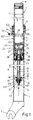
- the damper comprises a sheath 1 which, for the formation of a leg of a fork for a mountain bike, is e.g. closed at the lower end by a raised end wall 3 (see below), is provided with a lower appendage 2 in the form of a fork or bush and is optionally provided in the lower lateral region with additional appendages (not shown) to support the calliper of a disc brake.
- a sheath 1 which, for the formation of a leg of a fork for a mountain bike, is e.g. closed at the lower end by a raised end wall 3 (see below), is provided with a lower appendage 2 in the form of a fork or bush and is optionally provided in the lower lateral region with additional appendages (not shown) to support the calliper of a disc brake.
- the sheath 1 carries at its upper end other appendages of known type (indicated in part at 102, for connection by a bridge to the sheath of the other leg of the fork and for support for an optional brake with acts on the wheel rim) and ends at the top in an enlarged part having a seat 4 of diameter greater than that of the internal cavity of the sheath itself and on the bottom of which rests the upper collar 105 of a thin bush 5 (Fig. 2) which is externally of metal and internally of teflon (see below) and lines the sheath for approximately half its length. Mounted on the collar of this bush is the known closing and sealing assembly 6 with the function of wiping off dust.
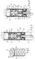
- the piston 9 is axially hollow and through it there passes with lateral sealing a tube 13 whose lower end is fixed to the end wall 3 of the sheath 1.
- the axial cavity of the piston 9 is divided into three sections whose diameters increase in the downward direction.
- a bush 14 made of a material with a low coefficient of friction is press-fitted, with the tube 13 running through it, while the intermediate section of the said cavity contains seals 15, and a washer 16 with an elastic ring 17 to keep the said seals in place is mounted in the bottom section of the same cavity.
- the tube 13 is fixed to the end wall 3 in, for example, the following way.
- the end wall 3 contains an axial through hole in which is mounted a bush 18 with its collar 118 resting on the end wall through an intermediate seal 19 and having a constriction 218 on its bottom end.
- the tube 13 is fitted accurately in the bush 18 with a lateral seal 20 in such a way as to project from the bottom of the said bush in the form of a narrowed, externally threaded section 113, on which is screwed a cup 21 which reacts against the end wall 3 and keeps the bush 18 and the tube 13 axially in position.
- a piston 22 mounted coaxially on the upper end of the tube 13 is a piston 22 in the shape of an upside-down wine glass whose waist is axially hollow as indicated at 23, the said tube 13 being screwed into this.
- An annular seal 24 is fitted around the outside of the body of the piston 22 and acts on the inside lateral surface of the stem 7.
- the waist of the piston 22 is surrounded with play by a sufficiently rigid ring 25 which forms a seal against the inside lateral surface of the stem 7 and which, when the latter is extended out of the sheath 1 (Fig. 4), abuts against and seals the head 122 of this piston, which has an external diameter smaller than the internal diameter of the stem 7.
- the ring 25 comes off the head 122 of the piston 22 and rests against the body of the same piston, where angularly equidistant apertures 26 which remain uncovered by the said ring 25 are provided.
- a series of holes 29 located around the tube 13 are inside the bush 14.
- the openings of the holes 29 may be intercepted by a variable amount by the closure member 130 on the end of a rod 30 sealed inside the tube 13 by means of a seal 14, and the same rod extends downwards until its lower end rests on an adjustment screw 31 screwed onto the lower end of the tube 13.
- the seat at the end of the tube in which the screw 31 is screwed prefferably be of a smaller diameter than the cavity of the same tube that houses the rod 30, so as to form a shoulder against which this rod 30 bears in the case in which the screw 31 is completely unscrewed from its seat.
- the screw 31 may be provided with an add-on head 131, as indicated with broken lines in Fig. 1. This will appear through a hole or slot 101 provided in the sheath 1 or may project from the bottom end of the sheath and the said head 131 may carry index markers which, viewed against external references on the sheath, indicate the axial position of the closure member 130. Means which may be devised by those skilled in the art may also be provided to allow indexed rotation of the head 131 for the additional purpose of stabilizing the screw 31 in the position to which it is moved from time to time.
- the telescopic assembly includes a lower pressure chamber A defined by the end wall 3, by the piston 9, by the tube 13 and by the sheath 1, in which a small amount of lubricant, as indicated by the level 32 in Fig. 1, can be introduced.
- Pressurized gas is introduced into the chamber A through an inflation valve 33 fitted for example to an appendage 102' at the top of the sheath 1 and which through the admission channel 34 communicates with a longitudinal aperture 35 in the bush 5, which among other things has weight-reducing holes 36, staggered in a honeycomb arrangement, in which oil-saturated air is trapped so as to contribute to the lubrication of the sliding surface between bush 5 and stem 7.
- the pressure of the gas in the chamber A constitutes the elastic means, in opposition to which the stem 7 moves as it retracts into the sheath 1 and which then causes the stem to extend when the compressive stress on the telescopic system is removed.
- the damper is provided with an intermediate pressure chamber B defined by the pistons 9 and 22 and by the lateral surface of the stem 7, and, lastly, contains an upper chamber C which, like chamber B, is initially at atmospheric pressure. Before the cap 8 is closed a quantity of oil is introduced into chamber C sufficient to completely fill chamber B and occupy a small amount of chamber C, as indicated for example in Figure 1 by the level line 37. The oil passes out of chamber C to chamber B through the apertures 26 in the piston 22 and through the holes 29 when these are outside of the bush 14.
- the space occupied by the oil in chamber C can be divided from the remaining space occupied by the air, by a floating piston 38 forming a lateral seal with the stem 7, as indicated in Figure 1 in broken lines.
- the use of the floating piston 38 to separate the oil from the air in chamber C allows the damper to operate even upside down, so that the scope of protection of the present patent application also includes a telescopic fork in which the wheel axle is connected to the free lower end of the stem, while the crossmember with the steering pin is connected to the free upper end of the sheath 1.
- This has the advantage that the adjustment screw 31 is at the top and that the oil in chamber C is against the piston 9 and therefore in the best position to lubricate the latter as it slides relative to the tube 13 and the stem as it slides relative to the bush 5.
- the inflation valve 33 may in this case be located in the region of the end wall 3 and the bush 5 need not have the longitudinal slit 35.
- the scope of the invention also includes the modification whereby pressure is generated in chamber C not by gas but by a spring or by an assembly of elastomers or by equivalent means.
Landscapes
- Engineering & Computer Science (AREA)
- General Engineering & Computer Science (AREA)
- Mechanical Engineering (AREA)
- Fluid-Damping Devices (AREA)
- Axle Suspensions And Sidecars For Cycles (AREA)
Applications Claiming Priority (2)
| Application Number | Priority Date | Filing Date | Title |
|---|---|---|---|
| IT98BO000089A IT1299850B1 (it) | 1998-02-18 | 1998-02-18 | Ammortizzatore idropneumatico, registrabile, di peso contenuto, particolarmente adatto per formare le gambe di una forcella |
| ITBO980089 | 1998-02-18 |
Publications (2)
| Publication Number | Publication Date |
|---|---|
| EP0937908A2 true EP0937908A2 (de) | 1999-08-25 |
| EP0937908A3 EP0937908A3 (de) | 2001-09-26 |
Family
ID=11342900
Family Applications (1)
| Application Number | Title | Priority Date | Filing Date |
|---|---|---|---|
| EP99102117A Withdrawn EP0937908A3 (de) | 1998-02-18 | 1999-02-03 | Hydropneumatischer Dämpfer |
Country Status (2)
| Country | Link |
|---|---|
| EP (1) | EP0937908A3 (de) |
| IT (1) | IT1299850B1 (de) |
Cited By (4)
| Publication number | Priority date | Publication date | Assignee | Title |
|---|---|---|---|---|
| WO2002066858A1 (es) * | 2001-02-23 | 2002-08-29 | Quinton Hazell España, S.A. | Amortiguador ajustable |
| WO2008085097A1 (en) * | 2007-01-10 | 2008-07-17 | öHLINS RACING AB | Framgaffel med tätningsfunktion / front fork with sealing |
| EP1947360A1 (de) * | 2007-01-20 | 2008-07-23 | ZF Friedrichshafen AG | Verstellbares Luftfeder-Dämpfer-Element |
| WO2017163874A1 (ja) * | 2016-03-23 | 2017-09-28 | 不二ラテックス株式会社 | ショックアブソーバ |
Family Cites Families (2)
| Publication number | Priority date | Publication date | Assignee | Title |
|---|---|---|---|---|
| EP0173020A2 (de) * | 1984-06-28 | 1986-03-05 | Stephen W. Simons | Motorradvorderradgabel mit Antikavitationssystem |
| DE4017924A1 (de) * | 1990-06-05 | 1991-12-12 | Boge Ag | Vorderradgabel fuer fahrraeder |
-
1998
- 1998-02-18 IT IT98BO000089A patent/IT1299850B1/it active IP Right Grant
-
1999
- 1999-02-03 EP EP99102117A patent/EP0937908A3/de not_active Withdrawn
Non-Patent Citations (1)
| Title |
|---|
| None |
Cited By (6)
| Publication number | Priority date | Publication date | Assignee | Title |
|---|---|---|---|---|
| WO2002066858A1 (es) * | 2001-02-23 | 2002-08-29 | Quinton Hazell España, S.A. | Amortiguador ajustable |
| WO2008085097A1 (en) * | 2007-01-10 | 2008-07-17 | öHLINS RACING AB | Framgaffel med tätningsfunktion / front fork with sealing |
| EP1947360A1 (de) * | 2007-01-20 | 2008-07-23 | ZF Friedrichshafen AG | Verstellbares Luftfeder-Dämpfer-Element |
| WO2017163874A1 (ja) * | 2016-03-23 | 2017-09-28 | 不二ラテックス株式会社 | ショックアブソーバ |
| CN108779827A (zh) * | 2016-03-23 | 2018-11-09 | 不二乳胶株式会社 | 减震器 |
| CN108779827B (zh) * | 2016-03-23 | 2022-02-18 | 不二乳胶株式会社 | 减震器 |
Also Published As
| Publication number | Publication date |
|---|---|
| ITBO980089A1 (it) | 1999-08-18 |
| IT1299850B1 (it) | 2000-04-04 |
| EP0937908A3 (de) | 2001-09-26 |
| ITBO980089A0 (it) | 1998-02-18 |
Similar Documents
| Publication | Publication Date | Title |
|---|---|---|
| US4311302A (en) | Shock absorber device | |
| US6991076B2 (en) | Bicycle damping enhancement system | |
| US6520524B1 (en) | Motorcycle suspension components | |
| US4795009A (en) | Twin-tube type shock absorber | |
| US8459418B2 (en) | Bicycle fork having lock-out, blow-off, and adjustable blow-off threshold | |
| US6918605B2 (en) | Inverted type front fork in two-wheeled vehicle or the like | |
| JPH10184759A (ja) | 伸縮筒型車輪案内装置 | |
| EP3040577B1 (de) | Hydraulische stossdämpfervorrichtung | |
| US4392664A (en) | Front fork of motorcycle | |
| US5682966A (en) | Rear shock absorber for bicycles | |
| US4786037A (en) | Arrangement for a spring suspension system | |
| EP0937908A2 (de) | Hydropneumatischer Dämpfer | |
| US4245825A (en) | Shock absorber for wheeled vehicle | |
| US6557674B2 (en) | Hydraulic or hydropneumatic shock absorber or telescopic suspension, equipped with built-in compensator, having small overall dimensions, easy to carry out and highly reliable | |
| EP2017495B1 (de) | Radaufhängung mit Dämpfungs- und Trennungskolben in derselben Zylinderkammer | |
| JP2870678B2 (ja) | 油圧緩衝器 | |
| JPH02109713A (ja) | サスペンション装置 | |
| JPH0514025Y2 (de) | ||
| JPH0225941Y2 (de) | ||
| JPS6243914Y2 (de) | ||
| JPS5819391Y2 (ja) | エアスプリング式シヨツクアブソ−バ | |
| JP2549361Y2 (ja) | 倒立型フロントフォークにおけるオイルロック装置 | |
| JPH0132636Y2 (de) | ||
| JPS5999134A (ja) | 緩衝器のスプリング荷重調整機構 | |
| JPS627011Y2 (de) |
Legal Events
| Date | Code | Title | Description |
|---|---|---|---|
| PUAI | Public reference made under article 153(3) epc to a published international application that has entered the european phase |
Free format text: ORIGINAL CODE: 0009012 |
|
| AK | Designated contracting states |
Kind code of ref document: A2 Designated state(s): AT BE CH CY DE DK ES FI FR GB GR IE IT LI LU MC NL PT SE |
|
| AX | Request for extension of the european patent |
Free format text: AL;LT;LV;MK;RO;SI |
|
| PUAL | Search report despatched |
Free format text: ORIGINAL CODE: 0009013 |
|
| AK | Designated contracting states |
Kind code of ref document: A3 Designated state(s): AT BE CH CY DE DK ES FI FR GB GR IE IT LI LU MC NL PT SE |
|
| AX | Request for extension of the european patent |
Free format text: AL;LT;LV;MK;RO;SI |
|
| RIC1 | Information provided on ipc code assigned before grant |
Free format text: 7F 16F 9/46 A, 7F 16F 9/06 B |
|
| AKX | Designation fees paid | ||
| REG | Reference to a national code |
Ref country code: DE Ref legal event code: 8566 |
|
| STAA | Information on the status of an ep patent application or granted ep patent |
Free format text: STATUS: THE APPLICATION IS DEEMED TO BE WITHDRAWN |
|
| 18D | Application deemed to be withdrawn |
Effective date: 20020327 |