EP0937901B1 - Pilotage du jeu radial d'un roulement - Google Patents
Pilotage du jeu radial d'un roulement Download PDFInfo
- Publication number
- EP0937901B1 EP0937901B1 EP99400391A EP99400391A EP0937901B1 EP 0937901 B1 EP0937901 B1 EP 0937901B1 EP 99400391 A EP99400391 A EP 99400391A EP 99400391 A EP99400391 A EP 99400391A EP 0937901 B1 EP0937901 B1 EP 0937901B1
- Authority
- EP
- European Patent Office
- Prior art keywords
- drainage
- lubricant
- drained
- valve
- bearing
- Prior art date
- Legal status (The legal status is an assumption and is not a legal conclusion. Google has not performed a legal analysis and makes no representation as to the accuracy of the status listed.)
- Expired - Lifetime
Links
- 238000012544 monitoring process Methods 0.000 title 1
- 239000000314 lubricant Substances 0.000 claims description 16
- 238000005096 rolling process Methods 0.000 claims description 11
- 238000005192 partition Methods 0.000 description 5
- 230000033228 biological regulation Effects 0.000 description 4
- 230000001105 regulatory effect Effects 0.000 description 3
- 230000007423 decrease Effects 0.000 description 2
- 238000010586 diagram Methods 0.000 description 2
- 230000007306 turnover Effects 0.000 description 2
- 238000011144 upstream manufacturing Methods 0.000 description 2
- 238000010276 construction Methods 0.000 description 1
- 230000001276 controlling effect Effects 0.000 description 1
- 238000001816 cooling Methods 0.000 description 1
- 230000007547 defect Effects 0.000 description 1
- 230000010339 dilation Effects 0.000 description 1
- 238000001595 flow curve Methods 0.000 description 1
- 239000012530 fluid Substances 0.000 description 1
- 238000010438 heat treatment Methods 0.000 description 1
- 238000005461 lubrication Methods 0.000 description 1
- 230000000750 progressive effect Effects 0.000 description 1
- 238000011084 recovery Methods 0.000 description 1
Images

Classifications
-
- F—MECHANICAL ENGINEERING; LIGHTING; HEATING; WEAPONS; BLASTING
- F16—ENGINEERING ELEMENTS AND UNITS; GENERAL MEASURES FOR PRODUCING AND MAINTAINING EFFECTIVE FUNCTIONING OF MACHINES OR INSTALLATIONS; THERMAL INSULATION IN GENERAL
- F16C—SHAFTS; FLEXIBLE SHAFTS; ELEMENTS OR CRANKSHAFT MECHANISMS; ROTARY BODIES OTHER THAN GEARING ELEMENTS; BEARINGS
- F16C33/00—Parts of bearings; Special methods for making bearings or parts thereof
- F16C33/30—Parts of ball or roller bearings
- F16C33/66—Special parts or details in view of lubrication
- F16C33/6637—Special parts or details in view of lubrication with liquid lubricant
- F16C33/6659—Details of supply of the liquid to the bearing, e.g. passages or nozzles
- F16C33/6674—Details of supply of the liquid to the bearing, e.g. passages or nozzles related to the amount supplied, e.g. gaps to restrict flow of the liquid
-
- F—MECHANICAL ENGINEERING; LIGHTING; HEATING; WEAPONS; BLASTING
- F16—ENGINEERING ELEMENTS AND UNITS; GENERAL MEASURES FOR PRODUCING AND MAINTAINING EFFECTIVE FUNCTIONING OF MACHINES OR INSTALLATIONS; THERMAL INSULATION IN GENERAL
- F16C—SHAFTS; FLEXIBLE SHAFTS; ELEMENTS OR CRANKSHAFT MECHANISMS; ROTARY BODIES OTHER THAN GEARING ELEMENTS; BEARINGS
- F16C19/00—Bearings with rolling contact, for exclusively rotary movement
- F16C19/52—Bearings with rolling contact, for exclusively rotary movement with devices affected by abnormal or undesired conditions
- F16C19/525—Bearings with rolling contact, for exclusively rotary movement with devices affected by abnormal or undesired conditions related to temperature and heat, e.g. insulation
-
- F—MECHANICAL ENGINEERING; LIGHTING; HEATING; WEAPONS; BLASTING
- F16—ENGINEERING ELEMENTS AND UNITS; GENERAL MEASURES FOR PRODUCING AND MAINTAINING EFFECTIVE FUNCTIONING OF MACHINES OR INSTALLATIONS; THERMAL INSULATION IN GENERAL
- F16C—SHAFTS; FLEXIBLE SHAFTS; ELEMENTS OR CRANKSHAFT MECHANISMS; ROTARY BODIES OTHER THAN GEARING ELEMENTS; BEARINGS
- F16C33/00—Parts of bearings; Special methods for making bearings or parts thereof
- F16C33/30—Parts of ball or roller bearings
- F16C33/58—Raceways; Race rings
-
- F—MECHANICAL ENGINEERING; LIGHTING; HEATING; WEAPONS; BLASTING
- F16—ENGINEERING ELEMENTS AND UNITS; GENERAL MEASURES FOR PRODUCING AND MAINTAINING EFFECTIVE FUNCTIONING OF MACHINES OR INSTALLATIONS; THERMAL INSULATION IN GENERAL
- F16C—SHAFTS; FLEXIBLE SHAFTS; ELEMENTS OR CRANKSHAFT MECHANISMS; ROTARY BODIES OTHER THAN GEARING ELEMENTS; BEARINGS
- F16C33/00—Parts of bearings; Special methods for making bearings or parts thereof
- F16C33/30—Parts of ball or roller bearings
- F16C33/66—Special parts or details in view of lubrication
- F16C33/6637—Special parts or details in view of lubrication with liquid lubricant
- F16C33/6659—Details of supply of the liquid to the bearing, e.g. passages or nozzles
- F16C33/6677—Details of supply of the liquid to the bearing, e.g. passages or nozzles from radial inside, e.g. via a passage through the shaft and/or inner ring
-
- F—MECHANICAL ENGINEERING; LIGHTING; HEATING; WEAPONS; BLASTING
- F16—ENGINEERING ELEMENTS AND UNITS; GENERAL MEASURES FOR PRODUCING AND MAINTAINING EFFECTIVE FUNCTIONING OF MACHINES OR INSTALLATIONS; THERMAL INSULATION IN GENERAL
- F16C—SHAFTS; FLEXIBLE SHAFTS; ELEMENTS OR CRANKSHAFT MECHANISMS; ROTARY BODIES OTHER THAN GEARING ELEMENTS; BEARINGS
- F16C33/00—Parts of bearings; Special methods for making bearings or parts thereof
- F16C33/30—Parts of ball or roller bearings
- F16C33/66—Special parts or details in view of lubrication
- F16C33/6637—Special parts or details in view of lubrication with liquid lubricant
- F16C33/6685—Details of collecting or draining, e.g. returning the liquid to a sump
-
- F—MECHANICAL ENGINEERING; LIGHTING; HEATING; WEAPONS; BLASTING
- F16—ENGINEERING ELEMENTS AND UNITS; GENERAL MEASURES FOR PRODUCING AND MAINTAINING EFFECTIVE FUNCTIONING OF MACHINES OR INSTALLATIONS; THERMAL INSULATION IN GENERAL
- F16C—SHAFTS; FLEXIBLE SHAFTS; ELEMENTS OR CRANKSHAFT MECHANISMS; ROTARY BODIES OTHER THAN GEARING ELEMENTS; BEARINGS
- F16C19/00—Bearings with rolling contact, for exclusively rotary movement
- F16C19/02—Bearings with rolling contact, for exclusively rotary movement with bearing balls essentially of the same size in one or more circular rows
- F16C19/04—Bearings with rolling contact, for exclusively rotary movement with bearing balls essentially of the same size in one or more circular rows for radial load mainly
- F16C19/06—Bearings with rolling contact, for exclusively rotary movement with bearing balls essentially of the same size in one or more circular rows for radial load mainly with a single row or balls
-
- F—MECHANICAL ENGINEERING; LIGHTING; HEATING; WEAPONS; BLASTING
- F16—ENGINEERING ELEMENTS AND UNITS; GENERAL MEASURES FOR PRODUCING AND MAINTAINING EFFECTIVE FUNCTIONING OF MACHINES OR INSTALLATIONS; THERMAL INSULATION IN GENERAL
- F16C—SHAFTS; FLEXIBLE SHAFTS; ELEMENTS OR CRANKSHAFT MECHANISMS; ROTARY BODIES OTHER THAN GEARING ELEMENTS; BEARINGS
- F16C2240/00—Specified values or numerical ranges of parameters; Relations between them
- F16C2240/30—Angles, e.g. inclinations
-
- F—MECHANICAL ENGINEERING; LIGHTING; HEATING; WEAPONS; BLASTING
- F16—ENGINEERING ELEMENTS AND UNITS; GENERAL MEASURES FOR PRODUCING AND MAINTAINING EFFECTIVE FUNCTIONING OF MACHINES OR INSTALLATIONS; THERMAL INSULATION IN GENERAL
- F16C—SHAFTS; FLEXIBLE SHAFTS; ELEMENTS OR CRANKSHAFT MECHANISMS; ROTARY BODIES OTHER THAN GEARING ELEMENTS; BEARINGS
- F16C2300/00—Application independent of particular apparatuses
- F16C2300/20—Application independent of particular apparatuses related to type of movement
- F16C2300/22—High-speed rotation
-
- F—MECHANICAL ENGINEERING; LIGHTING; HEATING; WEAPONS; BLASTING
- F16—ENGINEERING ELEMENTS AND UNITS; GENERAL MEASURES FOR PRODUCING AND MAINTAINING EFFECTIVE FUNCTIONING OF MACHINES OR INSTALLATIONS; THERMAL INSULATION IN GENERAL
- F16C—SHAFTS; FLEXIBLE SHAFTS; ELEMENTS OR CRANKSHAFT MECHANISMS; ROTARY BODIES OTHER THAN GEARING ELEMENTS; BEARINGS
- F16C37/00—Cooling of bearings
- F16C37/007—Cooling of bearings of rolling bearings
Definitions
- the invention consists in controlling the game radial of a bearing by regulating the amount of oil which passes through its drained outer ring.
- Some bearings are continuously lubricated by a special circuit.
- the oil usually flows out of the bearing in being projected outside by the forces of inertia that the rolling elements communicate to him.
- It exists however another design in which the oil fate of the bearing by traversing pipes pierced with through one of his rings, usually the ring exterior. It is said that this turnover (or that this ring) is drained.
- An interest of this design is to limit or even suppress projections out of the rolling and so to do without scoop recovery lubricant arranged near him.
- An advantage more important is that the drained ring is cooled more strongly by the lubricant.
- the ring The outer surface of a bearing often tends to warm up more strongly than the other and the difference of temperature between the two rings can be from several degrees in steady state of rotation. In the usual case where the outer ring is drained, this temperature difference decreases, and so the game that differential thermal expansions create around the balls or more generally elements rolling. It can be concluded that a correct application Drainage helps reduce bearing play.
- the invention consists in providing the circuit draining means for adjusting the flow of lubricant drained in order to specifically adjust the cooling the drained ring and the bearing play.
- the drainage circuit comprises through-draining drainage ducts a ring, with different inclinations in the circumferential direction of the ring.
- a lubrication circuit includes a circuit feed 4 from a tarpaulin 5, which carries a pump 6 and extends for example in the axis of a shaft 7 around which the inner ring 1 is threaded, then into supply ducts 8 radial orientation that cross this ring inside 1 and end in front of the balls 3.
- the oil flows laterally between the balls 3 and the rolling inner track 9 and is heading towards the outer ring 2 by continuing to bypass the 3.
- lateral flanges 10 close the bearing and prevent almost completely oil leaks.
- the drainage ducts 12 are the first part of a drainage system 13 which leads to the tarpaulin 5 - where the oil is poured before being returned circulation- and comprises, according to the invention, a valve 14 that can take several states of openness or closing and therefore limits the flow of oil through the drainage circuit 13.
- Figure 2 proves that increasing the drained flow reduces the rolling torque C produced by friction, and that it also reduces the temperature difference ⁇ T between rings 1 and 2 and so the game in the rolling. In order to control this game which is a important parameter of the overall dynamics of the tree line, a drained flow regulation is introduced, which varies with the circumstances of operation.
- Active regulation will include a valve which can thus be controlled by a sensor of temperature 15 placed on the outer ring 2 or on the return circuit of the lubricant 13, which opens gradually the valve as a temperature deemed just tolerable is reached on the outer ring 2, and allows the valve 14 to close gradually when this temperature is no longer reached; we could also consider replacing sensor 15 with a another, placed in the same way, which would measure the vibrations inflicted on the outer ring 2 for open the valve 14 if the vibrations reached a threshold and close it in the opposite case, because we saw that the defect of drainage produced dilations larger thermals of the outer ring 2, and therefore games in the bearing that aroused the appearance of vibrations; in another design again, the valve 14 could be controlled by a tachometer 16 measuring the rotational speed of the tree 7 to gradually reduce the drained flow when the speed of rotation increases.
- a particularity of drainage comes from what is more or less easy according to the speeds of rotation, the oil entering more or less easily into the drainage ducts 12.
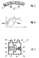
- Figure 4 shows that the flow rates of Maximum drainage offered by duct groups drainage are highly variable depending on the rotation speed and actually allow to drain properly only on a speed range relatively low: curve D121 shows that radial drainage ducts 121 (low inclination) are suitable for low speeds of rotation, whereas the corresponding curve D122 shows that the very inclined drainage ducts 122 make it possible to properly drain at higher rotational speeds high. But the total drained flow curve D, obtained by superimposing the two flows, is roughly horizontal for most rotational speeds considered, which shows that a drainage flow constant can generally be obtained, as well as any other characteristic aspect of the drained flow in according to the regime that would be dictated by efficiency considerations of the turbo-machine. The idea to divide the drainage ducts 12 into groups of distinct inclinations can obviously be extended to other inclinations and other numbers of groups. The drainage circuit 13 can be dimensioned so to obtain different returns depending on the rotation regime.
- FIG. 5 shows a valve 17 which can replace valve 14. It consists of a housing 18 divided into an upstream chamber 19 and a downstream chamber 20 by a partition 21, and conduits 22 and 23 for entering and leaving lubricant, forming part of drainage circuit 13, communicate respectively to these two branches 19 and 20.
- a plug 24 is movable in one of the rooms 20, in front of an opening 28 of the partition 21, and its movements are regulated by a rod 25 sliding to which it is attached, a bellows 26 filled with gas that separates the housing 18 on the side of the upstream chamber 19 and a spring 27 which pushes it back against the bellows 26.
- the bellows 26 becomes contract and the plug 24 is pushed in the direction opposite to the partition 21 and strangled gradually the passage of lubricant through the opening 28, that it can besides obstruct completely by sticking to the partition 21; the valve 17 is then closed.
- the closure and the opening depend on the temperature of the lubricant, and so is the drained flow.
- the lubricant outgoing from the outer ring 2, or more generally of the drained ring is at a fairly high pressure (several bars in practice), which can be exploited by plugging a device or other mechanism into the drainage circuit 13, that this pressure energy operates: it can be a fluid bearing arranged near the bearing, in the revealed disposition in the aforementioned prior patent application.
Landscapes
- Engineering & Computer Science (AREA)
- General Engineering & Computer Science (AREA)
- Mechanical Engineering (AREA)
- Rolling Contact Bearings (AREA)
Applications Claiming Priority (2)
| Application Number | Priority Date | Filing Date | Title |
|---|---|---|---|
| FR9801940 | 1998-02-18 | ||
| FR9801940A FR2775035B1 (fr) | 1998-02-18 | 1998-02-18 | Pilotage du jeu radial d'un roulement |
Publications (2)
| Publication Number | Publication Date |
|---|---|
| EP0937901A1 EP0937901A1 (fr) | 1999-08-25 |
| EP0937901B1 true EP0937901B1 (fr) | 2005-05-25 |
Family
ID=9523089
Family Applications (1)
| Application Number | Title | Priority Date | Filing Date |
|---|---|---|---|
| EP99400391A Expired - Lifetime EP0937901B1 (fr) | 1998-02-18 | 1999-02-18 | Pilotage du jeu radial d'un roulement |
Country Status (5)
| Country | Link |
|---|---|
| US (1) | US6261003B1 (enExample) |
| EP (1) | EP0937901B1 (enExample) |
| JP (1) | JP3828671B2 (enExample) |
| DE (1) | DE69925397T2 (enExample) |
| FR (1) | FR2775035B1 (enExample) |
Families Citing this family (28)
| Publication number | Priority date | Publication date | Assignee | Title |
|---|---|---|---|---|
| WO2003029671A1 (en) * | 2001-10-03 | 2003-04-10 | Vestas Wind Systems A/S | Apparatus for lubricating the bearings of an electrical power generator in a wind turbine |
| FR2841305B1 (fr) * | 2002-06-20 | 2004-09-10 | Snecma Moteurs | Palier a roulement etanche amorti a l'huile |
| FR2845138B1 (fr) * | 2002-10-01 | 2004-12-17 | Snecma Moteurs | Palier a roulement amorti a l'huile |
| JP4151472B2 (ja) * | 2003-04-25 | 2008-09-17 | 株式会社ジェイテクト | ころ軸受装置およびころ軸受の潤滑方法 |
| FR2878589B1 (fr) * | 2004-11-29 | 2008-06-13 | Snecma Moteurs Sa | Compensation de sous-alimentation en lubrifiant dans un palier inter arbres |
| DE102006012001A1 (de) * | 2006-03-16 | 2007-09-20 | Schaeffler Kg | Hochgeschwindigkeitslager, insbesondere direktgeschmiertes Spindellager für eine Werkzeugmaschine |
| DE102006011978A1 (de) * | 2006-03-16 | 2007-09-20 | Schaeffler Kg | Hochgeschwindigkeitslager, insbesondere direktgeschmiertes Spindellager für eine Werkzeugmaschine |
| DE202006008288U1 (de) * | 2006-05-23 | 2006-08-10 | Lincoln Gmbh & Co. Kg | Lageranordnung und Zumessventil hierfür |
| JP4653040B2 (ja) * | 2006-08-24 | 2011-03-16 | オークマ株式会社 | 軸受、及び軸受装置 |
| US7789567B2 (en) * | 2006-08-30 | 2010-09-07 | Honeywell International Inc. | Bearing with fluid flow bypass |
| SE530523C2 (sv) * | 2006-10-02 | 2008-07-01 | Metso Panelboard Ab | Roterande maskin, raffinör och förfarande för vibrationsstyrning av en roterande maskin |
| DE102006053237A1 (de) * | 2006-11-11 | 2008-05-29 | Pfeiffer Vacuum Gmbh | Lagermodul für eine Vakuumpumpe |
| JP4993688B2 (ja) * | 2006-11-15 | 2012-08-08 | オークマ株式会社 | 主軸潤滑装置 |
| JP5053719B2 (ja) * | 2007-06-07 | 2012-10-17 | オークマ株式会社 | 軸受潤滑装置 |
| US8979383B2 (en) | 2011-10-10 | 2015-03-17 | General Electric Company | Dynamically-lubricated bearing and method of dynamically lubricating a bearing |
| US9033581B2 (en) | 2011-10-10 | 2015-05-19 | General Electric Company | Dynamically-lubricated bearing and method of dynamically lubricating a bearing |
| US20130336608A1 (en) * | 2012-06-15 | 2013-12-19 | General Electric Company | Bearing assembly for use with a turbine engine |
| EP3567267B1 (en) * | 2012-09-24 | 2021-06-16 | NTN Corporation | Bearing device with a cooling structure |
| US9702410B2 (en) * | 2012-12-20 | 2017-07-11 | Aktiebolaget Skf | Machine arrangement |
| FR3001014B1 (fr) | 2013-01-15 | 2017-12-22 | Snecma | Bague exterieure fixe de roulement avec au moins un orifice de drainage traversant un rebord de guidage d'au moins un element roulant |
| CN103256908B (zh) * | 2013-05-22 | 2016-02-17 | 天津职业技术师范大学 | 一种变桨轴承径向游隙的确定方法 |
| CN103671558B (zh) * | 2013-12-11 | 2017-01-18 | 东方电气风电有限公司 | 风力发电机组变桨轴承润滑油路结构 |
| EP3239481A1 (en) * | 2016-04-27 | 2017-11-01 | Rolls-Royce plc | Oil chamber wall with through-holes |
| JP6555220B2 (ja) * | 2016-10-11 | 2019-08-07 | 株式会社ジェイテクト | 転がり軸受装置 |
| DE102018216618A1 (de) * | 2018-09-27 | 2020-04-02 | Zf Friedrichshafen Ag | Messanordnung für Schmierstoff |
| CN111692506B (zh) * | 2020-05-22 | 2021-07-16 | 中联重科股份有限公司 | 油泵传动联接装置及液压传动机械设备 |
| CN112610600A (zh) * | 2020-12-14 | 2021-04-06 | 人本股份有限公司 | 可调整游隙的调心滚子轴承 |
| KR102552436B1 (ko) * | 2022-07-08 | 2023-07-11 | (주)연합시스템 | 고속 베어링의 윤활유 순환 구조 |
Family Cites Families (13)
| Publication number | Priority date | Publication date | Assignee | Title |
|---|---|---|---|---|
| US3895689A (en) * | 1970-01-07 | 1975-07-22 | Judson S Swearingen | Thrust bearing lubricant measurement and balance |
| US3722967A (en) * | 1971-10-26 | 1973-03-27 | Us Navy | Low heat generation turbine engine bearing |
| US4569196A (en) * | 1984-04-20 | 1986-02-11 | Avco Corporation | Lubrication system |
| NL8700595A (nl) * | 1987-03-12 | 1988-10-03 | Skf Ind Trading & Dev | Aslagersamenstel. |
| US4738336A (en) * | 1987-04-27 | 1988-04-19 | Honeywell, Inc. | Controlled replenishing lubrication system |
| US4883082A (en) * | 1988-05-16 | 1989-11-28 | Pirkle Fred L | Temperature-responsive valve |
| US5253985A (en) * | 1990-07-04 | 1993-10-19 | Mtu Motoren- Und Turbinen-Union Friedrichshafen Gmbh | Exhaust gas turbocharger having rotor runners disposed in roller bearings |
| JPH0495693A (ja) * | 1990-08-10 | 1992-03-27 | Mitsui Seiki Kogyo Co Ltd | 軸受部の潤滑油回収方法 |
| DE4130759A1 (de) * | 1991-09-16 | 1993-03-18 | Flottweg Gmbh | Zentrifuge zur kontinuierlichen trennung von stoffen unterschiedlicher dichte |
| ES2206778T3 (es) * | 1993-03-18 | 2004-05-16 | SAURER GMBH & CO. KG | Metodo para suministrar un lubricante a un cojinete antifriccion. |
| US5469713A (en) * | 1994-01-21 | 1995-11-28 | Skf Usa, Inc. | Lubrication of refrigerant compressor bearings |
| FR2740187B1 (fr) | 1995-10-18 | 1997-11-21 | Snecma | Roulement avec drainage dynamique alimente en lubrifiant |
| KR100247232B1 (ko) * | 1997-05-17 | 2000-04-01 | 윤종용 | 열팽창 물질을 이용한 유량조절밸브 |
-
1998
- 1998-02-18 FR FR9801940A patent/FR2775035B1/fr not_active Expired - Fee Related
-
1999
- 1999-02-04 US US09/244,639 patent/US6261003B1/en not_active Expired - Lifetime
- 1999-02-05 JP JP02914699A patent/JP3828671B2/ja not_active Expired - Lifetime
- 1999-02-18 DE DE69925397T patent/DE69925397T2/de not_active Expired - Lifetime
- 1999-02-18 EP EP99400391A patent/EP0937901B1/fr not_active Expired - Lifetime
Also Published As
| Publication number | Publication date |
|---|---|
| FR2775035A1 (fr) | 1999-08-20 |
| US6261003B1 (en) | 2001-07-17 |
| DE69925397T2 (de) | 2006-02-02 |
| DE69925397D1 (de) | 2005-06-30 |
| JP3828671B2 (ja) | 2006-10-04 |
| JPH11280771A (ja) | 1999-10-15 |
| EP0937901A1 (fr) | 1999-08-25 |
| FR2775035B1 (fr) | 2000-03-10 |
Similar Documents
| Publication | Publication Date | Title |
|---|---|---|
| EP0937901B1 (fr) | Pilotage du jeu radial d'un roulement | |
| EP1715141B1 (fr) | Dispositif de régulation du débit d'air circulant dans un arbre rotatif d'une turbomachine | |
| EP0083266B1 (fr) | Turbomachine multi-corps comportant un palier inter-arbres | |
| EP3277938B2 (fr) | Refroidissement du circuit d'huile d'une turbomachine | |
| FR2955168A1 (fr) | Vanne de commande pour circuit de circulation de liquide | |
| EP2307737B1 (fr) | Compresseur axialo-centrifuge a systeme de pilotage de jeux | |
| JP5031031B2 (ja) | 風力発電装置 | |
| EP3864297B1 (fr) | Module de soufflante a pales a calage variable | |
| FR2552203A1 (fr) | Pompe a lubrifiant reglable | |
| BE1024081B1 (fr) | Refroidissement de turbomachine par evaporation | |
| WO2012052658A2 (fr) | Dispositif de lubrification avec vanne de derivation. | |
| CA2952506A1 (fr) | Dispositif et procede de lubrification d'un palier a roulement de turbomachine | |
| FR3087222A1 (fr) | Circuit d'huile de lubrification d'une turbomachine, turbomachine et son procede de regulation | |
| EP2855885A1 (fr) | Circuit de fluide dans une turbomachine | |
| WO2014131973A1 (fr) | Procede et dispositif de regulation de refroidissement d'huile d'une turbomachine | |
| US9988927B2 (en) | Housing for a gas turbine, aircraft engine, and a process for operating a gas turbine | |
| EP3377731B1 (fr) | Aube équipée d'un système de refroidissement, distributeur et turbomachine associés | |
| FR2614660A1 (fr) | Dispositif hydrostatique de passage tournant, a element compensateur integre | |
| WO2024056975A1 (fr) | Dispositif de guidage d'un arbre de turbomachine d'aeronef | |
| FR3108934A1 (fr) | Dispositif de drainage pour une turbomachine d’aeronef | |
| FR2508546A1 (fr) | Mecanisme de manoeuvre thermosensible | |
| WO2023175282A1 (fr) | Lubrification et refroidissement d'un equipement d'une turbomachine d'aéronef | |
| FR3091903A1 (fr) | Gicleur de liquide lubrifiant à débit limité | |
| EP3891364B1 (fr) | Procédé de refroidissement d'un carter de turbine pour une turbomachine | |
| FR2937088A1 (fr) | Distributeur de fluide dans une turbomachine |
Legal Events
| Date | Code | Title | Description |
|---|---|---|---|
| PUAI | Public reference made under article 153(3) epc to a published international application that has entered the european phase |
Free format text: ORIGINAL CODE: 0009012 |
|
| 17P | Request for examination filed |
Effective date: 19990304 |
|
| AK | Designated contracting states |
Kind code of ref document: A1 Designated state(s): DE FR GB |
|
| AX | Request for extension of the european patent |
Free format text: AL;LT;LV;MK;RO;SI |
|
| AKX | Designation fees paid |
Free format text: DE FR GB |
|
| 17Q | First examination report despatched |
Effective date: 20040511 |
|
| GRAP | Despatch of communication of intention to grant a patent |
Free format text: ORIGINAL CODE: EPIDOSNIGR1 |
|
| GRAS | Grant fee paid |
Free format text: ORIGINAL CODE: EPIDOSNIGR3 |
|
| RAP1 | Party data changed (applicant data changed or rights of an application transferred) |
Owner name: SNECMA MOTEURS |
|
| GRAA | (expected) grant |
Free format text: ORIGINAL CODE: 0009210 |
|
| AK | Designated contracting states |
Kind code of ref document: B1 Designated state(s): DE FR GB |
|
| REG | Reference to a national code |
Ref country code: GB Ref legal event code: FG4D Free format text: NOT ENGLISH |
|
| GBT | Gb: translation of ep patent filed (gb section 77(6)(a)/1977) |
Effective date: 20050525 |
|
| REF | Corresponds to: |
Ref document number: 69925397 Country of ref document: DE Date of ref document: 20050630 Kind code of ref document: P |
|
| RAP2 | Party data changed (patent owner data changed or rights of a patent transferred) |
Owner name: SNECMA |
|
| PLBE | No opposition filed within time limit |
Free format text: ORIGINAL CODE: 0009261 |
|
| STAA | Information on the status of an ep patent application or granted ep patent |
Free format text: STATUS: NO OPPOSITION FILED WITHIN TIME LIMIT |
|
| 26N | No opposition filed |
Effective date: 20060228 |
|
| REG | Reference to a national code |
Ref country code: FR Ref legal event code: CD |
|
| REG | Reference to a national code |
Ref country code: FR Ref legal event code: PLFP Year of fee payment: 18 |
|
| REG | Reference to a national code |
Ref country code: FR Ref legal event code: PLFP Year of fee payment: 19 |
|
| REG | Reference to a national code |
Ref country code: FR Ref legal event code: PLFP Year of fee payment: 20 |
|
| REG | Reference to a national code |
Ref country code: FR Ref legal event code: CD Owner name: SAFRAN AIRCRAFT ENGINES, FR Effective date: 20170717 |
|
| PGFP | Annual fee paid to national office [announced via postgrant information from national office to epo] |
Ref country code: DE Payment date: 20180122 Year of fee payment: 20 Ref country code: GB Payment date: 20180122 Year of fee payment: 20 |
|
| PGFP | Annual fee paid to national office [announced via postgrant information from national office to epo] |
Ref country code: FR Payment date: 20180123 Year of fee payment: 20 |
|
| REG | Reference to a national code |
Ref country code: DE Ref legal event code: R071 Ref document number: 69925397 Country of ref document: DE |
|
| REG | Reference to a national code |
Ref country code: GB Ref legal event code: PE20 Expiry date: 20190217 |
|
| PG25 | Lapsed in a contracting state [announced via postgrant information from national office to epo] |
Ref country code: GB Free format text: LAPSE BECAUSE OF EXPIRATION OF PROTECTION Effective date: 20190217 |