EP0937806A2 - Device for continuously passing a treating gas through a textile material or the like - Google Patents
Device for continuously passing a treating gas through a textile material or the like Download PDFInfo
- Publication number
- EP0937806A2 EP0937806A2 EP99103271A EP99103271A EP0937806A2 EP 0937806 A2 EP0937806 A2 EP 0937806A2 EP 99103271 A EP99103271 A EP 99103271A EP 99103271 A EP99103271 A EP 99103271A EP 0937806 A2 EP0937806 A2 EP 0937806A2
- Authority
- EP
- European Patent Office
- Prior art keywords
- drum
- clamping
- metal strips
- groove
- clamping groove
- Prior art date
- Legal status (The legal status is an assumption and is not a legal conclusion. Google has not performed a legal analysis and makes no representation as to the accuracy of the status listed.)
- Granted
Links
Images

Classifications
-
- F—MECHANICAL ENGINEERING; LIGHTING; HEATING; WEAPONS; BLASTING
- F26—DRYING
- F26B—DRYING SOLID MATERIALS OR OBJECTS BY REMOVING LIQUID THEREFROM
- F26B13/00—Machines and apparatus for drying fabrics, fibres, yarns, or other materials in long lengths, with progressive movement
- F26B13/10—Arrangements for feeding, heating or supporting materials; Controlling movement, tension or position of materials
- F26B13/14—Rollers, drums, cylinders; Arrangement of drives, supports, bearings, cleaning
- F26B13/16—Rollers, drums, cylinders; Arrangement of drives, supports, bearings, cleaning perforated in combination with hot air blowing or suction devices, e.g. sieve drum dryers
-
- D—TEXTILES; PAPER
- D06—TREATMENT OF TEXTILES OR THE LIKE; LAUNDERING; FLEXIBLE MATERIALS NOT OTHERWISE PROVIDED FOR
- D06B—TREATING TEXTILE MATERIALS USING LIQUIDS, GASES OR VAPOURS
- D06B23/00—Component parts, details, or accessories of apparatus or machines, specially adapted for the treating of textile materials, not restricted to a particular kind of apparatus, provided for in groups D06B1/00 - D06B21/00
- D06B23/02—Rollers
- D06B23/025—Perforated rollers
-
- D—TEXTILES; PAPER
- D21—PAPER-MAKING; PRODUCTION OF CELLULOSE
- D21F—PAPER-MAKING MACHINES; METHODS OF PRODUCING PAPER THEREON
- D21F5/00—Dryer section of machines for making continuous webs of paper
- D21F5/18—Drying webs by hot air
- D21F5/182—Drying webs by hot air through perforated cylinders
Abstract
Description
Die Erfindung bezieht sich auf eine Vorrichtung zum durchströmenden, kontinuierlichen Behandeln von bahnförmigem Textilgut, Vliesen oder Papier mit einem gasförmigen in der Vorrichtung umgewälzten Behandlungsmittel, mit einer unter Saugzug stehenden, stirnseitig Böden aufweisenden durchlässigen Trommel als Transportelement, welche an ihrem Umfang mit einem siebförmigen oder gelochten Belag bedeckt ist, wobei zwischen den Böden der Trommel mit den Böden fest verbundene Blechstreifen sich von Boden zu Boden erstrecken, deren Breitenausdehnung sich in radialer Richtung ertreckt.The invention relates to a device for flowing, continuous Treatment of web-like textile goods, nonwovens or paper with a gaseous one in the device circulated treatment agent, with a suction standing permeable drum with bottoms on the front as a transport element, which is covered with a sieve-shaped or perforated covering on its circumference is, sheet metal strips firmly connected to the bottoms between the bottoms of the drum extend from floor to floor, the width of which extends in radial Direction stretched.
Eine Vorrichtung dieser Art ist durch die DE 38 21 330 A1 bekannt. Sie hat den Vorteil, daß sie optimal luftdurchlässig ist, ohne daß dadurch die Stabilität der Trommel vermindert ist. Ein weiterer Vorteil ist die an dieser Vorrichtung verwirklichte Schraubkonstruktion. Ohne auf die vorbekannte Schweißkonstruktion zurückgreifen zu müssen, sind auf diese Weise alle Trommelmantelelemente über die geschraubten Stegverbindungen durch die in Umfangsrichtung verlaufenden Verbindungsstege hindurch mit den längs über die Trommel sich erstreckenden Blechstreifen rund über die Trommel fest miteinander verbunden. Die so nachteiligen Gefügeverwandlungen im Metall beim Herstellen von ansonsten notwendigen Schweißnähten sind bei dieser Schraubkonstruktion vermieden.A device of this type is known from DE 38 21 330 A1. It has the advantage that it is optimally permeable to air without reducing the stability of the drum is. Another advantage is the screw construction realized on this device. Without having to resort to the previously known welded construction, In this way, all drum casing elements are screwed on the bridge connections through the connecting webs running in the circumferential direction the sheet metal strip extending longitudinally over the drum all over the drum firmly connected. The disadvantageous structural changes in the metal in the Manufacturing of otherwise necessary weld seams are with this screw construction avoided.
Gleichgültig ob nun die Trommelmantelkonstruktion geschweißt oder mit den Schraubverbindungen hergestellt ist, die Verbindung der Blechstreifen mit den Böden der Trommel, also einmal mit einem Boden und einmal mit dem Düsenstern, durch den der Ventilator den Innenraum der Trommel unter Saugzug setzt, ist bei der Benutzung in der Praxis stärkeren thermischen Belastungen ausgesetzt. Die Böden haben eine größere Wärmekapazität als die Blechstreifen. Wenn beim Einlauf eines kalten Gutes in das aufgeheizte Trommelgehäuse die Blechstreifen beim Kontakt mit dem Gut schockartig abkühlen, so gilt dies zunächst nicht für die Böden, so daß es größere Spannungen im Material gibt, die zu Rissen oder Verbeulungen an der Trommel führen. Dies ist unabhängig von der Trommelkonstruktion, also ob sie geschweißt oder geschraubt ist.Regardless of whether the drum shell construction is welded or with the screw connections is made, the connection of the metal strips with the bottoms of the Drum, once with a bottom and once with the nozzle star through which the Fan sets the interior of the drum under suction when in use exposed to greater thermal loads in practice. The floors have a larger one Heat capacity than the metal strips. If when a cold good comes in the heated drum housing shocked the metal strips when they came into contact with the goods cool down, this initially does not apply to the floors, so that there are greater tensions in the material that cause cracks or dents on the drum. This is regardless of the drum construction, i.e. whether it is welded or screwed.
Die unterschiedlichen Wärmeausdehnungserscheinungen kann man in den Griff bekommen durch richtige Wahl von unterschiedlichen Materialien für einerseits die Trommelböden und für andererseits die einzelnen Elemente der luftdurchlässigen Trommelkonstruktion. Wesentlich ist aber die stabile Befestigung der Blechstreifen mit den Trommelböden. Diese kann mittels Schweißnähten erfolgen, die jedoch bei der Herstellung zu Wärmespannungen im Material führen. Besser ist da die Schraubkonstruktion, jedoch ist diese notgedrungen auf die Dimension der Schraube beschränkt, es kommt zu hohen lokalen Belastungen z. B. der Kanten der Schraublöcher, so daß die Schraubkonstruktion auch nicht die einwandfreie Lösung sein kann.The different phenomena of thermal expansion can be managed through the right choice of different materials for the one hand Drum bottoms and, on the other hand, the individual elements of the air-permeable Drum construction. What is essential, however, is the stable fastening of the metal strips the drum bottoms. This can be done by means of welds, but at the Manufacturing lead to thermal stresses in the material. The screw construction is better, however, this is necessarily limited to the size of the screw, there are high local loads, e.g. B. the edges of the screw holes, so that the screw construction cannot be the perfect solution either.
Der Erfindung liegt die Aufgebe zugrunde, eine Verbindung zwischen den Blechstreifen und dem jeweils benachbarten Boden der Trommel zu schaffen, die den Vorteil der beiden genannten Befestigungsarten vereint, jedoch deren Nachteile vermeidet.The invention is based on the tasks, a connection between the metal strips and to create the adjacent bottom of the drum, which takes advantage of combines the two types of fastening mentioned, but avoids their disadvantages.
Ausgehend von der Trommelkonstruktion mit den Blechstreifen anfangs genannter Art sieht die Erfindung zur Lösung der gestellten Aufgabe vor, daß die Blechstreifen über ihre gesamte radial ausgerichtete Höhe fest, jedoch lösbar mit den zugeordneten Böden verbunden sind. Dies ist mit Vorteil mit einer Klemmverbindung möglich, die die Streifen über ihre ganze Höhe stabil einklemmt. Eine denkbare konstruktive Lösung ist gegeben, wenn der Boden in der radialen Höhe der Anordnung der Blechstreifen für je zwei Blechstreifen eine radial ausgerichtete Klemmnut aufweist, deren Öffnungsquerschnitt dem Abstand der zwei benachbarten Blechstreifen entspricht.Starting from the drum construction with the metal strips initially mentioned The invention provides for solving the problem that the sheet metal strips over their entire radially aligned height is fixed, but detachable with the assigned floors are connected. This is advantageously possible with a clamp connection that Strips stuck firmly over their entire height. A conceivable constructive solution is given when the bottom in the radial height of the arrangement of the metal strips for each two sheet metal strips has a radially aligned clamping groove, the opening cross section corresponds to the distance between the two adjacent metal strips.
Eine Vorrichtung der erfindungsgemäßen Art ist in der Zeichnung beispielhaft dargestellt. Anhand dieser sollen noch weitere konstruktive Details beschrieben werden. Es zeigen:
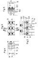
- Fig. 1
- einen Schnitt längs durch eine übliche Siebtrommelvorrichtung, deren Blechmantel hier aus einer streifenförmigen Blechmantelstruktur mit außen aufgelegtem Siebgewebe besteht,
- Fig. 2
- das Detail III der Fig. 1 in einer Draufsicht auf die Siebtrommelkonstruktion im Bereich eines stirnseitigen Trommelbodens,
- Fig. 3
- die Befestigung der Blechstreifen an dem Trommelboden in der Sicht entlang des Schnittes III - III in der Fig. 2,
- Fig. 4
- einen Schnitt durch die Befestigung am Trommelboden entlang der Linie IV - IV in der Fig. 3 und
- Fig. 5
- einen Schnitt durch die Befestigung am Trommelboden entlang der Linie V - V in der Fig. 3.
- Fig. 1
- 2 shows a section along a conventional screen drum device, the sheet metal jacket of which consists here of a strip-shaped sheet metal jacket structure with screen fabric placed on the outside,
- Fig. 2
- the detail III of FIG. 1 in a plan view of the screen drum construction in the region of an end drum bottom,
- Fig. 3
- the attachment of the sheet metal strips to the drum bottom in the view along the section III - III in Fig. 2,
- Fig. 4
- a section through the attachment to the drum base along the line IV - IV in Fig. 3 and
- Fig. 5
- 3 shows a section through the attachment to the drum base along the line V - V in FIG. 3.
Eine Siebtrommelvorrichtung besteht grundsätzlich aus einem etwa rechteckigen Gehäuse
1, das durch eine Zwischenwand 2 in einen Behandlungsraum 3 und einen
Ventilatorraum 4 unterteilt ist. Im Behandlungsraum 3 ist die Siebtrommel 5 und konzentrisch
zu dieser im Ventilatorraum 4 ein Ventilator 6 drehbar gelagert. Selbstverständlich
kann der Ventilatorraum auch in einem von dem Siebtrommelgehäuse 1
abgetrennten, hier nicht dargestellten, gesonderten Ventilatorgehäuse angeordnet
sein. Jedenfalls setzt der Ventilator das Innere der Trommel 5 unter Saugzug. Auch ist
die Trommelkonstruktion an einer Naßbehandlungsvorrichtung, die auch nur zum Absaugen
von Flüssigkeit dienen kann, Gegenstand des Patentes. Die Gesamtkonstruktion
ist dann entsprechend anzupassen.A screen drum device basically consists of an approximately
Gemäß der Fig. 1 sind ober- und unterhalb des Ventilators 6 jeweils Heizaggregate 7
angeordnet, die aus mit Heizmedium durchflossenen Rohren bestehen. Die Siebtrommel
ist in dem nicht vom Textilgut 10 bedeckten Bereich innen von einer nicht dargestellten
Innenabdeckung gegen den Saugzug abgedeckt. Die das Textilgut 10 tragende
Mantelstruktur der Siebtrommel ist durch die weiter unten beschriebene Blechstreifenstruktur
gebildet. Diese ist außen von einem feinmaschigem Sieb 9 umschlungen,
das an der Stirnseite der Trommel an dem Boden 12 und an dem Boden 11 mit
dem Düsenstern 11' gespannt gehalten ist. 1, there are
Die Blechstreifenstruktur besteht aus axial ausgerichteten Blechstreifen 13, deren radial
ausgerichtete Höhe aus den Figuren 3 - 5 hervorgeht. Damit liegt also der
siebförmige Belag 9 gemäß Fig. 1 nur auf den radial außen angeordneten Kanten der
Blechstreifen 13 auf.The sheet metal strip structure consists of axially aligned
Die Blechstreifen 13 sind gemäß Fig. 2 mit einem definierten Abstand nebeneinander
an den beiden Böden 11, 12 befestigt. Der Abstand wird durch die Länge der zwischen
allen Blechstreifen 13 anzuordnenden Verbindungsstege 14 bestimmt, durch die letztlich
zur Rundumbefestigung Schrauben 15, 16 hindurchgeschoben sind. Zur axialen
Befestigung der Blechstreifen 13 an den Böden 11, 12 dient eine Klemmkonstruktion,
die die Blechstreifen 13 über ihre ganze radiale Höhe faßt. Die Klemmkonstruktion ist
in einem gesonderten Zentrierring 17 eingebracht, der seinerseits über Schrauben 18
mit dem jeweiligen Boden 11, 12 verbunden ist. Die Befestigung des Zentrierrings 17
an dem zugeordneten Boden 11, 12 mittels der Schrauben 18 erfolgt im Wechsel zur
Befestigung der Blechstreifen 13 am Zentrierring 17 mittels der Schrauben 23, 24,
siehe dazu Fig. 2 und 3.The
Wie aus Fig. 2 ersichtlich sind in den Zentrierring 17 für je zwei Blechstreifen 13 eine
radial ausgerichtete Klemmnut 19 eingebracht, deren Öffnungsquerschnitt dem Abstand
der zwei benachbarten Blechstreifen 13 entspricht. In Richtung der Enden 13'
der Blechstreifen 13 verengt sich dann die Klemmnut 19 zur Bildung der Klemmbacken
20, 21 konisch. In die Klemmnut 19 paßt ein Klemmstift 22, dessen radial ausgerichtete
Seitenwangen der Neigung der Klemmbacken 20, 21 der Klemmnut 19 angepaßt
sind, und zwar derart, daß der Klemmstift 22 in seiner Breitendimension der Klemmnut
19 abzüglich der Materialdicke der beiden benachbarten Blechstreifen 13 entspricht.
Wird nun der Klemmstift 22 mittels der beiden Schrauben 23 und 24 gemäß Fig. 5 an
den Zentrierring 17 herangezogen, so werden die Enden der beiden eingeklemmten
Blechstreifen 13 über ihre ganze Höhe und auch eine gewisse Breite, also vollflächig,
fest an dem Zentrierring 17 gehalten. Eine dauerhaft stabile Befestigung der
Blechstreifen 13 an den Böden 11, 12 ist erzielt.As can be seen from FIG. 2, one is in the
Claims (10)
Applications Claiming Priority (2)
| Application Number | Priority Date | Filing Date | Title |
|---|---|---|---|
| DE19806614 | 1998-02-18 | ||
| DE19806614A DE19806614A1 (en) | 1998-02-18 | 1998-02-18 | Device for flowing, continuous treatment of textile goods or the like. |
Publications (3)
| Publication Number | Publication Date |
|---|---|
| EP0937806A2 true EP0937806A2 (en) | 1999-08-25 |
| EP0937806A3 EP0937806A3 (en) | 2000-05-24 |
| EP0937806B1 EP0937806B1 (en) | 2003-05-07 |
Family
ID=7858061
Family Applications (1)
| Application Number | Title | Priority Date | Filing Date |
|---|---|---|---|
| EP99103271A Expired - Lifetime EP0937806B1 (en) | 1998-02-18 | 1999-02-13 | Device for continuously passing a treating gas through a textile material or the like |
Country Status (3)
| Country | Link |
|---|---|
| US (1) | US6088927A (en) |
| EP (1) | EP0937806B1 (en) |
| DE (2) | DE19806614A1 (en) |
Cited By (1)
| Publication number | Priority date | Publication date | Assignee | Title |
|---|---|---|---|---|
| JP2004504505A (en) * | 2000-07-18 | 2004-02-12 | フライスナー ゲゼルシャフト ミット ベシュレンクテル ハフツング ウント コンパニー マシーネンファブリーク | Apparatus for continuous treatment of textile products or the like with treatment medium flowing through |
Families Citing this family (1)
| Publication number | Priority date | Publication date | Assignee | Title |
|---|---|---|---|---|
| ITBO20020369A1 (en) * | 2002-06-12 | 2003-12-12 | Marposs Spa | APPARATUS FOR THE CONTROL OF DIMENSIONAL AND GEOMETRIC FEATURES OF PINS |
Citations (1)
| Publication number | Priority date | Publication date | Assignee | Title |
|---|---|---|---|---|
| DE3821330A1 (en) * | 1988-01-30 | 1989-12-28 | Fleissner Maschf Ag | Apparatus for the throughflow treatment of textile material, paper or the like |
Family Cites Families (3)
| Publication number | Priority date | Publication date | Assignee | Title |
|---|---|---|---|---|
| DE3802791A1 (en) * | 1988-01-30 | 1989-08-10 | Fleissner Maschf Ag | DEVICE FOR FLOWING TREATMENT OF TEXTILE GOODS, PAPER OD. DGL. |
| DE3907421A1 (en) * | 1989-03-08 | 1990-09-20 | Fleissner Maschf Ag | DEVICE FOR FLOWING TREATMENT OF TEXTILE GOODS, PAPER OD. DGL. |
| DE4422508C1 (en) * | 1994-06-28 | 1996-02-15 | Fleissner Maschf Gmbh Co | Drum appts for continuous wet or dry treatment of textiles |
-
1998
- 1998-02-18 DE DE19806614A patent/DE19806614A1/en not_active Withdrawn
-
1999
- 1999-02-13 DE DE59905386T patent/DE59905386D1/en not_active Expired - Fee Related
- 1999-02-13 EP EP99103271A patent/EP0937806B1/en not_active Expired - Lifetime
- 1999-02-18 US US09/251,726 patent/US6088927A/en not_active Expired - Lifetime
Patent Citations (1)
| Publication number | Priority date | Publication date | Assignee | Title |
|---|---|---|---|---|
| DE3821330A1 (en) * | 1988-01-30 | 1989-12-28 | Fleissner Maschf Ag | Apparatus for the throughflow treatment of textile material, paper or the like |
Cited By (1)
| Publication number | Priority date | Publication date | Assignee | Title |
|---|---|---|---|---|
| JP2004504505A (en) * | 2000-07-18 | 2004-02-12 | フライスナー ゲゼルシャフト ミット ベシュレンクテル ハフツング ウント コンパニー マシーネンファブリーク | Apparatus for continuous treatment of textile products or the like with treatment medium flowing through |
Also Published As
| Publication number | Publication date |
|---|---|
| EP0937806A3 (en) | 2000-05-24 |
| EP0937806B1 (en) | 2003-05-07 |
| US6088927A (en) | 2000-07-18 |
| DE19806614A1 (en) | 1999-08-19 |
| DE59905386D1 (en) | 2003-06-12 |
Similar Documents
| Publication | Publication Date | Title |
|---|---|---|
| DE4422508C1 (en) | Drum appts for continuous wet or dry treatment of textiles | |
| EP1612328B1 (en) | Apparatus for continuous drying of a fibre web | |
| EP0841424B1 (en) | Device for hydraulic needling of nonwoven fabrics, tissues | |
| DE2342421C3 (en) | Drum with an annular lattice construction | |
| EP0997577B1 (en) | Headbox | |
| EP0678613B1 (en) | Device for forcing a treating fluid through a textile material | |
| EP0937806B1 (en) | Device for continuously passing a treating gas through a textile material or the like | |
| EP1678452A1 (en) | Veneer dryer | |
| EP0315961A2 (en) | Apparatus for forcing a treating material through a textile material | |
| EP0753619B1 (en) | Device for passing a treating fluid through a textile material or the like | |
| DE19819340A1 (en) | Device for the heat treatment of permeable webs | |
| AT411910B (en) | DEVICE FOR CONTINUOUS DRYING OF A FIBER web | |
| EP1048914A2 (en) | Sieve drum drying apparatus for drying pervious material webs | |
| DE10001535A1 (en) | Plate drum to support a nonwoven at needle bonding jets is composed of plate rings locked together by plate strips in a stable structure to support the woven mesh mantle which carries the material being bonded | |
| EP0950747A1 (en) | Device for continuously passing a hot treating fluid through textile material or the like | |
| EP1301659B1 (en) | Device for treating textiles or similar in a continuous stream | |
| EP1563134A1 (en) | Device for treating web-type goods with a flowing or pressure medium | |
| DE3802791A1 (en) | DEVICE FOR FLOWING TREATMENT OF TEXTILE GOODS, PAPER OD. DGL. | |
| EP0385208B1 (en) | Apparatus for forcing a treating material through a textile material | |
| EP0979894A1 (en) | Device for continuously passing a hot treating fluid through textile material or the like | |
| DE10111335A1 (en) | Permeable drum, for the heat treatment of web materials, has a tubular woven mesh cladding around the perforated mantle, held by clamping rings supported by radial springs to allow expansion/contraction without distortion | |
| WO2004073867A2 (en) | Device comprising a sieve drum, which is radially flown through by a fluid, and permeable bellows that surround the sieve drum | |
| DE3821330A1 (en) | Apparatus for the throughflow treatment of textile material, paper or the like | |
| DE19636592A1 (en) | Sieve drum | |
| DE102015224295A1 (en) | Device for the discharge of liquid |
Legal Events
| Date | Code | Title | Description |
|---|---|---|---|
| PUAI | Public reference made under article 153(3) epc to a published international application that has entered the european phase |
Free format text: ORIGINAL CODE: 0009012 |
|
| AK | Designated contracting states |
Kind code of ref document: A2 Designated state(s): DE FR GB IT |
|
| AX | Request for extension of the european patent |
Free format text: AL;LT;LV;MK;RO;SI |
|
| PUAL | Search report despatched |
Free format text: ORIGINAL CODE: 0009013 |
|
| AK | Designated contracting states |
Kind code of ref document: A3 Designated state(s): AT BE CH CY DE DK ES FI FR GB GR IE IT LI LU MC NL PT SE |
|
| AX | Request for extension of the european patent |
Free format text: AL;LT;LV;MK;RO;SI |
|
| 17P | Request for examination filed |
Effective date: 20000529 |
|
| AKX | Designation fees paid |
Free format text: DE FI FR GB |
|
| RBV | Designated contracting states (corrected) |
Designated state(s): DE FR GB IT |
|
| 17Q | First examination report despatched |
Effective date: 20020611 |
|
| GRAH | Despatch of communication of intention to grant a patent |
Free format text: ORIGINAL CODE: EPIDOS IGRA |
|
| GRAH | Despatch of communication of intention to grant a patent |
Free format text: ORIGINAL CODE: EPIDOS IGRA |
|
| GRAA | (expected) grant |
Free format text: ORIGINAL CODE: 0009210 |
|
| AK | Designated contracting states |
Designated state(s): DE FR GB IT |
|
| REG | Reference to a national code |
Ref country code: GB Ref legal event code: FG4D Free format text: NOT ENGLISH |
|
| REF | Corresponds to: |
Ref document number: 59905386 Country of ref document: DE Date of ref document: 20030612 Kind code of ref document: P |
|
| GBT | Gb: translation of ep patent filed (gb section 77(6)(a)/1977) | ||
| ET | Fr: translation filed | ||
| PLBE | No opposition filed within time limit |
Free format text: ORIGINAL CODE: 0009261 |
|
| STAA | Information on the status of an ep patent application or granted ep patent |
Free format text: STATUS: NO OPPOSITION FILED WITHIN TIME LIMIT |
|
| 26N | No opposition filed |
Effective date: 20040210 |
|
| PGFP | Annual fee paid to national office [announced via postgrant information from national office to epo] |
Ref country code: GB Payment date: 20080219 Year of fee payment: 10 |
|
| PGFP | Annual fee paid to national office [announced via postgrant information from national office to epo] |
Ref country code: DE Payment date: 20090227 Year of fee payment: 11 |
|
| PGFP | Annual fee paid to national office [announced via postgrant information from national office to epo] |
Ref country code: IT Payment date: 20090219 Year of fee payment: 11 |
|
| GBPC | Gb: european patent ceased through non-payment of renewal fee |
Effective date: 20090213 |
|
| PGFP | Annual fee paid to national office [announced via postgrant information from national office to epo] |
Ref country code: FR Payment date: 20090219 Year of fee payment: 11 |
|
| PG25 | Lapsed in a contracting state [announced via postgrant information from national office to epo] |
Ref country code: GB Free format text: LAPSE BECAUSE OF NON-PAYMENT OF DUE FEES Effective date: 20090213 |
|
| REG | Reference to a national code |
Ref country code: FR Ref legal event code: ST Effective date: 20101029 |
|
| PG25 | Lapsed in a contracting state [announced via postgrant information from national office to epo] |
Ref country code: FR Free format text: LAPSE BECAUSE OF NON-PAYMENT OF DUE FEES Effective date: 20100301 |
|
| PG25 | Lapsed in a contracting state [announced via postgrant information from national office to epo] |
Ref country code: DE Free format text: LAPSE BECAUSE OF NON-PAYMENT OF DUE FEES Effective date: 20100901 |
|
| PG25 | Lapsed in a contracting state [announced via postgrant information from national office to epo] |
Ref country code: IT Free format text: LAPSE BECAUSE OF NON-PAYMENT OF DUE FEES Effective date: 20100213 |