EP0937671A1 - Verfahren und Vorrichtung zum Ausrichten eines unregelmässigen Stapels von Blattmaterial auf einer Rollenbahn - Google Patents
Verfahren und Vorrichtung zum Ausrichten eines unregelmässigen Stapels von Blattmaterial auf einer Rollenbahn Download PDFInfo
- Publication number
- EP0937671A1 EP0937671A1 EP99102440A EP99102440A EP0937671A1 EP 0937671 A1 EP0937671 A1 EP 0937671A1 EP 99102440 A EP99102440 A EP 99102440A EP 99102440 A EP99102440 A EP 99102440A EP 0937671 A1 EP0937671 A1 EP 0937671A1
- Authority
- EP
- European Patent Office
- Prior art keywords
- stack
- rollers
- axes
- pile
- transport
- Prior art date
- Legal status (The legal status is an assumption and is not a legal conclusion. Google has not performed a legal analysis and makes no representation as to the accuracy of the status listed.)
- Granted
Links
Images


Classifications
-
- B—PERFORMING OPERATIONS; TRANSPORTING
- B65—CONVEYING; PACKING; STORING; HANDLING THIN OR FILAMENTARY MATERIAL
- B65H—HANDLING THIN OR FILAMENTARY MATERIAL, e.g. SHEETS, WEBS, CABLES
- B65H31/00—Pile receivers
- B65H31/34—Apparatus for squaring-up piled articles
- B65H31/40—Separate receivers, troughs, and like apparatus for knocking-up completed piles
-
- B—PERFORMING OPERATIONS; TRANSPORTING
- B65—CONVEYING; PACKING; STORING; HANDLING THIN OR FILAMENTARY MATERIAL
- B65H—HANDLING THIN OR FILAMENTARY MATERIAL, e.g. SHEETS, WEBS, CABLES
- B65H2301/00—Handling processes for sheets or webs
- B65H2301/40—Type of handling process
- B65H2301/42—Piling, depiling, handling piles
- B65H2301/422—Handling piles, sets or stacks of articles
-
- B—PERFORMING OPERATIONS; TRANSPORTING
- B65—CONVEYING; PACKING; STORING; HANDLING THIN OR FILAMENTARY MATERIAL
- B65H—HANDLING THIN OR FILAMENTARY MATERIAL, e.g. SHEETS, WEBS, CABLES
- B65H2701/00—Handled material; Storage means
- B65H2701/10—Handled articles or webs
- B65H2701/17—Nature of material
- B65H2701/176—Cardboard
- B65H2701/1762—Corrugated
Definitions
- the present invention relates to a method for straightening a pile of sheet material deformed following its transport on a roller conveyor, the rollers of which are mounted around axes of parallel rotation extending transversely to the direction of transport of said stack.
- This invention also relates to a device for straighten a stack of sheet material deformed by its transport on a roller conveyor having parallel axes of rotation extending transversely to the direction of transport.
- this invention relates to the use of this device for changing orientation of stacks of sheet material.
- stacks of cutouts of cardboard undergo various grooving cutting operations, etc., and are therefore intended to be transported on relatively large distances from one location to another in the plant.
- stacks of cardboard blanks of up to 1.5 to 2 meters and weighing several hundred kilos, typically 500 to 750 kg, are transported by conventional roller conveyors.
- the main purpose of the present invention is to provide a solution able to remedy, at least partially, this drawback.
- this invention firstly relates to a method for straightening a stack of deformed sheet material on a conveyor rollers, in which said stack is engaged with a surface immobilization, and that one drives the axes of the rollers on which rests this pile in a translational movement directed in the direction of transport of this stack, leaving the rollers to rotate freely around their respective axes of rotation.
- This invention also relates to a device for straightening a stack of deformed cardboard cutouts on a roller conveyor, which comprises a surface for immobilizing said cell and at least one train of rollers rotatably mounted on pivot axes parallel and transverse to the transport path of said stack on said conveyor, the respective ends of these axes being associated with articulation axes of links of two respective endless chains mounted on guide and drive means and one of which strands is underlying said stack, these drive means being intended to move said rollers of the strand of said underlying chain to said pile in a translational movement in the direction of advance communicated to said battery by said transporter until rectification of this one.
- the bottom leaves of the pile have a wavy shape given by the rollers and the pressure exerted by the pile, so that the rollers slide in the bottom of the corrugations formed at the base of the pile without bringing the cutouts under the pile.
- the deformation of the pile becomes dangerous for its stability from a certain transport distance, so that the device according to the invention can be arranged in the chain of transport as soon as a certain transport length is reached from from which a risk may exist for the stability of the transported batteries.
- Another object of this invention consists in using the device for straightening the batteries to change their direction.
- the principle of this device allows not only to straighten the deformed piles, but also to change the orientation of these piles, allowing more flexibility to the transport chain.
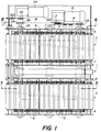
- the device illustrated in Figs. 1 to 4 is a straightening conveyor stack of P sheet material, including cardboard blanks, plus particularly corrugated cardboard, which has three parallel parts, a central part 1 formed by an endless pallet chain, and two side parts 2, 3 each formed by a series of rollers 4 mounted free around respective axes 5.
- the respective ends of these axes form the axis of articulation of links of four endless chains 6, 7 for side part 2 and 8, 9 for side part 3.
- the endless chains 6, 7 pass around two pairs of wheels 10, 11 of which only the pair of wheels 11 is visible in the drawing, the pair of wheels 10 being hidden by the chains 6, 7.
- the endless chains 8, 9 pass around two pairs of wheels 12 and 13.
- the pairs of wheels 10 and 12 are integral with a common shaft 20, while the pairs of wheels 11 and 13 are integral with a common shaft 21 (Fig. 4).
- FIG. 1 A mechanism for driving these chains 6-9 is illustrated by the Figs. 1 and 3.
- This mechanism comprises a geared motor 16 comprising a double output pinion 17, each of which is engaged with a chain without end 18, 19.
- the chain 18 is engaged with a wheel 22, integral with the shaft 20, while the chain 19 is engaged with a wheel 23 integral with the shaft 21.
- the two series of rollers 4 forming the two parts sides 2 and 3 of the straightening conveyor are kinematically integral of the same shafts 20, 21, driven by the drive mechanism which has just been described.
- Another drive mechanism of the central part 1, constituted by the pallet chain, comprises a second geared motor 24 a pinion integral with the output shaft 25 is engaged with a endless chain 26 intended to transmit the movement of this tree output 25 to a drive shaft 27 of the part's pallet chain central 1.
- the pallets of the chain at pallets have two thinned side parts 1b which rest on two sliding bearings 28, in the form of Teflon® strips, by example, or metal bars coated with this material, fixed on a part of frame B of this device, underlying the upper strand of this pallet chain.
- the level of the game central 1, which corresponds to the drive part of the conveyor rectifier is slightly higher than that of the side parts 2, 3, to ensure good contact with the stack of cardboard blanks P when this device is used in its mode of transport and not in that of rectifier, as well as allowing immobilization of the battery P when the device is used in its mode of rectification of the shape of this pile P.
- this device corresponding to the implementation work of the method according to the invention consists in placing this device at the following a transport section whose length is such that it risks deformation of the battery which could endanger its stability.
- the geared motor 24 is started and the central part raised 1, formed by the pallet chain drives the stack P by the part median of this stack which rests on this pallet chain.
- the parts of this stack located on either side of this central part 1 rest on the lateral parts 2 and 3 of the conveyor, including the free rollers 4 can rotate by the friction of the base of the P-stack.
- the part control unit 1 When all the stack P is on the straightening conveyor, the part control unit 1 is stopped and the gearmotor 16 is started to drive in translation the axes of the rollers 4 of the two parts lateral 2 and 3, these axes being integral with the chains 6, 7, respectively 8, 9 at their respective ends, in the same direction as that in advance of the P stack. These chains 6-9 rotate, while leaving the rollers 4 free to rotate on their respective axes 5.
- a photocell for example, or other means of appropriate detection can detect when the P battery is straightened.
- Figs. 5 and 6 illustrate another variant of the device which comes to be described, as well as a particular use of this variant.
- the transporter formed by the pallet chain of the part central 1 of Figs. 1 to 4 does not exist.
- friction pads 29, each associated with a bent lever 30, one of which end is hinged to this shoe 29 and the other end is engaged with the rod of a jack 31, while the bent part of this lever is articulated at frame B of the straightening conveyor device.
- chains 6, 7 of part 2 of the transporter and the chains 8, 9 of its part 3 are not not integral with the same drive shafts 20 and 21, but with shafts independent drive 20a, 21a, respectively 20b, 21b, only the shafts 20a, 20b being visible in FIG. 6.
- the trees 20a, 21a, on the one hand and the shafts 20b, 21b, on the other hand, are each secured to a mechanism independent training. Since these mechanisms are in all identical to mechanism 16-19 of the form of execution of Figs. 1-4, they are neither described nor represented again for this form of execution. The consequence of this independence of the two parts 2 and 3 of the carrier is to allow them to train at speeds different for the purpose that will be explained later.
- a stop mechanism illustrated in FIG. 5, is used to stop the P battery during the straightening operation.
- This mechanism is located in the middle part where the chain was pallets from part 1 in the previous embodiment.
- a stop 32 is integral with one end of a lever 33 articulated around an axis 34, integral with the frame B. The other end of this lever 33 is articulated to the rod 36 of a jack 35. In the position shown in solid lines on this Fig. 5, the stop 32 is brought by the lever 33 and the jack 35 in a position transverse to the path of the stack of cardboard blanks P.
- the jacks 31 apply the pads 29 against the respective upper strands of the two roller chains 4 of the lateral parts 2 and 3 of the conveyor device rectifier. Once these pads are applied against the rollers 4, the drive mechanisms of chains 6, 7, respectively 8, 9, are started at the same speed, driving these chains and the rollers 4 which are integral therewith. Since at the same time the pads 29 are pressed against the rollers 4 of the upper strands, these rollers are no longer free as before, but they are driven in rotation by their translational movement relative to the pads 29 that are applied against them. Therefore, the battery P is driven on the straightening device.
- the stop 32 is placed in the position illustrated in solid lines on Fig. 5, so that the battery P is stopped as soon as it encounters this stop 32.
- the roller chains 4 are immobilized and the pads 29 are retracted so that the free rollers can now rotate around of their respective axes of rotation 5.
- the roller chains are then restarted, but, since the rollers 4 have been released, they roll under the effect of their friction under the P pile, consecutive to displacement of their axes of rotation in translation in the direction in advance of stack P.
- the cardboard cutouts of the bottom of the P stack that had shifted relative to the rest of the stack are gradually brought back under the P pile, which thus regains its shape initial parallelepiped.
- the device according to FIGS. 5 and 6 can still have, in the central occupied part, in Figs. 1-4, by the pallet chain 1 and which is released in the variant of Figs. 5 and 6, a mechanism for changing the orientation of the batteries after having them straightened.
- This device comprises in its center a disc 37 with a vertical axis, integral with the rod of a jack 38.
- This disc can occupy two positions corresponding to two different levels, one located below that upper strands of roller chains 4, the other located slightly above the level of the upper strands of these roller chains 4.
- This upper level of disc 37 corresponds substantially to that of the strand upper of the pallet conveyor 1 of the embodiment of Figs. 1-4.
- Two centering bars 39, integral with two cylinder rods respective 40 are arranged on either side of the transporter, above the upper strands of the roller chains 4 and share and on the other side of the displacement path of stack P. These bars of centering are used to position the stack exactly in the center of the width of the straightening conveyor. This is necessary so that when the P stack is lifted by the disc 37, it is well balanced on it.
Landscapes
- Engineering & Computer Science (AREA)
- Mechanical Engineering (AREA)
- Stacking Of Articles And Auxiliary Devices (AREA)
- Battery Electrode And Active Subsutance (AREA)
Applications Claiming Priority (2)
| Application Number | Priority Date | Filing Date | Title |
|---|---|---|---|
| FR9802231 | 1998-02-19 | ||
| FR9802231A FR2774976B1 (fr) | 1998-02-19 | 1998-02-19 | Procede et dispositif pour redresser et/ou orienter une pile de materiau en feuilles deformee sur un transporteur a rouleaux |
Publications (2)
| Publication Number | Publication Date |
|---|---|
| EP0937671A1 true EP0937671A1 (de) | 1999-08-25 |
| EP0937671B1 EP0937671B1 (de) | 2002-07-17 |
Family
ID=9523314
Family Applications (1)
| Application Number | Title | Priority Date | Filing Date |
|---|---|---|---|
| EP99102440A Expired - Lifetime EP0937671B1 (de) | 1998-02-19 | 1999-02-09 | Verfahren und Vorrichtung zum Ausrichten eines unregelmässigen Stapels von Blattmaterial auf einer Rollenbahn |
Country Status (5)
| Country | Link |
|---|---|
| US (1) | US6045322A (de) |
| EP (1) | EP0937671B1 (de) |
| DE (1) | DE69902110T2 (de) |
| ES (1) | ES2180235T3 (de) |
| FR (1) | FR2774976B1 (de) |
Families Citing this family (2)
| Publication number | Priority date | Publication date | Assignee | Title |
|---|---|---|---|---|
| AU2003300045A1 (en) * | 2002-12-31 | 2004-07-29 | Shuttleworth, Inc. | Compression passing roller |
| CN103693489A (zh) * | 2013-12-03 | 2014-04-02 | 安徽嘉隆印刷有限公司 | 一种瓦楞纸下料台 |
Citations (2)
| Publication number | Priority date | Publication date | Assignee | Title |
|---|---|---|---|---|
| EP0066554A1 (de) * | 1981-05-20 | 1982-12-08 | Giampiero Giusti | Automatische Stapelvorrichtung für aus Blättern gebildete Stapel |
| DE4437915C1 (de) * | 1994-10-22 | 1996-05-15 | Kodak Ag | Vorrichtung zum kantengenauen Ausrichten von rechteckförmigen Papierblättern |
Family Cites Families (6)
| Publication number | Priority date | Publication date | Assignee | Title |
|---|---|---|---|---|
| US3225684A (en) * | 1964-09-02 | 1965-12-28 | Signode Corp | Machine for tying bundles |
| US3894627A (en) * | 1973-06-01 | 1975-07-15 | Fmc Corp | Conveyor for interspacing articles |
| AU511481B2 (en) * | 1976-12-14 | 1980-08-21 | Gerrard Wire Tying Machines Co. | Bundle squaring machine |
| US4142625A (en) * | 1977-12-02 | 1979-03-06 | Bourgeois Ronald D | Holding conveyor system |
| JPH0763783B2 (ja) * | 1988-07-07 | 1995-07-12 | アイダエンジニアリング株式会社 | ディスタックフィーダ |
| DE4000263A1 (de) * | 1990-01-03 | 1991-07-04 | System Gmbh | Vorrichtung zum richten von stapeln |
-
1998
- 1998-02-19 FR FR9802231A patent/FR2774976B1/fr not_active Expired - Fee Related
-
1999
- 1999-02-09 EP EP99102440A patent/EP0937671B1/de not_active Expired - Lifetime
- 1999-02-09 DE DE69902110T patent/DE69902110T2/de not_active Expired - Lifetime
- 1999-02-09 ES ES99102440T patent/ES2180235T3/es not_active Expired - Lifetime
- 1999-02-18 US US09/247,833 patent/US6045322A/en not_active Expired - Lifetime
Patent Citations (2)
| Publication number | Priority date | Publication date | Assignee | Title |
|---|---|---|---|---|
| EP0066554A1 (de) * | 1981-05-20 | 1982-12-08 | Giampiero Giusti | Automatische Stapelvorrichtung für aus Blättern gebildete Stapel |
| DE4437915C1 (de) * | 1994-10-22 | 1996-05-15 | Kodak Ag | Vorrichtung zum kantengenauen Ausrichten von rechteckförmigen Papierblättern |
Also Published As
| Publication number | Publication date |
|---|---|
| DE69902110T2 (de) | 2003-02-06 |
| US6045322A (en) | 2000-04-04 |
| EP0937671B1 (de) | 2002-07-17 |
| FR2774976B1 (fr) | 2000-04-14 |
| ES2180235T3 (es) | 2003-02-01 |
| FR2774976A1 (fr) | 1999-08-20 |
| DE69902110D1 (de) | 2002-08-22 |
Similar Documents
| Publication | Publication Date | Title |
|---|---|---|
| EP0881173B1 (de) | Rollen- oder Bandförderer zum Transportieren und Drehen von Artikeln niedriger spezifischer Masse | |
| EP0295203B1 (de) | Verfahren zum Verpacken eines Produkts und Vorrichtung zur Ausübung des Verfahrens | |
| EP1350748A2 (de) | Vorrichtung zum Wenden von Stapeln von Bogenmaterial | |
| EP1369213B1 (de) | Vorrichtung zur Trennung Befestigungspunkte, die gestapelte Kartonbogen verbinden | |
| FR2490602A1 (fr) | Systeme convoyeur rassemblant | |
| CH675404A5 (de) | ||
| EP0638496B1 (de) | Vorrichtung und Verfahren zum Einführen von blattformigem Material in eine Maschine | |
| FR2621025A1 (fr) | Appareil pour le pliage de materiaux en feuilles | |
| EP0983951A2 (de) | Korrigierende Vorrichtung mit Rollen oder Riemen zur seitlichen Ausrichtung, während der Verarbeitung, von Gegenständen, wie in einer Falt-Leimmaschine teilweise gefalteten Blättern oder Zuschnitten | |
| EP0244308B1 (de) | Maschine zum Aufnehmen und Stapeln von geschnittenen Bögen | |
| EP2704973B1 (de) | Vorrichtung zum stapeln von papierbögen oder dergleichen | |
| EP0937671B1 (de) | Verfahren und Vorrichtung zum Ausrichten eines unregelmässigen Stapels von Blattmaterial auf einer Rollenbahn | |
| EP1480800B1 (de) | Verfahren zum herstellen von platten aus hydraulischem bindemittel, fertigungsstrasse zur herstellung derartiger platten und vorrichtung zum prägen | |
| EP1335480B1 (de) | Verfahren und Vorrichtung zur Herstellung eines magnetischen Kreises einer elektrischen Maschine | |
| FR2584053A1 (fr) | Procede et dispositif de stockage temporaire d'articles imprimes se presentant selon une formation disposee a la maniere de tuiles etagees. | |
| FR2626264A3 (fr) | Appareil de distribution et d'enroulement de revetements de sol | |
| EP0267431B1 (de) | Einrichtung zum Stapeln von flachen Gegenständen | |
| EP1725393B1 (de) | Maschine und verfahren zur herstellung einer platte durch verwendung eines dorns | |
| FR2604654A1 (fr) | Machine pour la fabrication d'emballage de produits sous feuilles retractables | |
| EP4041539B1 (de) | Vorrichtung und verfahren zum bilden eines behälters durch falten | |
| FR2765554A1 (fr) | Machine permettant d'ouvrir des boites en carton de maniere automatisee | |
| WO2017178437A1 (fr) | Organe de prehension, barre de pinces et machine de traitement d'elements en forme de feuilles | |
| BE823679A (fr) | Machine a former des sacs en matiere plastique | |
| EP2374719B1 (de) | Anlage zum Aufbringen von Klebesegmenten auf durchlaufende Pakete | |
| FR2564778A1 (fr) | Machine pour la formation de piles de sacs en papier |
Legal Events
| Date | Code | Title | Description |
|---|---|---|---|
| PUAI | Public reference made under article 153(3) epc to a published international application that has entered the european phase |
Free format text: ORIGINAL CODE: 0009012 |
|
| 17P | Request for examination filed |
Effective date: 19990209 |
|
| AK | Designated contracting states |
Kind code of ref document: A1 Designated state(s): DE ES FR GB IT SE |
|
| AX | Request for extension of the european patent |
Free format text: AL;LT;LV;MK;RO;SI |
|
| AKX | Designation fees paid |
Free format text: DE ES FR GB IT SE |
|
| GRAG | Despatch of communication of intention to grant |
Free format text: ORIGINAL CODE: EPIDOS AGRA |
|
| 17Q | First examination report despatched |
Effective date: 20011106 |
|
| GRAG | Despatch of communication of intention to grant |
Free format text: ORIGINAL CODE: EPIDOS AGRA |
|
| GRAH | Despatch of communication of intention to grant a patent |
Free format text: ORIGINAL CODE: EPIDOS IGRA |
|
| GRAH | Despatch of communication of intention to grant a patent |
Free format text: ORIGINAL CODE: EPIDOS IGRA |
|
| GRAA | (expected) grant |
Free format text: ORIGINAL CODE: 0009210 |
|
| AK | Designated contracting states |
Kind code of ref document: B1 Designated state(s): DE ES FR GB IT SE |
|
| REG | Reference to a national code |
Ref country code: GB Ref legal event code: FG4D Free format text: NOT ENGLISH |
|
| REF | Corresponds to: |
Ref document number: 69902110 Country of ref document: DE Date of ref document: 20020822 |
|
| GBT | Gb: translation of ep patent filed (gb section 77(6)(a)/1977) |
Effective date: 20020813 |
|
| REG | Reference to a national code |
Ref country code: ES Ref legal event code: FG2A Ref document number: 2180235 Country of ref document: ES Kind code of ref document: T3 |
|
| PLBE | No opposition filed within time limit |
Free format text: ORIGINAL CODE: 0009261 |
|
| STAA | Information on the status of an ep patent application or granted ep patent |
Free format text: STATUS: NO OPPOSITION FILED WITHIN TIME LIMIT |
|
| 26N | No opposition filed |
Effective date: 20030422 |
|
| PGFP | Annual fee paid to national office [announced via postgrant information from national office to epo] |
Ref country code: GB Payment date: 20070130 Year of fee payment: 9 |
|
| PGFP | Annual fee paid to national office [announced via postgrant information from national office to epo] |
Ref country code: SE Payment date: 20070215 Year of fee payment: 9 |
|
| EUG | Se: european patent has lapsed | ||
| GBPC | Gb: european patent ceased through non-payment of renewal fee |
Effective date: 20080209 |
|
| PG25 | Lapsed in a contracting state [announced via postgrant information from national office to epo] |
Ref country code: SE Free format text: LAPSE BECAUSE OF NON-PAYMENT OF DUE FEES Effective date: 20080210 |
|
| PG25 | Lapsed in a contracting state [announced via postgrant information from national office to epo] |
Ref country code: GB Free format text: LAPSE BECAUSE OF NON-PAYMENT OF DUE FEES Effective date: 20080209 |
|
| REG | Reference to a national code |
Ref country code: FR Ref legal event code: PLFP Year of fee payment: 18 |
|
| REG | Reference to a national code |
Ref country code: FR Ref legal event code: PLFP Year of fee payment: 19 |
|
| PGFP | Annual fee paid to national office [announced via postgrant information from national office to epo] |
Ref country code: DE Payment date: 20170131 Year of fee payment: 19 Ref country code: FR Payment date: 20170202 Year of fee payment: 19 |
|
| PGFP | Annual fee paid to national office [announced via postgrant information from national office to epo] |
Ref country code: IT Payment date: 20170221 Year of fee payment: 19 Ref country code: ES Payment date: 20170112 Year of fee payment: 19 |
|
| REG | Reference to a national code |
Ref country code: DE Ref legal event code: R119 Ref document number: 69902110 Country of ref document: DE |
|
| REG | Reference to a national code |
Ref country code: FR Ref legal event code: ST Effective date: 20181031 |
|
| PG25 | Lapsed in a contracting state [announced via postgrant information from national office to epo] |
Ref country code: DE Free format text: LAPSE BECAUSE OF NON-PAYMENT OF DUE FEES Effective date: 20180901 |
|
| PG25 | Lapsed in a contracting state [announced via postgrant information from national office to epo] |
Ref country code: IT Free format text: LAPSE BECAUSE OF NON-PAYMENT OF DUE FEES Effective date: 20180209 Ref country code: FR Free format text: LAPSE BECAUSE OF NON-PAYMENT OF DUE FEES Effective date: 20180228 |
|
| REG | Reference to a national code |
Ref country code: ES Ref legal event code: FD2A Effective date: 20190801 |
|
| PG25 | Lapsed in a contracting state [announced via postgrant information from national office to epo] |
Ref country code: ES Free format text: LAPSE BECAUSE OF NON-PAYMENT OF DUE FEES Effective date: 20180210 |