EP0937592B1 - Unterer Haken für Dreipunktgestänge - Google Patents
Unterer Haken für Dreipunktgestänge Download PDFInfo
- Publication number
- EP0937592B1 EP0937592B1 EP99201031A EP99201031A EP0937592B1 EP 0937592 B1 EP0937592 B1 EP 0937592B1 EP 99201031 A EP99201031 A EP 99201031A EP 99201031 A EP99201031 A EP 99201031A EP 0937592 B1 EP0937592 B1 EP 0937592B1
- Authority
- EP
- European Patent Office
- Prior art keywords
- hook
- blocking device
- opening
- lever
- control lever
- Prior art date
- Legal status (The legal status is an assumption and is not a legal conclusion. Google has not performed a legal analysis and makes no representation as to the accuracy of the status listed.)
- Expired - Lifetime
Links
Images
Classifications
-
- B—PERFORMING OPERATIONS; TRANSPORTING
- B60—VEHICLES IN GENERAL
- B60D—VEHICLE CONNECTIONS
- B60D1/00—Traction couplings; Hitches; Draw-gear; Towing devices
- B60D1/14—Draw-gear or towing devices characterised by their type
- B60D1/141—Arrangements or frames adapted to allow the connection of trailers to tractor three-point hitches
-
- A—HUMAN NECESSITIES
- A01—AGRICULTURE; FORESTRY; ANIMAL HUSBANDRY; HUNTING; TRAPPING; FISHING
- A01B—SOIL WORKING IN AGRICULTURE OR FORESTRY; PARTS, DETAILS, OR ACCESSORIES OF AGRICULTURAL MACHINES OR IMPLEMENTS, IN GENERAL
- A01B59/00—Devices specially adapted for connection between animals or tractors and agricultural machines or implements
- A01B59/002—Details, component parts
- A01B59/006—Latched hooks
-
- B—PERFORMING OPERATIONS; TRANSPORTING
- B60—VEHICLES IN GENERAL
- B60D—VEHICLE CONNECTIONS
- B60D1/00—Traction couplings; Hitches; Draw-gear; Towing devices
- B60D1/01—Traction couplings or hitches characterised by their type
- B60D1/04—Hook or hook-and-hasp couplings
Definitions
- the present invention concerns a lower hook for three-point linkages, in particular for the coupling of an implement to agricultural machinery, of the type comprising:
- a hook of the known type indicated above is described in the patent EP-0523332.
- the purpose of this invention is to propose a series of significant improvements which allow better control, during design and manufacture of the hook, of the forces necessary to open and close the blocking device and to clamp it in the open position, and which make the hook easier to use also under difficult conditions.
- the purpose of the invention is to provide a lower hook which can be manufactured easily and cheaply, is simple to use and maintain and is extremely reliable even for prolonged use under difficult conditions.
- a hook of the type mentioned in the preamble of the present description characterised in that the control lever comprises a shaped portion which, in the clamped open position of the hook only, interferes with a corresponding shaped portion provided on the main body, the interference between the two shaped portions being by itself sufficient to contrast the return action of the resilient means so as to hold the blocking device in the retracted position.
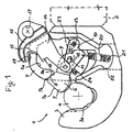
- reference numeral 1 globally indicates a lower hook for three-point linkages, of the type used on agricultural machinery, mounted at the end of a lower bar 2.
- the hook 1 comprises a hook-shaped portion 3 which defines a recess 3a shaped in such a way as to house a coupling sphere 4 of an implement which can be coupled to the agricultural machinery, and a main hollow body 5.
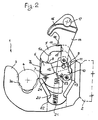
- a blocking device 6 is mounted in the cavity 5a of the main body 5 and is movable from an extracted position, shown in figure 1, to a retracted position, shown in figure 2.
- a head portion 7 of the blocking device 6 protrudes outside the main body 5 towards the hook portion 3 through a slit 8 so as to block the coupling sphere housed in the recess 3a.
- the head 7 of the blocking device retracts towards the slit 8 inside the main body 5, freeing the recess 3a.
- the blocking device 6 On the opposite side of the head 7, the blocking device 6 comprises a body 9 hinged to a pivoting lever 10 by means of a peg-slot coupling.
- a peg 11 is fixed to the body 9 of the blocking device and engages in a slot 12 provided in the lever 10, which is in turn hinged to the main body of the hook, within the cavity 5a, by means of a pin 13.
- the coupling between the blocking device 6 and the lever 10 is a combined sliding/rotating mechanism and can also be achieved by positioning the peg on the lever 10 and providing the blocking device 6 with the slot, or also by other coupling means known to the experts in the field, such as for example guides, recessed sections and the like.
- a control lever 14 is hinged to the end of the lever 10 and extends outside the main body 5 of the hook through an upper opening 15, ending in a larger upper portion 16 which covers the opening 15 when the hook is in the closed position and the blocking device is in the extracted position.
- the upper part 16 has a hole 17 for the coupling of known types of pulling means.
- the front part of the control lever 14 comprises a clamping tooth 18 which engages with a correspondingly shaped portion 19 provided on the outside of the main body of the hook, close to and in front of the opening 15, so as to block the hook in the open position, as shown in figure 2.
- the shaped part 19 may be a cavity achieved by casting, by pressing, by subsequent mechanical machining, or may simply created by inserting a cross pin in the body of the hook or by other similar means.
- a resilient element 20 is attached, particularly but not necessarily a helical spring, the other end of which is attached to a peg 21 or to a generic projection, positioned in correspondence with an opening 22 which communicates with the cavity 5a of the main body.
- the opening 22 may of course be a different shape to the one shown and, in particular, may be replaced or associated with a lateral hole or opening provided in one of the two side walls of the body of the hook.
- An alternative to the preferred embodiment may have a lateral hole provided in one of the side walls of the hook, the axis of which substantially coincides with the axis of the peg 21, thus allowing access to the peg during assembly, inspection and maintenance of the spring 20.
- the helical spring 20 can be replaced by a torsion or flat spring which urges against a portion of the lever 10.
- the resilient element 20 can also act directly on the blocking device 6.
- the inner wall of the main body 5 is shaped so as to define an abutment element 23 positioned close to the pin 13 to which the lever 10 is hinged, against which a portion of the body 9 of the blocking device 6 presses when the latter is in the extracted position shown in figure 1.
- a guide pin 24 is fitted inside the body of the hook to guide and support the head 7 of the blocking device 6 when this is in the retracted position shown in figure 2.
- the blocking device 6 When the hook 1 is in the closed position shown in figure 1, the blocking device 6 is in the extracted position in such a way that its head 7 engages at least partially with the recess 3a to clamp a coupling sphere 4 which is housed in the recess, preventing it from slipping out.
- no pressure of the coupling sphere 4 on the blocking device 6 can move it from the extracted position because the upper part 7b of the head 7 is in abutment with the upper edge 8a of the slit 8, while the body 9 presses against the abutment element 23, being also partially thereunder with respect to a possible rotation of the blocking device around the contact point between the head 7 and the upper edge 8a of the slit 8.
- the hook can be opened easily by applying traction to the larger portion 16, and thus on the control lever 14, so as to extract the latter from the cavity 5a.
- the control lever 14 rotatably pulls the lever 10 against the return action of the spring 20. As it rotates, the lever 10 pulls the blocking device 6 inside the cavity 5a towards the retracted position shown in figure 2.
- the hook can be clamped permanently in this position by imparting a rotation to the control lever 14 so as to move the clamping tooth 18 above the upper wall of the main body 5, housing it in the cavity 19.
- the presence of the cavity 19 is nevertheless preferable for greater clamping security.
- the mechanism of the hook described above makes it possible to insert a coupling sphere 4 in the recess 3a without it being necessary to manoeuvre the control lever 14.
- the pressure exerted by a coupling sphere 4 on the front portion 7a of the head 7 of the blocking device in the extracted position causes the latter to rotate due to the reaction with the peg 24, whereby the lever 10 is forced rotatably against the action of the spring 20, allowing the blocking device to retract inside the cavity 5a.
- the rotation of the lever 10 also raises the control lever 14 which, however, due to its weight, remains resting against the lower edge of the opening 15, keeping the clamping tooth 18 away from the edge on which the cavity 19 is located, thus preventing involuntary clamping of the hook in the open position.
- the position of the peg 21 for the attachment of the spring, the linking position of the spring to the lever 10, the shape of the lever 10 and its hinging points for the blocking device 6 and for the control lever 14 can be varied during design to achieve even very fine adjustments of the functioning characteristics of the opening and closing mechanism of the hook and the forces necessary for these operations and for the clamping and unclamping operations.
- the lever arm of the force exerted by the spring 20 on the lever 10 varies in accordance with the rotation angle of the lever itself.
- this lever arm has a lower value when the hook is in the closed position, while it increases progressively until the hook is completely open, decreasing slightly when the control lever 14 is completely extracted to allow the tooth 18 to engage with the cavity 19.
Landscapes
- Engineering & Computer Science (AREA)
- Mechanical Engineering (AREA)
- Life Sciences & Earth Sciences (AREA)
- Transportation (AREA)
- Environmental Sciences (AREA)
- Soil Sciences (AREA)
- Zoology (AREA)
- Hooks, Suction Cups, And Attachment By Adhesive Means (AREA)
- Holders For Apparel And Elements Relating To Apparel (AREA)
- Fertilizing (AREA)
- Pivots And Pivotal Connections (AREA)
- Agricultural Machines (AREA)
- Slide Fasteners, Snap Fasteners, And Hook Fasteners (AREA)
Claims (8)
- Unterer Haken für ein Dreipunktgestänge, insbesondere zur Kupplung eines Werkzeuges an eine landwirtschaftliche Gerätschaft, umfassend:dadurch gekennzeichnet, daß der Betätigungshebel (14) einen geformten Abschnitt (18) umfaßt, der nur in der klemmgesicherten offenen Stellung des Hakens mit einem an dem Hauptteil (5) vorgesehenen entsprechend geformten Abschnitt (19) zusammenwirkt, wobei die Zusammenwirkung der beiden geformten Abschnitte (18, 19) für sich ausreicht, um die Rückstellkraft der elastischen Mittel (20) zu überwinden, so daß die Verriegelungsvorrichtung (6) in der eingezogenen Stellung gehalten wird.einen Hautpteil, der einen hakenförmigen Abschnitt (3) aufweist, der eine Vertiefung (3a) zur teilweisen Aufnahme einer Kupplungskugel (4) eines Werkzeuges bei der Benutzung bildet,eine Verriegelungsvorrichtung (6), die zumindest teilweise in einem Innenraum (5a) des Hauptteiles des Hakens aufgenommen ist, aus dem sie durch eine erste Öffnung (8) herausragen kann, wobei die Verriegelungsvorrichtung wahlweise von einer den Haken schließenden ausgefahrenen Stellung in eine den Haken freigebende eingezogene offene Stellung des Hakens bewegbar ist,einen Betätigungshebel (14), der in dem Innenraum des Hauptteiles aufgenommen ist und zumindest teilweise aus einer zweiten Öffnung herausragt und der zur Steuerung des Öffnens des Hakens durch eine Bewegung der Verriegelungsvorrichtung (6) von der ausgefahrenen Stellung in die eingezogene Stellung betätigbar ist, undelastische Mittel (20), die eine elastische Rückstellkraft ausüben, um die Verriegelungsvorrichtung (6) von der eingezogenen Stellung in die ausgefahrene Stellung zurückzuversetzen und in dieser Stellung festzuhalten,
- Unterer Haken für ein Dreipunktgestänge nach Anspruch 1, dadurch gekennzeichnet, daß der geformte Abschnitt des Betätigungshebels (14) ein Klemmzahn (18) ist, der in dem Innenraum (5a) des Hakens aufgenommen ist, wenn sich dieser in der geschlossenen Stellung befindet, und aus der zweiten Öffnung (15) des Hakens herauskommt, wenn sich dieser in der offenen Stellung befindet, so daß er durch eine Drehung des Betätigungshebels (14) gewünschtenfalls mit dem entsprechend geformten Abschnitt (19) des Hakenkörpers in Eingriff bringbar ist.
- Unterer Haken für ein Dreipunktgestänge nach Anspruch 2, dadurch gekennzeichnet, daß der Klemmzahn (18) auf den hakenförmigen Abschnitt (3) des Hakens hin gerichtet ist und der entsprechend geformte Abschnitt des Hakenkörpers eine Vertiefung (19) umfaßt, die in der Außenwand des Hakens nahe dem Rand der zweiten Öffnung (15) vorgesehen ist.
- Unterer Haken für ein Dreipunktgestänge nach Anspruch 1, dadurch gekennzeichnet, daß der Haken auch ein Hebelelement (10) umfaßt, das in dem Innenraum (5a) des Hauptteiles aufgenommen ist, und die Verriegelungsvorrichtung (6) und der Betätigungshebel (14) an Drehpunkten mit dem Hebelelement (10) verbunden sind, wobei die elastischen Mittel (20) die elastische Rückstellkraft auf das Hebelelement (10) ausüben.
- Unterer Haken für ein Dreipunktgestänge nach Anspruch 4,
dadurch gekennzeichnet, daß die Drehpunkte der Verriegelungsvorrichtung (6) und des Betätigungshebels (14) auf dem Hebelelement (10) voneinander beabstandet sind und auch von dem Punkt beabstandet sind, an dem die von den elastischen Mitteln (20) ausgeübte Rückstellkraft angreift. - Unterer Haken für ein Dreipunktgestänge nach Anspruch 1, dadurch gekennzeichnet, daß die elastischen Mittel eine Spiralfeder umfassen, die mit einem Ende an dem Hebelelement und mit dem anderen Ende mit einer Öffnung (22) in dem Hauptteil ausgerichtet an einem Zapfen oder Vorsprung befestigt ist, der an dem Hakenkörper unterhalb des Hebelelements angeordnet ist.
- Unterer Haken für ein Dreipunktgestänge nach Anspruch 1, dadurch gekennzeichnet, daß der Betätigungshebel (14) in dem Innenraum (5a) des Hauptteiles aufgenommen ist und die zumindest teilweise aus einer zweiten Öffnung (15) herausragt, die zweite Öffnung (15) von der ersten Öffnung (8), aus der die Verriegelungsvorrichtung (6) herausragt, verschieden ist, wobei ein äußerer Abschnitt (16) des Betätigungshebels als Abdeckung für die zweite Öffnung (15) wirkt, wenn sich der Haken in der geschlossenen Stellung befindet.
- Landwirtschaftliche Gerätschaft umfassend ein Dreipunktgestänge mit zwei unteren Trägern und einem oberen Träger, wobei die Enden der unteren Träger jeweils mit einem unteren Haken gemäß einem beliebigen der vorhergehenden Ansprüche ausgestattet sind.
Applications Claiming Priority (3)
| Application Number | Priority Date | Filing Date | Title |
|---|---|---|---|
| IT96BO000685A IT1287615B1 (it) | 1996-12-24 | 1996-12-24 | Gancio inferiore per attacchi a tre punti |
| ITBO960685 | 1996-12-24 | ||
| EP97120930A EP0850789B1 (de) | 1996-12-24 | 1997-11-28 | Unterer Haken für Dreipunktgestänge |
Related Parent Applications (1)
| Application Number | Title | Priority Date | Filing Date |
|---|---|---|---|
| EP97120930A Division EP0850789B1 (de) | 1996-12-24 | 1997-11-28 | Unterer Haken für Dreipunktgestänge |
Publications (3)
| Publication Number | Publication Date |
|---|---|
| EP0937592A2 EP0937592A2 (de) | 1999-08-25 |
| EP0937592A3 EP0937592A3 (de) | 1999-11-17 |
| EP0937592B1 true EP0937592B1 (de) | 2002-06-05 |
Family
ID=11341814
Family Applications (2)
| Application Number | Title | Priority Date | Filing Date |
|---|---|---|---|
| EP97120930A Expired - Lifetime EP0850789B1 (de) | 1996-12-24 | 1997-11-28 | Unterer Haken für Dreipunktgestänge |
| EP99201031A Expired - Lifetime EP0937592B1 (de) | 1996-12-24 | 1997-11-28 | Unterer Haken für Dreipunktgestänge |
Family Applications Before (1)
| Application Number | Title | Priority Date | Filing Date |
|---|---|---|---|
| EP97120930A Expired - Lifetime EP0850789B1 (de) | 1996-12-24 | 1997-11-28 | Unterer Haken für Dreipunktgestänge |
Country Status (5)
| Country | Link |
|---|---|
| EP (2) | EP0850789B1 (de) |
| AT (2) | ATE218451T1 (de) |
| DE (2) | DE69700300T2 (de) |
| ES (2) | ES2178343T3 (de) |
| IT (1) | IT1287615B1 (de) |
Cited By (1)
| Publication number | Priority date | Publication date | Assignee | Title |
|---|---|---|---|---|
| US7225883B2 (en) | 2004-06-08 | 2007-06-05 | Kabushiki Kaisha Delica | Device for coupling implement to agricultural tractor |
Families Citing this family (7)
| Publication number | Priority date | Publication date | Assignee | Title |
|---|---|---|---|---|
| FI106522B (fi) * | 1998-08-21 | 2001-02-28 | Paavo Antero Viikki | Erityisesti traktorin kolmipistekiinnityksen vetovarren kytkinkoura |
| FI5615U1 (fi) * | 2002-08-15 | 2002-11-27 | Paavo Viikki | Erityisesti traktorin kolmipistekiinnityksen vetovarren kytkinkoura |
| IT1399307B1 (it) | 2009-09-15 | 2013-04-16 | Cbm Spa | Coppia di ganci per attacco a tre punti |
| JP6643417B2 (ja) * | 2018-08-02 | 2020-02-12 | Hapsモバイル株式会社 | システム、制御装置及び軽航空機 |
| ES2995585T3 (en) | 2020-04-06 | 2025-02-10 | Aero Velocity Inc | Flying vehicle systems and methods |
| EP4185097A4 (de) * | 2020-05-14 | 2024-11-06 | Uniparts India Ltd. | Unterer verbindungshaken |
| DE102024106098A1 (de) * | 2024-03-02 | 2025-09-04 | Jost-Werke Deutschland Gmbh | Schnellkupplungshaken mit erleichterter Bedienung |
Family Cites Families (3)
| Publication number | Priority date | Publication date | Assignee | Title |
|---|---|---|---|---|
| GB113755A (en) * | 1917-09-10 | 1918-03-07 | James Richard Irwin | Improvements in and relating to Locking and Releasing Devices. |
| JPS6397410A (ja) * | 1986-10-13 | 1988-04-28 | Nanmoto Kk | 連結フツク |
| IT1253787B (it) * | 1991-07-10 | 1995-08-23 | Cbm Spa | Meccanismo di movimentazione del chiavistello di bloccaggio automaticoe sblocco comandato delle rotule di attrezzi portati e semiportati da macchine agricole, per ganci inferiori di attacchi a tre punti. |
-
1996
- 1996-12-24 IT IT96BO000685A patent/IT1287615B1/it active IP Right Grant
-
1997
- 1997-11-28 ES ES99201031T patent/ES2178343T3/es not_active Expired - Lifetime
- 1997-11-28 DE DE69700300T patent/DE69700300T2/de not_active Expired - Lifetime
- 1997-11-28 DE DE69713130T patent/DE69713130T2/de not_active Expired - Lifetime
- 1997-11-28 AT AT99201031T patent/ATE218451T1/de active
- 1997-11-28 ES ES97120930T patent/ES2134668T3/es not_active Expired - Lifetime
- 1997-11-28 EP EP97120930A patent/EP0850789B1/de not_active Expired - Lifetime
- 1997-11-28 AT AT97120930T patent/ATE181703T1/de active
- 1997-11-28 EP EP99201031A patent/EP0937592B1/de not_active Expired - Lifetime
Cited By (1)
| Publication number | Priority date | Publication date | Assignee | Title |
|---|---|---|---|---|
| US7225883B2 (en) | 2004-06-08 | 2007-06-05 | Kabushiki Kaisha Delica | Device for coupling implement to agricultural tractor |
Also Published As
| Publication number | Publication date |
|---|---|
| DE69713130D1 (de) | 2002-07-11 |
| IT1287615B1 (it) | 1998-08-06 |
| DE69700300T2 (de) | 1999-11-18 |
| EP0850789A1 (de) | 1998-07-01 |
| EP0850789B1 (de) | 1999-06-30 |
| ES2134668T3 (es) | 1999-10-01 |
| EP0937592A2 (de) | 1999-08-25 |
| DE69700300D1 (de) | 1999-08-05 |
| EP0937592A3 (de) | 1999-11-17 |
| ES2178343T3 (es) | 2002-12-16 |
| ITBO960685A1 (it) | 1998-06-24 |
| ATE218451T1 (de) | 2002-06-15 |
| ATE181703T1 (de) | 1999-07-15 |
| ITBO960685A0 (it) | 1996-12-24 |
| DE69713130T2 (de) | 2003-02-13 |
Similar Documents
| Publication | Publication Date | Title |
|---|---|---|
| EP0400534B1 (de) | Vorrichtung für die Schwenk-Kipp-Öffnung eines Fensters oder Türfensters | |
| US5180198A (en) | Motor driven lock device for trunk lid and the like | |
| EP0937592B1 (de) | Unterer Haken für Dreipunktgestänge | |
| US6449904B1 (en) | Closure sequence control mechanism for a pair of doors | |
| US5611227A (en) | Handleset with thumb piece and rack | |
| HU205191B (en) | Joint structure for doors and windows particularly furniture-doors | |
| US8596693B2 (en) | Locking unit | |
| GB2342334A (en) | Fifth wheel coupling | |
| US5513510A (en) | Handleset with thumb piece and rack | |
| EP1403452A1 (de) | Schloss für Sektionaltore | |
| US5311644A (en) | Hinge having stop notches for a door, particularly a car door | |
| JP3976100B2 (ja) | 電気式窓開閉装置と動作要素を連結するための連結装置、ならびに該連結装置と併用される電気式操作装置 | |
| PL104558B1 (pl) | Hak sprzegowy,zwlaszcza do trojpunktowego zawieszenia narzedzi rolniczych na ciagniku | |
| GB1561194A (en) | Locking mechanism for engaging a movable side as tail board of a vehicle | |
| US5725234A (en) | Ball-type coupler for trailers and the like | |
| US6067823A (en) | Lock mechanism device | |
| EP0027746B1 (de) | Vorrichtung zum Verriegeln und Öffnen einer Fahrzeugtür | |
| US6152509A (en) | Coupling element | |
| US4645259A (en) | Actuator for an openable vehicle roof | |
| US5560079A (en) | Door closers | |
| EP0965717B1 (de) | Vorrichtung zum schnellen Lösen von Torflügeln | |
| EP0812711B1 (de) | Automatische Anhängervorrichtung für Fahrzeuge, insbesondere für Landwirtschaftsfahrzeuge | |
| HU223550B1 (hu) | Zárószerkezet, különösen zár ablakszárnyba vagy hasonlóba való beépítésre | |
| EP0783842B1 (de) | Vorrichtung zur Verriegelung des Visiers eines Helms für Motorradfahrer und dergleichen | |
| AU2021250932B2 (en) | Noise Dampener For A Vehicle Hitch |
Legal Events
| Date | Code | Title | Description |
|---|---|---|---|
| PUAI | Public reference made under article 153(3) epc to a published international application that has entered the european phase |
Free format text: ORIGINAL CODE: 0009012 |
|
| AC | Divisional application: reference to earlier application |
Ref document number: 850789 Country of ref document: EP |
|
| AK | Designated contracting states |
Kind code of ref document: A2 Designated state(s): AT DE ES FR GB |
|
| PUAL | Search report despatched |
Free format text: ORIGINAL CODE: 0009013 |
|
| AK | Designated contracting states |
Kind code of ref document: A3 Designated state(s): AT DE ES FR GB |
|
| RIC1 | Information provided on ipc code assigned before grant |
Free format text: 6B 60D 1/04 A, 6A 01B 59/043 B |
|
| 17P | Request for examination filed |
Effective date: 19991008 |
|
| GRAG | Despatch of communication of intention to grant |
Free format text: ORIGINAL CODE: EPIDOS AGRA |
|
| 17Q | First examination report despatched |
Effective date: 20010302 |
|
| GRAG | Despatch of communication of intention to grant |
Free format text: ORIGINAL CODE: EPIDOS AGRA |
|
| GRAH | Despatch of communication of intention to grant a patent |
Free format text: ORIGINAL CODE: EPIDOS IGRA |
|
| GRAH | Despatch of communication of intention to grant a patent |
Free format text: ORIGINAL CODE: EPIDOS IGRA |
|
| GRAA | (expected) grant |
Free format text: ORIGINAL CODE: 0009210 |
|
| AC | Divisional application: reference to earlier application |
Ref document number: 850789 Country of ref document: EP |
|
| AK | Designated contracting states |
Kind code of ref document: B1 Designated state(s): AT DE ES FR GB |
|
| REF | Corresponds to: |
Ref document number: 218451 Country of ref document: AT Date of ref document: 20020615 Kind code of ref document: T |
|
| REG | Reference to a national code |
Ref country code: GB Ref legal event code: FG4D |
|
| REF | Corresponds to: |
Ref document number: 69713130 Country of ref document: DE Date of ref document: 20020711 |
|
| ET | Fr: translation filed | ||
| REG | Reference to a national code |
Ref country code: ES Ref legal event code: FG2A Ref document number: 2178343 Country of ref document: ES Kind code of ref document: T3 |
|
| PLBE | No opposition filed within time limit |
Free format text: ORIGINAL CODE: 0009261 |
|
| STAA | Information on the status of an ep patent application or granted ep patent |
Free format text: STATUS: NO OPPOSITION FILED WITHIN TIME LIMIT |
|
| 26N | No opposition filed |
Effective date: 20030306 |
|
| REG | Reference to a national code |
Ref country code: FR Ref legal event code: PLFP Year of fee payment: 19 |
|
| PGFP | Annual fee paid to national office [announced via postgrant information from national office to epo] |
Ref country code: GB Payment date: 20151127 Year of fee payment: 19 Ref country code: DE Payment date: 20151127 Year of fee payment: 19 |
|
| PGFP | Annual fee paid to national office [announced via postgrant information from national office to epo] |
Ref country code: AT Payment date: 20151103 Year of fee payment: 19 Ref country code: FR Payment date: 20151117 Year of fee payment: 19 Ref country code: ES Payment date: 20151126 Year of fee payment: 19 |
|
| REG | Reference to a national code |
Ref country code: DE Ref legal event code: R119 Ref document number: 69713130 Country of ref document: DE |
|
| REG | Reference to a national code |
Ref country code: AT Ref legal event code: MM01 Ref document number: 218451 Country of ref document: AT Kind code of ref document: T Effective date: 20161128 |
|
| GBPC | Gb: european patent ceased through non-payment of renewal fee |
Effective date: 20161128 |
|
| REG | Reference to a national code |
Ref country code: FR Ref legal event code: ST Effective date: 20170731 |
|
| PG25 | Lapsed in a contracting state [announced via postgrant information from national office to epo] |
Ref country code: AT Free format text: LAPSE BECAUSE OF NON-PAYMENT OF DUE FEES Effective date: 20161128 |
|
| PG25 | Lapsed in a contracting state [announced via postgrant information from national office to epo] |
Ref country code: FR Free format text: LAPSE BECAUSE OF NON-PAYMENT OF DUE FEES Effective date: 20161130 |
|
| PG25 | Lapsed in a contracting state [announced via postgrant information from national office to epo] |
Ref country code: GB Free format text: LAPSE BECAUSE OF NON-PAYMENT OF DUE FEES Effective date: 20161128 Ref country code: DE Free format text: LAPSE BECAUSE OF NON-PAYMENT OF DUE FEES Effective date: 20170601 |
|
| REG | Reference to a national code |
Ref country code: ES Ref legal event code: FD2A Effective date: 20180507 |
|
| PG25 | Lapsed in a contracting state [announced via postgrant information from national office to epo] |
Ref country code: ES Free format text: LAPSE BECAUSE OF FAILURE TO SUBMIT A TRANSLATION OF THE DESCRIPTION OR TO PAY THE FEE WITHIN THE PRESCRIBED TIME-LIMIT Effective date: 20020605 |
|
| PG25 | Lapsed in a contracting state [announced via postgrant information from national office to epo] |
Ref country code: ES Free format text: LAPSE BECAUSE OF FAILURE TO SUBMIT A TRANSLATION OF THE DESCRIPTION OR TO PAY THE FEE WITHIN THE PRESCRIBED TIME-LIMIT Effective date: 20161129 |
|
| RIC2 | Information provided on ipc code assigned after grant |
Ipc: B60D 1/04 20060101AFI19990928BHEP Ipc: A01B 59/043 20060101ALI19990928BHEP |