EP0937502A2 - Verfahren und Vorrichtung zur Behandlung von Musterplatten - Google Patents
Verfahren und Vorrichtung zur Behandlung von Musterplatten Download PDFInfo
- Publication number
- EP0937502A2 EP0937502A2 EP98660141A EP98660141A EP0937502A2 EP 0937502 A2 EP0937502 A2 EP 0937502A2 EP 98660141 A EP98660141 A EP 98660141A EP 98660141 A EP98660141 A EP 98660141A EP 0937502 A2 EP0937502 A2 EP 0937502A2
- Authority
- EP
- European Patent Office
- Prior art keywords
- sample
- liquid
- sample plate
- plate
- wells
- Prior art date
- Legal status (The legal status is an assumption and is not a legal conclusion. Google has not performed a legal analysis and makes no representation as to the accuracy of the status listed.)
- Granted
Links
Images


Classifications
-
- B—PERFORMING OPERATIONS; TRANSPORTING
- B01—PHYSICAL OR CHEMICAL PROCESSES OR APPARATUS IN GENERAL
- B01L—CHEMICAL OR PHYSICAL LABORATORY APPARATUS FOR GENERAL USE
- B01L3/00—Containers or dishes for laboratory use, e.g. laboratory glassware; Droppers
- B01L3/02—Burettes; Pipettes
- B01L3/0203—Burettes, i.e. for withdrawing and redistributing liquids through different conduits
-
- B—PERFORMING OPERATIONS; TRANSPORTING
- B01—PHYSICAL OR CHEMICAL PROCESSES OR APPARATUS IN GENERAL
- B01L—CHEMICAL OR PHYSICAL LABORATORY APPARATUS FOR GENERAL USE
- B01L13/00—Cleaning or rinsing apparatus
- B01L13/02—Cleaning or rinsing apparatus for receptacle or instruments
-
- B—PERFORMING OPERATIONS; TRANSPORTING
- B01—PHYSICAL OR CHEMICAL PROCESSES OR APPARATUS IN GENERAL
- B01L—CHEMICAL OR PHYSICAL LABORATORY APPARATUS FOR GENERAL USE
- B01L3/00—Containers or dishes for laboratory use, e.g. laboratory glassware; Droppers
- B01L3/02—Burettes; Pipettes
- B01L3/0289—Apparatus for withdrawing or distributing predetermined quantities of fluid
- B01L3/0293—Apparatus for withdrawing or distributing predetermined quantities of fluid for liquids
-
- G—PHYSICS
- G01—MEASURING; TESTING
- G01N—INVESTIGATING OR ANALYSING MATERIALS BY DETERMINING THEIR CHEMICAL OR PHYSICAL PROPERTIES
- G01N35/00—Automatic analysis not limited to methods or materials provided for in any single one of groups G01N1/00 - G01N33/00; Handling materials therefor
- G01N35/02—Automatic analysis not limited to methods or materials provided for in any single one of groups G01N1/00 - G01N33/00; Handling materials therefor using a plurality of sample containers moved by a conveyor system past one or more treatment or analysis stations
- G01N35/028—Automatic analysis not limited to methods or materials provided for in any single one of groups G01N1/00 - G01N33/00; Handling materials therefor using a plurality of sample containers moved by a conveyor system past one or more treatment or analysis stations having reaction cells in the form of microtitration plates
-
- B—PERFORMING OPERATIONS; TRANSPORTING
- B01—PHYSICAL OR CHEMICAL PROCESSES OR APPARATUS IN GENERAL
- B01L—CHEMICAL OR PHYSICAL LABORATORY APPARATUS FOR GENERAL USE
- B01L2200/00—Solutions for specific problems relating to chemical or physical laboratory apparatus
- B01L2200/06—Fluid handling related problems
- B01L2200/0684—Venting, avoiding backpressure, avoid gas bubbles
-
- B—PERFORMING OPERATIONS; TRANSPORTING
- B01—PHYSICAL OR CHEMICAL PROCESSES OR APPARATUS IN GENERAL
- B01L—CHEMICAL OR PHYSICAL LABORATORY APPARATUS FOR GENERAL USE
- B01L2300/00—Additional constructional details
- B01L2300/08—Geometry, shape and general structure
- B01L2300/0809—Geometry, shape and general structure rectangular shaped
- B01L2300/0829—Multi-well plates; Microtitration plates
-
- B—PERFORMING OPERATIONS; TRANSPORTING
- B01—PHYSICAL OR CHEMICAL PROCESSES OR APPARATUS IN GENERAL
- B01L—CHEMICAL OR PHYSICAL LABORATORY APPARATUS FOR GENERAL USE
- B01L2400/00—Moving or stopping fluids
- B01L2400/04—Moving fluids with specific forces or mechanical means
- B01L2400/0403—Moving fluids with specific forces or mechanical means specific forces
- B01L2400/0409—Moving fluids with specific forces or mechanical means specific forces centrifugal forces
-
- B—PERFORMING OPERATIONS; TRANSPORTING
- B01—PHYSICAL OR CHEMICAL PROCESSES OR APPARATUS IN GENERAL
- B01L—CHEMICAL OR PHYSICAL LABORATORY APPARATUS FOR GENERAL USE
- B01L3/00—Containers or dishes for laboratory use, e.g. laboratory glassware; Droppers
- B01L3/50—Containers for the purpose of retaining a material to be analysed, e.g. test tubes
- B01L3/508—Containers for the purpose of retaining a material to be analysed, e.g. test tubes rigid containers not provided for above
- B01L3/5085—Containers for the purpose of retaining a material to be analysed, e.g. test tubes rigid containers not provided for above for multiple samples, e.g. microtitration plates
Definitions
- the object of the invention is a method for handling a sample plate, such as a microplate, according to which method liquid is dosed into a sample well of a sample plate for biospecific determination, coating or other purpose, after which the liquid is removed and, if necessary, the sample wells are further washed and/or rinsed.
- the biospecific determination of medical samples is generally performed using sample plates, whose sample wells have been coated with a suitable coating agent.
- the coating can be, for example, a protein with bioactivity, which is used to separate the required biomolecule or biocomplex from the reaction solution containing the sample.
- the sample plates used at present are so-called microplates, in which a large number of sample wells have been placed in matrix form.
- the generally used number of wells has been 96 wells, but nowadays microplates that have 384, 864 and 1536 wells are becoming more common. Because the size the microplate is standardised so that its outer dimensions are always the same, the size of the wells naturally decreases as the number of wells increases.
- small sample wells are considered desirable because only a very small amount of sample solution is required for them.
- sample plate's wells has, however, created major problems in handling the sample plate.
- the size of sample wells is 4.5 mm x 4.5 mm
- the cross-sectional area of a well can be as small as 2.3 mm 2 .
- Known devices cannot coat sample wells of such small size. Neither is the sample solution dosing equipment or rinsing equipment used at present suitable for sample wells of such small size.
- the purpose of the present invention is to create a new method for handling small sample wells. It is characteristic of the method relating to the invention
- the object of the invention is also a device for handling a sample plate, such as a microplate, which device comprises a dosing device for feeding liquid into the sample well of a sample plate for biospecific determination, coating or other purpose, and a device for removing the liquid from the sample well.
- the sample plate handling device comprises
- the sample plate fastening elements have been arranged in such a way that, when a sample plate is attached to the centrifuge, the sample wells are directed towards the axis of rotation of the centrifuge drum.
- the sample plate fastening elements of the centrifuge can also be arranged in such a way that, when a sample plate is fastened to the centrifuge, the sample wells are directed away from the axis of rotation of the centrifuge drum.
- the centrifuge comprises a tuming element, such as an axle, by means of which the centrifuge can be turned so that the axis of the centrifuge drum is vertical during centrifuging.
- the sample plate handling device comprises a sampling plate dosing device, which has two or more liquid containers, from which liquid to be dosed can be dosed through a distributing valve and via a dosing nozzle into the sample well of the sample plate, and a centrifuge for filling and emptying the sample plate.
- the dosing device comprises a compressed air or compressed gas device, such as a pump or a pressure chamber, which has been connected to two or more liquid containers for feeding compressed air or gas into these containers, and that the dosing device comprises a distributing valve and a dosing nozzle, by means of which the liquid to be dosed can be chosen from the liquid container containing it for dosing into the sample well of the sample plate.
- a compressed air or compressed gas device such as a pump or a pressure chamber
- the dosing device comprises a vibrator device for bringing the liquid in the sample well of the sample plate to a vibratory motion and pressing it against the bottom and walls of the sample well and/or a vibrator device for removing the liquid from the sample well.
- the vibrator device is located in conjunction with the sample plate conveyor belt.
- the vibrator device comprises at least one spike or needle, which can be positioned in the liquid in the sample well of the sample plate in order to bring the liquid to a vibratory motion and to remove air bubbles or to bring the liquid into contact with the bottom and walls of the sample well.
- the dosing device comprises two or more liquid containers, from where the liquid to be dosed can be dosed through a distributing valve and via a dosing nozzle into the sample well of the sample plate.
- the dosing device also comprises a compressed air or compressed gas device, such as a pump or a pressure tank, which has been connected to two or more liquid containers to feed compressed air or gas into these containers.
- the liquid which it is desired to dose through the dosing device's distributing valve and dosing nozzle can be selected for dosing from the liquid container that contains it into the sample well of the sample plate.
- the dosing device further comprises a vibrator device for bringing the liquid in the sample well of the sample plate to a vibratory motion and for pressing it against the bottom and walls of the sample well, and/or a vibrator device for removing the liquid from the sample well.
- the vibrator device can be located in conjunction with the belt of the sample plate conveyor.
- the vibrator device comprises at least one spike or needle which can be placed in the liquid in the sample well of the sample plate in order to bring the liquid to a vibratory motion and to remove air bubbles or to bring the liquid into contact with the bottom and walls of the sample well.
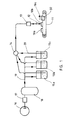
- Figure 1 shows equipment for the dosing of sample plates 10, in which the sample plates 10a, 10b and 10c have been placed on a belt conveyor 11. Above the conveyor 11 and the sample plates 10 there is dosing equipment for the liquid to be dosed, which comprises a dosing nozzle 12, a solenoid valve 13, a distributing valve 14 and liquid containers 15a, 15b and 15c.
- Compressed air is introduced into the liquid containers by means of equipment comprising a compressor 16, a pressure reduction valve 17 and a compressed air tank 18.
- the compressed air tank 18 is connected via tubes 19 to the liquid containers 15 so that the liquid containers are also at the same pressure as the compressed air tank.
- the distributing valve 14 to choose the container 15 from which liquid is taken to the dosing nozzle 12.
- the container 15a of the dosing equipment of Figure 1 contains the liquid used for the coating of the wells of the microplate used as the sample plate.
- the liquid container 15b contains liquid for washing the coating solution and the liquid container 15c rinsing liquid.
- the sample plates 10 can be moved in relation to the dosing nozzle 12 by means of a conveyor 11, in which case the dosing of the liquid can be carried out into all the sample wells of the microplate 10 one by one. It is also possible to arrange the sample plate to move sideways, but this example only includes the movement in one direction caused by the belt conveyor 11. In such case the dosing can be carried out in one row of sample wells at a time.
- the dosing nozzle 12 must then have as many nozzle tips as there are sample wells next to each other in one row of the sample plate.
- the structure of the dosing nozzle is described in more detail in Figure 3.
- FIG 1 there is an shaker device 32 in conjunction with the belt conveyor 11, which causes the sample plate 10c on the belt to be shaken after the dosing of the liquid.
- the purpose of the shaker device is to remove air bubbles from the dosed liquid and to ensure that the liquid dosed into the sample well of the sample plate 10 is at the bottom of the well and in contact with the walls of the well. Removal of air bubbles is important, particularly in the dosing of sample well coating liquid, but equally in the dosing of other liquids.
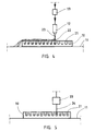
- Figure 2 shows the situation of dosing of liquid into the sample well of a sample plate. It can be seen from Figure 2 that from the dosing nozzle 12 above the sample plate 10, liquid 22 is dosed into the sample well 21 of the sample plate 10 which liquid can be, for example, liquid meant for the coating of the sample well 21 or sample solution.
- the sample well 21 rinsing liquid can, however, also be dosed in the same way.
- Figure 2 illustrates with an arrow the fact that the sample plate 10 on the conveyor 11 is moving in relation to the dosing nozzle 12.
- the movement of the sample plate 10 has been arranged to take place periodically, in such a way that the sample well 21 is always stopped at the dosing nozzle 12 for dosing.
- the sample plate 10 is moved in such a way that the next sample well or row of sample wells moves to the dosing nozzle 12.
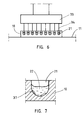
- Figure 3 shows the dosing equipment in Figure 2 seen from another direction. It can be seen from the figure that the dosing nozzle 12 of the sample plate 10 which is on the conveyor 11 comprises several nozzle tips 23, the number of which is the same as the number of the sample wells 21 in one row of the sample plate 10. In this way it is possible to dose into the entire row of sample wells at once when the sample plate has been stopped for dosing.
- Figure 4 shows another embodiment of the sampling equipment in Figure 2, in which the movement of the sample plate 10 is continuous.
- the amount of liquid 22 coming from the dosing nozzle 12 has been adjusted to be such that a sample well 21 moves away from the nozzle 12 only after the amount of liquid dosed into the sample well 21 is sufficient.
- the sample plate 10 proceeds at a uniform speed, each row of sample wells is dosed in turn.
- the number of dosing tips 23 in the dosing nozzle 12 is also in this example equal to the number of sample wells adjacent to each other in one row of a sample plate.
- FIG. 5 shows another embodiment of the vibrator device used in conjunction with the dosing of the sample plate 10.
- the vibrator device comprises a vibrator element 33, which is, for example, an ultrasonic vibrator, to which one or more needles or spikes 34 have been attached.
- the needles 34 are dipped in the liquid dosed into the sample well 21 of the sample plate 10, after which the liquid in the well is made to vibrate using the vibrator device. In this way, air bubbles are removed from the dosed liquid and at the same time it is ensured that the dosed liquid is well in contact with the walls of the sample well 21.
- the shaker described in Figure 1 or the ultrasonic vibrator described here, or both can be used for this purpose.
- the needles 34 fixed to the vibrator element 33 can be placed in a row which has as many needles as there are sample wells 21 in a row in the sample plate 10.
- the arrangement then corresponds to the dosing nozzle 12 described in Figure 3, which has as many nozzle tips as there are sample wells in a row in the sample plate.
- the difference is that the nozzle tips of the dosing nozzle are not dipped into the sample wells of the sample plate.
- the points of the row of needles 34 of the vibrator element 33 are, however, dipped into the liquids dosed into the sample wells 21 of the sample plate 10.
- the sample plate can be centrifuged.
- the purpose of centrifuging is to ensure that the liquid dosed will certainly go to the bottom of the sample well. At the same time, air bubbles are removed from the liquid.
- a centrifuge and various vibrators can be alternatives to each other, but also complementary to each other when used together.
- Figure 7 shows a vertical section of the sample well 21 of the sample plate 10, into which liquid 22 has been dosed. It can be seen from the figure that there remain air bubbles 37 between the liquid 22 and the wall of the sample well 21. Particularly when the sample plate 21 is small and its bottom part is angular in shape, the entire bottom part of the sample well may remain empty. It is clear that if the sample well 21 is filled incompletely like this, the walls of the sample well will not be properly coated. Likewise, if the sample well has to be washed or rinsed, rinsing and washing cannot be properly carried out when the well has air bubbles in it and is incompletely filled. According to the invention, incomplete filling of a sample well can be avoided and air bubbles removed by means of vibrators as described in Figures 1, 5 or 6, or by means of a centrifuge as described in Figure 8.
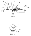
- FIG 8 shows an equipment arrangement which incorporates a centrifuge 30.
- This equipment comprises a sample plate 10c on a conveyor 11, and another sample plate 10d, which has already been placed in the centrifuge 30 in such a way that the sample wells open towards the axis 35 of the drum 31 of the centrifuge 30.
- the drum 31 rotates, the liquid in the sample wells of the sample plate 10 moves to the bottom of the sample well. In this way the liquid in the sample well is efficiently moved to the bottom of the sample plate and any air bubbles in the liquid are removed.
- Figure 9 shows separately the rotatable drum 31 of the centrifuge 30 and the sample plate placed in it as described in Figure 6.
- sample plates 10 will not empty when they are placed in the drum, even if the sample plates 10 are upside down at times.
- Centrifuging can also be used for emptying a sample well.
- Figure 10 shows equipment, or part of it, which has a centrifuge 24 used for emptying a sample well.
- the conveyor 11 conveys the sample plate 10 to the emptying centrifuge 24.
- the centrifuge 24 comprises a drum 25, into the holders of which a sample plate 10 is placed in such a way that the sample wells open away from the axis 36 of the drum 31 of the centrifuge 30.
- the drum 25 is rotated by means of a rotating motor 27.
- Figure 11 is seen the drum 25 of the centrifuge in Figure 10 as seen from the direction of the axis and a sample plate 10 fixed to the circumference of the drum.
- sample wells of the sample plate As the sample will remain in the small sample wells of the sample plate due to the liquid's surface tension, even when the sample plate is turned upside down, various sample plates can be placed at different sides on the circumference of the drum 25 of the centrifuge 24.
- the sample wells of the sample plates 10 will not empty when they are placed on the circumference of the drum, even if the sample plates 10 are upside down at times. The sample wells are not emptied until centrifuging.
- Figure 12 shows the situation of emptying by centrifuging, in which a sample plate 10 fixed to the circumference of the drum 25 of the centrifuge 24 is rotated by means of a rotating motor 27.
- the liquid in the sample wells 21 of sample plate 10 is centrifuged and removed by the action of centrifugal force from the sample wells.
- a protective casing 28 has been formed in the centrifuge 24 for the liquid that is removed and an opening 29 in it, through which the liquid removed with the centrifuge can be collected. In this way, even small sample wells can be efficiently emptied, in which case washing and rinsing function in the intended way.
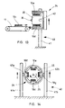
- FIG 13 there is a sample plate 10c conveyor 11 and another embodiment of the centrifuge 24, which has been fixed to a stand.
- the centrifuge 24 has been placed in the slide 41 of the stand 40 in such a way that it is possible to move the centrifuge 24 vertically.
- the centrifuge 24 is in the stand 40 in its upper position.
- the sample plates 10c to be fed into the centrifuge 24 come into the holders situated on the circumference of the drum 25 of the centrifuge 24 in such a way that the sample wells of the sample plates 10d and 10e open towards the inside of the drum 25, that is, towards the axis 35 of the drum 25.
- the sample wells of the sample plates 10d and 10e are so small that due to the liquid's surface tension the liquid in the sample wells is not removed although the sample wells are turned upside down.
- FIG 14 is seen the centrifuge 24 in Figure 13, seen from another direction.
- the centrifuge 24 is in the stand 40 in its upper position supported on the slides 41, and the axis 35 of the drum 25 is horizontal.
- the sample plates 10d-10g are on the circumference of the drum 25 in their holders with the sample wells directed towards the axis 35 of the drum 25. Thus directed, the sample plates 10d-10g are at the filling stage.
- the centrifuge 24 can now be started, in which case the liquid in the sample wells of the sample plates 10d-10g is centrifuged by the action of centrifugal force into the bottom of the sample wells and the air bubbles are removed from the sample wells.
- the centrifuge 24 is in the stand 40 in its lower position. Now the sample plates 10c to be fed into the centrifuge 24 come into the holders situated on the circumference of the centrifuge 24 drum 25 in such a way that the sample wells of the sample plates 10d and 10e open outwards, that is away from the axis 35 of the drum 25.
- FIG 16 shows the centrifuge 24 from another direction.
- the centrifuge 24 is in the stand 40 in its lower position supported on the slides 41, and the axis 35 of the drum 25 is horizontal.
- the sample plates 10d-10g are not, however, centrifuged in this position, but the centrifuge 24 is tumed 90° by means of axles 42a and 42b so that the axis 35 of the drum 25 is vertical.
- the centrifuge 24 is in the sample well emptying position, in which the centrifuge 24 has been turned around the axle 42 in such a way that the axis 35 of the drum 25 is vertical.
- the sample wells of the sample plates 10d-10g which are directed away from the axis 35 of the drum 25, are emptied by the action of centrifugal force and the liquid in the sample wells is centrifuged to the walls of the protective casing 28 of the centrifuge 24 and from there further to the bottom of the centrifuge.
- This embodiment is advantageous because the liquid that is being removed from the sample wells will not fall from the walls of the protective casing 28 back onto the sample plates when centrifuged. The liquid is removed from the bottom of the protective casing 28 in the way described in Figure 12, for example.
Landscapes
- Chemical & Material Sciences (AREA)
- Health & Medical Sciences (AREA)
- Chemical Kinetics & Catalysis (AREA)
- Clinical Laboratory Science (AREA)
- Analytical Chemistry (AREA)
- General Health & Medical Sciences (AREA)
- Life Sciences & Earth Sciences (AREA)
- Biochemistry (AREA)
- Physics & Mathematics (AREA)
- General Physics & Mathematics (AREA)
- Immunology (AREA)
- Pathology (AREA)
- Automatic Analysis And Handling Materials Therefor (AREA)
- Cleaning By Liquid Or Steam (AREA)
- Sampling And Sample Adjustment (AREA)
- Centrifugal Separators (AREA)
Applications Claiming Priority (4)
| Application Number | Priority Date | Filing Date | Title |
|---|---|---|---|
| FI974521A FI974521A0 (fi) | 1997-12-15 | 1997-12-15 | Foerfarande och anordning foer hantering av objektglas |
| FI974521 | 1997-12-15 | ||
| FI982645A FI982645A (fi) | 1997-12-15 | 1998-12-07 | Menetelmä ja laite näytelevyjen käsittelemiseksi |
| FI982645 | 1998-12-07 |
Publications (3)
| Publication Number | Publication Date |
|---|---|
| EP0937502A2 true EP0937502A2 (de) | 1999-08-25 |
| EP0937502A3 EP0937502A3 (de) | 2000-05-31 |
| EP0937502B1 EP0937502B1 (de) | 2002-05-02 |
Family
ID=26160485
Family Applications (1)
| Application Number | Title | Priority Date | Filing Date |
|---|---|---|---|
| EP98660141A Expired - Lifetime EP0937502B1 (de) | 1997-12-15 | 1998-12-15 | Verfahren und Vorrichtung zur Behandlung von Musterplatten |
Country Status (4)
| Country | Link |
|---|---|
| US (1) | US6112603A (de) |
| EP (1) | EP0937502B1 (de) |
| DE (1) | DE69805156T2 (de) |
| FI (1) | FI982645A (de) |
Cited By (6)
| Publication number | Priority date | Publication date | Assignee | Title |
|---|---|---|---|---|
| WO2001067114A1 (en) * | 2000-03-08 | 2001-09-13 | Tibotec Bvba | Method and apparatus for dispensing a liquid into a series of wells |
| WO2002071051A3 (en) * | 2001-02-14 | 2003-01-09 | Picoliter Inc | Acoustic sample introduction for analysis and/or processing |
| EP2835178A1 (de) * | 2013-08-06 | 2015-02-11 | AusBio R&D Europe GmbH | Zentrifuge und Verfahren zum Zentrifugieren einer Reaktionsgefäßeinheit |
| DE102016101163A1 (de) | 2016-01-22 | 2017-07-27 | Bluecatbio Gmbh | Zentrifuge |
| DE102017113583A1 (de) | 2017-06-20 | 2018-12-20 | Bluecatbio Gmbh | Zentrifuge |
| DE102021124023A1 (de) | 2021-09-16 | 2023-03-16 | Bluecatbio Gmbh | Zentrifuge und Verfahren zum Reinigen einer Zentrifuge |
Families Citing this family (6)
| Publication number | Priority date | Publication date | Assignee | Title |
|---|---|---|---|---|
| JP2009264927A (ja) * | 2008-04-25 | 2009-11-12 | Micronics Kk | マイクロプレート処理装置 |
| US9302234B2 (en) | 2012-10-09 | 2016-04-05 | Kunio Misono | Stirring devices |
| GB201400836D0 (en) * | 2014-01-17 | 2014-03-05 | Ttp Labtech Ltd | Microplate content agitation apparatus and method |
| TWI766942B (zh) | 2017-02-13 | 2022-06-11 | 美商海科生醫有限責任公司 | 透過利用瞬態和穩態間隔振動移液管來混合流體或介質的設備和方法 |
| JP7095613B2 (ja) * | 2019-01-31 | 2022-07-05 | 株式会社Jvcケンウッド | 洗浄装置及び洗浄方法 |
| US20230072202A1 (en) * | 2021-09-07 | 2023-03-09 | Grenova, Inc. | Laboratory well plate washing device and associated method |
Citations (4)
| Publication number | Priority date | Publication date | Assignee | Title |
|---|---|---|---|---|
| US4004150A (en) * | 1975-05-01 | 1977-01-18 | Samuel Natelson | Analytical multiple component readout system |
| US4847205A (en) * | 1987-04-08 | 1989-07-11 | Martin Marietta Energy Systems, Inc. | Device and method for automated separation of a sample of whole blood into aliquots |
| EP0388144A2 (de) * | 1989-03-15 | 1990-09-19 | Takara Shuzo Co. Ltd. | Reaktor für Reagenzien |
| US5792654A (en) * | 1997-05-12 | 1998-08-11 | Neogen Corporation | Microorganism culture tray |
Family Cites Families (4)
| Publication number | Priority date | Publication date | Assignee | Title |
|---|---|---|---|---|
| US3591862A (en) * | 1970-01-12 | 1971-07-06 | Ultrasonic Systems | Ultrasonic motor transmission system |
| US4147294A (en) * | 1978-02-22 | 1979-04-03 | Beckman Instruments, Inc. | Rotor carrier for microtitration plate |
| US5073578A (en) * | 1990-02-23 | 1991-12-17 | Unilever Patent Holdings B.V. | Core-shell copolymer emulsions for flexible coatings |
| US5707861A (en) * | 1995-09-14 | 1998-01-13 | Scientific Industries, Inc. | Disintegrator of living cells |
-
1998
- 1998-12-07 FI FI982645A patent/FI982645A/fi not_active Application Discontinuation
- 1998-12-14 US US09/210,570 patent/US6112603A/en not_active Expired - Lifetime
- 1998-12-15 DE DE69805156T patent/DE69805156T2/de not_active Expired - Lifetime
- 1998-12-15 EP EP98660141A patent/EP0937502B1/de not_active Expired - Lifetime
Patent Citations (4)
| Publication number | Priority date | Publication date | Assignee | Title |
|---|---|---|---|---|
| US4004150A (en) * | 1975-05-01 | 1977-01-18 | Samuel Natelson | Analytical multiple component readout system |
| US4847205A (en) * | 1987-04-08 | 1989-07-11 | Martin Marietta Energy Systems, Inc. | Device and method for automated separation of a sample of whole blood into aliquots |
| EP0388144A2 (de) * | 1989-03-15 | 1990-09-19 | Takara Shuzo Co. Ltd. | Reaktor für Reagenzien |
| US5792654A (en) * | 1997-05-12 | 1998-08-11 | Neogen Corporation | Microorganism culture tray |
Cited By (36)
| Publication number | Priority date | Publication date | Assignee | Title |
|---|---|---|---|---|
| WO2001067114A1 (en) * | 2000-03-08 | 2001-09-13 | Tibotec Bvba | Method and apparatus for dispensing a liquid into a series of wells |
| EP1134586A1 (de) * | 2000-03-08 | 2001-09-19 | Tibotec N.V. | Verfahen zur Abgabe von Flüssigkeiten in einer Vielzahl von Probengefässen |
| WO2002071051A3 (en) * | 2001-02-14 | 2003-01-09 | Picoliter Inc | Acoustic sample introduction for analysis and/or processing |
| DE202014011542U1 (de) | 2013-08-06 | 2022-01-31 | Yantai Ausbio Laboratories Co., Ltd. | Zentrifuge zum Zentrifugieren einer Reaktions-Gefäßeinheit |
| US10338063B2 (en) | 2013-08-06 | 2019-07-02 | Yantai Ausbio Laboratories Co., Ltd. | Centrifuge and method for centrifuging a reaction vessel unit |
| WO2015018878A3 (en) * | 2013-08-06 | 2015-05-07 | Yantai Ausbio Laboratories Co., Ltd. | Centrifuge and method for centrifuging a reaction vessel unit |
| US11885799B2 (en) | 2013-08-06 | 2024-01-30 | Yantai Ausbio Laboratories Co., Ltd. | Centrifuge including a magnetic element and method for centrifuging a reaction vessel unit |
| CN105517711A (zh) * | 2013-08-06 | 2016-04-20 | 烟台澳斯邦生物工程有限公司 | 用于使反应容器单元受离心力作用的离心机与方法 |
| JP2016534865A (ja) * | 2013-08-06 | 2016-11-10 | ヤンタイ・アウスビオ・ラボラトリーズ・カンパニー・リミテッド | 遠心分離機、および反応容器ユニットに遠心力を作用させるための方法 |
| EP3030353B1 (de) | 2013-08-06 | 2017-05-10 | Yantai AusBio Laboratories Co., Ltd. | Zentrifuge und verfahren zum zentrifugieren einer reaktionsgefässeinheit |
| JP2019013917A (ja) * | 2013-08-06 | 2019-01-31 | ヤンタイ・アウスビオ・ラボラトリーズ・カンパニー・リミテッド | 遠心分離機、および反応容器ユニットに遠心力を作用させるための方法 |
| DE202014011068U1 (de) | 2013-08-06 | 2017-08-16 | Yantai Ausbio Laboratories Co., Ltd. | Zentrifuge zum Zentrifugieren einer Reaktions-Gefässeinheit |
| DE202014011072U1 (de) | 2013-08-06 | 2017-08-17 | Yantai Ausbio Laboratories Co., Ltd. | Zentrifuge zum Zentrifugieren einer Reaktions-Gefäßeinheit |
| DE202014011073U1 (de) | 2013-08-06 | 2017-08-17 | Yantai Ausbio Laboratories Co., Ltd. | Zentrifuge zum Zentrifugieren einer Reaktions-Gefäßeinheit |
| DE202014011074U1 (de) | 2013-08-06 | 2017-08-17 | Yantai Ausbio Laboratories Co., Ltd. | Zentrifuge zum Zentrifugieren einer Reaktions-Gefäßeinheit |
| DE202014011071U1 (de) | 2013-08-06 | 2017-08-18 | Yantai Ausbio Laboratories Co., Ltd. | Zentrifuge zum Zentrifugieren einer Reaktions-Gefäßeinheit |
| DE202014011611U1 (de) | 2013-08-06 | 2023-06-16 | Yantai Ausbio Laboratories Co., Ltd. | Zentrifuge zum Zentrifugieren einer Reaktions-Gefäßeinheit |
| RU2672746C2 (ru) * | 2013-08-06 | 2018-11-19 | Яньтай Аусбио Лабораториз Ко., Лтд. | Центрифуга для центрифугирования блока реакционных ячеек и способ |
| US11885798B2 (en) | 2013-08-06 | 2024-01-30 | Yantai Ausbio Laboratories Co., Ltd. | Centrifuge and method for loading and centrifuging a reaction vessel unit |
| DE202014010544U1 (de) | 2013-08-06 | 2015-11-26 | Yantai Ausbio Laboratories Co., Ltd. | Zentrifuge zum Zentrifugieren einer Reaktions-Gefäßeinheit |
| WO2015018878A2 (en) * | 2013-08-06 | 2015-02-12 | Yantai Ausbio Laboratories Co., Ltd. | Centrifuge and method for centrifuging a reaction vessel unit |
| DE202014011070U1 (de) | 2013-08-06 | 2017-08-21 | Yantai Ausbio Laboratories Co., Ltd. | Zentrifuge zum Zentrifugieren einer Reaktions-Gefäßeinheit |
| CN105517711B (zh) * | 2013-08-06 | 2019-08-02 | 烟台澳斯邦生物工程有限公司 | 用于使反应容器单元受离心力作用的离心机与方法 |
| US10928387B2 (en) | 2013-08-06 | 2021-02-23 | Yantai Ausbio Laboratories Co., Ltd. | Centrifuge including a magnetic element and method for centrifuging a reaction vessel unit and using a magnetic element |
| DE202014011614U1 (de) | 2013-08-06 | 2023-07-04 | Yantai Ausbio Laboratories Co., Ltd. | Zentrifuge zum Zentrifugieren einer Reaktions-Gefäßeinheit |
| DE202014011521U1 (de) | 2013-08-06 | 2021-11-18 | Yantai Ausbio Laboratories Co., Ltd. | Zentrifuge und System zum Waschen von magnetischen Partikeln in einer Reaktions-Gefäßeinheit |
| DE202014011543U1 (de) | 2013-08-06 | 2022-01-31 | Yantai Ausbio Laboratories Co., Ltd. | Zentrifuge zum Zentrifugieren einer Reaktions-Gefäßeinheit |
| EP2835178A1 (de) * | 2013-08-06 | 2015-02-11 | AusBio R&D Europe GmbH | Zentrifuge und Verfahren zum Zentrifugieren einer Reaktionsgefäßeinheit |
| DE202014011612U1 (de) | 2013-08-06 | 2023-06-16 | Yantai Ausbio Laboratories Co., Ltd. | Zentrifuge zum Waschen einer Reaktions-Gefäßeinheit |
| DE102016101163A1 (de) | 2016-01-22 | 2017-07-27 | Bluecatbio Gmbh | Zentrifuge |
| US11117142B2 (en) | 2016-01-22 | 2021-09-14 | Bluecatbio Gmbh | Centrifuge with linear drive |
| US11738354B2 (en) | 2017-06-20 | 2023-08-29 | Bluecatbio Gmbh | Centrifuge with drainage |
| DE102017113583A1 (de) | 2017-06-20 | 2018-12-20 | Bluecatbio Gmbh | Zentrifuge |
| WO2018234420A1 (de) | 2017-06-20 | 2018-12-27 | Bluecatbio Gmbh | Zentrifuge |
| EP4151315A1 (de) | 2021-09-16 | 2023-03-22 | BlueCatBio GmbH | Zentrifuge und verfahren zum reinigen einer zentrifuge |
| DE102021124023A1 (de) | 2021-09-16 | 2023-03-16 | Bluecatbio Gmbh | Zentrifuge und Verfahren zum Reinigen einer Zentrifuge |
Also Published As
| Publication number | Publication date |
|---|---|
| DE69805156D1 (de) | 2002-06-06 |
| EP0937502B1 (de) | 2002-05-02 |
| US6112603A (en) | 2000-09-05 |
| DE69805156T2 (de) | 2002-12-19 |
| FI982645A0 (fi) | 1998-12-07 |
| FI982645A (fi) | 1999-06-16 |
| EP0937502A3 (de) | 2000-05-31 |
Similar Documents
| Publication | Publication Date | Title |
|---|---|---|
| US6112603A (en) | Method and a device for handling sample plates | |
| US5215376A (en) | Method for causing vortices in a test tube | |
| US5736100A (en) | Chemical analyzer non-invasive stirrer | |
| US5005981A (en) | Apparatus for method for causing vortices in a test tube | |
| EP1032469B1 (de) | Vorrichtung und verfahren zur trennung von flüssigen und festen phasen in organischen festphasensynthesen | |
| JP2825768B2 (ja) | 分析装置 | |
| JP4313420B2 (ja) | 反応容器装置 | |
| US6197255B1 (en) | Chemical analyzing apparatus | |
| FI113703B (fi) | Diagnostinen mittauslaite | |
| EP0355801A2 (de) | Automatischer Wirbelmischer | |
| JPH0458340B2 (de) | ||
| JP7113413B2 (ja) | 薬剤払出し装置、散薬秤量装置及び薬剤分包システム | |
| US6196278B1 (en) | Powder filling utilizing vibrofluidization | |
| CN101375167A (zh) | 化验装置处理设备及方法 | |
| CA3205528A1 (en) | System for transporting loose sterile closure elements | |
| JP4901035B2 (ja) | パーツの送給装置 | |
| JPH0116721B2 (de) | ||
| US11142353B2 (en) | Automated batch filling apparatus | |
| EP1558901A1 (de) | Automatische kombinationswaagevorrichtung | |
| SU997778A1 (ru) | Устройство дл перемешивани | |
| JPS5841909B2 (ja) | 錠剤選別装置 | |
| US4965984A (en) | Method and apparatus for aligning elongated articles | |
| KR101301622B1 (ko) | 약품공급장치의 정량 분류 구조 | |
| JPH0458319B2 (de) | ||
| WO1990007987A1 (en) | Vibratory article coater and method |
Legal Events
| Date | Code | Title | Description |
|---|---|---|---|
| PUAI | Public reference made under article 153(3) epc to a published international application that has entered the european phase |
Free format text: ORIGINAL CODE: 0009012 |
|
| AK | Designated contracting states |
Kind code of ref document: A2 Designated state(s): DE ES FR GB IT NL SE |
|
| AX | Request for extension of the european patent |
Free format text: AL;LT;LV;MK;RO;SI |
|
| PUAL | Search report despatched |
Free format text: ORIGINAL CODE: 0009013 |
|
| AK | Designated contracting states |
Kind code of ref document: A3 Designated state(s): AT BE CH CY DE DK ES FI FR GB GR IE IT LI LU MC NL PT SE |
|
| AX | Request for extension of the european patent |
Free format text: AL;LT;LV;MK;RO;SI |
|
| RIC1 | Information provided on ipc code assigned before grant |
Free format text: 7G 01N 35/02 A, 7B 01L 3/02 B |
|
| 17P | Request for examination filed |
Effective date: 20001130 |
|
| AKX | Designation fees paid |
Free format text: DE ES FR GB IT NL SE |
|
| 17Q | First examination report despatched |
Effective date: 20010402 |
|
| GRAG | Despatch of communication of intention to grant |
Free format text: ORIGINAL CODE: EPIDOS AGRA |
|
| GRAG | Despatch of communication of intention to grant |
Free format text: ORIGINAL CODE: EPIDOS AGRA |
|
| GRAH | Despatch of communication of intention to grant a patent |
Free format text: ORIGINAL CODE: EPIDOS IGRA |
|
| REG | Reference to a national code |
Ref country code: GB Ref legal event code: IF02 |
|
| GRAH | Despatch of communication of intention to grant a patent |
Free format text: ORIGINAL CODE: EPIDOS IGRA |
|
| GRAA | (expected) grant |
Free format text: ORIGINAL CODE: 0009210 |
|
| AK | Designated contracting states |
Kind code of ref document: B1 Designated state(s): DE ES FR GB IT NL SE |
|
| PG25 | Lapsed in a contracting state [announced via postgrant information from national office to epo] |
Ref country code: NL Free format text: LAPSE BECAUSE OF FAILURE TO SUBMIT A TRANSLATION OF THE DESCRIPTION OR TO PAY THE FEE WITHIN THE PRESCRIBED TIME-LIMIT Effective date: 20020502 Ref country code: IT Free format text: LAPSE BECAUSE OF FAILURE TO SUBMIT A TRANSLATION OF THE DESCRIPTION OR TO PAY THE FEE WITHIN THE PRE;WARNING: LAPSES OF ITALIAN PATENTS WITH EFFECTIVE DATE BEFORE 2007 MAY HAVE OCCURRED AT ANY TIME BEFORE 2007. THE CORRECT EFFECTIVE DATE MAY BE DIFFERENT FROM THE ONE RECORDED.SCRIBED TIME-LIMIT Effective date: 20020502 |
|
| REG | Reference to a national code |
Ref country code: GB Ref legal event code: FG4D |
|
| REF | Corresponds to: |
Ref document number: 69805156 Country of ref document: DE Date of ref document: 20020606 |
|
| PG25 | Lapsed in a contracting state [announced via postgrant information from national office to epo] |
Ref country code: SE Free format text: LAPSE BECAUSE OF FAILURE TO SUBMIT A TRANSLATION OF THE DESCRIPTION OR TO PAY THE FEE WITHIN THE PRESCRIBED TIME-LIMIT Effective date: 20020802 |
|
| NLV1 | Nl: lapsed or annulled due to failure to fulfill the requirements of art. 29p and 29m of the patents act | ||
| ET | Fr: translation filed | ||
| PG25 | Lapsed in a contracting state [announced via postgrant information from national office to epo] |
Ref country code: ES Free format text: LAPSE BECAUSE OF FAILURE TO SUBMIT A TRANSLATION OF THE DESCRIPTION OR TO PAY THE FEE WITHIN THE PRESCRIBED TIME-LIMIT Effective date: 20021128 |
|
| PLBE | No opposition filed within time limit |
Free format text: ORIGINAL CODE: 0009261 |
|
| STAA | Information on the status of an ep patent application or granted ep patent |
Free format text: STATUS: NO OPPOSITION FILED WITHIN TIME LIMIT |
|
| 26N | No opposition filed |
Effective date: 20030204 |
|
| REG | Reference to a national code |
Ref country code: FR Ref legal event code: PLFP Year of fee payment: 18 |
|
| REG | Reference to a national code |
Ref country code: FR Ref legal event code: PLFP Year of fee payment: 19 |
|
| PGFP | Annual fee paid to national office [announced via postgrant information from national office to epo] |
Ref country code: GB Payment date: 20161228 Year of fee payment: 19 |
|
| PGFP | Annual fee paid to national office [announced via postgrant information from national office to epo] |
Ref country code: FR Payment date: 20161227 Year of fee payment: 19 |
|
| PGFP | Annual fee paid to national office [announced via postgrant information from national office to epo] |
Ref country code: DE Payment date: 20161229 Year of fee payment: 19 |
|
| REG | Reference to a national code |
Ref country code: DE Ref legal event code: R119 Ref document number: 69805156 Country of ref document: DE |
|
| GBPC | Gb: european patent ceased through non-payment of renewal fee |
Effective date: 20171215 |
|
| REG | Reference to a national code |
Ref country code: FR Ref legal event code: ST Effective date: 20180831 |
|
| PG25 | Lapsed in a contracting state [announced via postgrant information from national office to epo] |
Ref country code: FR Free format text: LAPSE BECAUSE OF NON-PAYMENT OF DUE FEES Effective date: 20180102 Ref country code: DE Free format text: LAPSE BECAUSE OF NON-PAYMENT OF DUE FEES Effective date: 20180703 |
|
| PG25 | Lapsed in a contracting state [announced via postgrant information from national office to epo] |
Ref country code: GB Free format text: LAPSE BECAUSE OF NON-PAYMENT OF DUE FEES Effective date: 20171215 |