EP0936058A1 - Form zur Herstellung von gabelförmigen Gegenständen - Google Patents
Form zur Herstellung von gabelförmigen Gegenständen Download PDFInfo
- Publication number
- EP0936058A1 EP0936058A1 EP98830062A EP98830062A EP0936058A1 EP 0936058 A1 EP0936058 A1 EP 0936058A1 EP 98830062 A EP98830062 A EP 98830062A EP 98830062 A EP98830062 A EP 98830062A EP 0936058 A1 EP0936058 A1 EP 0936058A1
- Authority
- EP
- European Patent Office
- Prior art keywords
- casting dies
- lateral
- dies
- die
- fork
- Prior art date
- Legal status (The legal status is an assumption and is not a legal conclusion. Google has not performed a legal analysis and makes no representation as to the accuracy of the status listed.)
- Granted
Links
- 238000004519 manufacturing process Methods 0.000 title claims description 14
- 238000005266 casting Methods 0.000 claims abstract description 115
- 230000008878 coupling Effects 0.000 claims abstract description 15
- 238000010168 coupling process Methods 0.000 claims abstract description 15
- 238000005859 coupling reaction Methods 0.000 claims abstract description 15
- 239000000463 material Substances 0.000 claims description 6
- 238000000034 method Methods 0.000 claims description 5
- 229910052751 metal Inorganic materials 0.000 claims description 4
- 239000002184 metal Substances 0.000 claims description 4
- 239000012768 molten material Substances 0.000 claims description 2
- 238000007711 solidification Methods 0.000 claims description 2
- 230000008023 solidification Effects 0.000 claims description 2
- 238000001816 cooling Methods 0.000 claims 1
- 238000002347 injection Methods 0.000 description 4
- 239000007924 injection Substances 0.000 description 4
- 238000003825 pressing Methods 0.000 description 4
- 230000015572 biosynthetic process Effects 0.000 description 2
- 238000010586 diagram Methods 0.000 description 2
- 230000008569 process Effects 0.000 description 2
- 239000000047 product Substances 0.000 description 2
- 238000005096 rolling process Methods 0.000 description 2
- 239000000243 solution Substances 0.000 description 2
- 238000009966 trimming Methods 0.000 description 2
- 229910000838 Al alloy Inorganic materials 0.000 description 1
- 230000001133 acceleration Effects 0.000 description 1
- 230000009471 action Effects 0.000 description 1
- 230000002411 adverse Effects 0.000 description 1
- 239000007795 chemical reaction product Substances 0.000 description 1
- 238000006073 displacement reaction Methods 0.000 description 1
- 238000009826 distribution Methods 0.000 description 1
- 230000008030 elimination Effects 0.000 description 1
- 238000003379 elimination reaction Methods 0.000 description 1
- 239000012530 fluid Substances 0.000 description 1
- 238000005242 forging Methods 0.000 description 1
- 239000002991 molded plastic Substances 0.000 description 1
- 210000000056 organ Anatomy 0.000 description 1
- 230000009467 reduction Effects 0.000 description 1
Images


Classifications
-
- B—PERFORMING OPERATIONS; TRANSPORTING
- B22—CASTING; POWDER METALLURGY
- B22D—CASTING OF METALS; CASTING OF OTHER SUBSTANCES BY THE SAME PROCESSES OR DEVICES
- B22D17/00—Pressure die casting or injection die casting, i.e. casting in which the metal is forced into a mould under high pressure
- B22D17/20—Accessories: Details
- B22D17/22—Dies; Die plates; Die supports; Cooling equipment for dies; Accessories for loosening and ejecting castings from dies
-
- B—PERFORMING OPERATIONS; TRANSPORTING
- B29—WORKING OF PLASTICS; WORKING OF SUBSTANCES IN A PLASTIC STATE IN GENERAL
- B29C—SHAPING OR JOINING OF PLASTICS; SHAPING OF MATERIAL IN A PLASTIC STATE, NOT OTHERWISE PROVIDED FOR; AFTER-TREATMENT OF THE SHAPED PRODUCTS, e.g. REPAIRING
- B29C45/00—Injection moulding, i.e. forcing the required volume of moulding material through a nozzle into a closed mould; Apparatus therefor
- B29C45/17—Component parts, details or accessories; Auxiliary operations
- B29C45/26—Moulds
-
- B—PERFORMING OPERATIONS; TRANSPORTING
- B29—WORKING OF PLASTICS; WORKING OF SUBSTANCES IN A PLASTIC STATE IN GENERAL
- B29C—SHAPING OR JOINING OF PLASTICS; SHAPING OF MATERIAL IN A PLASTIC STATE, NOT OTHERWISE PROVIDED FOR; AFTER-TREATMENT OF THE SHAPED PRODUCTS, e.g. REPAIRING
- B29C45/00—Injection moulding, i.e. forcing the required volume of moulding material through a nozzle into a closed mould; Apparatus therefor
- B29C45/17—Component parts, details or accessories; Auxiliary operations
- B29C45/26—Moulds
- B29C45/33—Moulds having transversely, e.g. radially, movable mould parts
Definitions
- the present invention relates to a die or mould for manufacturing fork-shaped articles, of the type comprising: at least one pair of inner casting dies movable in mutual approach relation and able to be coupled in correspondence with respective junction surfaces mutually matched and opposed; at least one pair of lateral casting dies movable in lateral approach to the inner casting dies and able to be coupled thereto from respectively opposite parts, in correspondence with mutually matched lateral junction surfaces, presented respectively by the lateral casting dies and by the inner casting dies, said inner and said lateral casting dies being movable between an open condition wherein they are mutually distanced and a closed condition wherein they are mutually coupled to define at least one casting cavity presenting at least two terminal portions, reproducing the shape of the arms of the fork-shaped article and internally defined each in one of said lateral casting dies, and an intermediate potion defined between said inner casting dies extending between said terminal portions and reproducing the shape of said connecting bar of the fork-shaped article.
- the invention is aimed at the manufacture of arresting forks of the type usually employed for selectively stopping the coiling drums of the devices for rolling up safety belts for motor vehicles and the like.
- the innovative concepts of the invention can advantageously be exploited for the manufacture of any type of fork-shaped article, i.e. one provided with a pair of distanced arms interconnected by a connecting bar, made of die-cast material or of injection-moulded plastic material, wherein the geometric and dimensional characteristics of the arms must meet rather strict geometric and shape tolerances.
- the devices for rolling up safety belts usually employed on motor vehicles and the like are fitted with a drum for coiling the belt on whose opposite ends are obtained circumferential teeth operatively engageable by the opposite arms of a locking fork. More specifically, the fork is engaged in a manner allowing it to oscillate to a fixed structure of the coiling device, for instance by means of a pair of hinge pins projecting from the opposite ends of a connecting bar extending between the aforementioned arms.
- Each of the arms of the fork presents a shaped groove wherein is operatively engaged a command organ which is sensitive to acceleration and/or to other critical parameters to command, if necessary, the coiling drum to lock.
- the locking action is performed by clutching teeth borne terminally by the arms of the fork element and engaging respectively with the circumferential teeth present on the drum.
- Forks of the type described above are generally manufactured in aluminium alloy or other die-cast material. Particular care is taken in designing and manufacturing the dies employed to manufacture the fork which, being part of a device able to intervene in emergency conditions to ensure persons' safety, must meet narrow geometric and shape tolerances to guarantee the proper operation and the reliability of the device itself.
- the dies employed for the manufacture of the forks comprise a pair of inner casting dies able to be mutually coupled by mutual approach in correspondence with respective matched junction surfaces, between which are obtained one or more forging cavities each reproducing in negative the conformation of the forks to be manufactured.
- each pressing cavity is essentially defined by an intermediate portion reproducing the shape of the connecting bar between the arms, terminally connected by parts opposite to two terminal portions reproducing the shape of the arms themselves.
- the coupling surfaces of the casting dies essentially join along a plane coinciding with the median plane of main development of each fork.
- of the terminal portions, as well as the intermediate portion of the pressing cavity are essentially subdivided into two semi-parts obtained in the coupling surfaces belonging respectively to one or the other inner casting dies.
- the terminal portions of the pressing cavity open on respective outer lateral surfaces of the inner casting dies, against which, from respectively opposite parts, can be coupled corresponding lateral surfaces of at least one pair of lateral casting dies movable perpendicularly with respect to the direction of mutual motion of the inner casting dies.
- the lateral casting dies act against the inner casting dies to close the pressing cavity in correspondence with the terminal portions thereof.
- a shaped projection set to define the shaped groove in the corresponding arm of the fork, as well as a possible recess set to define one of the aforesaid hinge pins of the arm itself.
- dies have also been manufactured wherein the entire shape of the arms of the fork is obtained in the lateral casting dies, whilst between the inner casting dies is defined only the intermediate portion of the casting cavity, essentially formed by a through channel.
- any mutual misalignments between the inner casting dies, whose junction surfaces essentially join along the main geometric plane of the fork to be manufactured, are prone to determine different geometric and dimensional imperfections, such as discontinuities and dimensional irregularities in relation to the thickness of the arms and variations in their mutual distance with respect to the nominal values, in addition to other drawbacks such as the formation of burrs on the development plane of the respectively opposite faces of the arms themselves.
- the main object of the present invention is to overcome the limits and drawbacks of the prior art, considerably improving the productive capacity and the geometric and dimensional precision of the die-cast or injection moulded articles.
- a die or mould for manufacturing fork-shaped articles characterised in that the opposed junction surfaces of the inner casting dies extend along a coupling profile that is external with respect to the perimeter development of the terminal portion of the casting cavity.
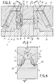
- the number 1 indicates in its entirety a die or mould for the manufacture of fork-shaped articles according to the present invention.
- the fork-shaped articles for the manufacture whereof the die 1 is employed comprise locking forks 2 for safety belt coiling devices.
- Each fork 2 essentially comprises a pair of parallel arms 3, each of which presents an end connected to a corresponding end of the other arm 3 by means of a connecting bar 4.
- Each arm 3 presents one or more clutching teeth 5 oriented on the opposite side to the end connected to the connecting bar 3.
- On an outer lateral surface of each arm 3 are set at least one guiding recess 6 and a hinge pin 7 projecting perpendicularly in correspondence with the attachment end of the connecting bar 3.
- the die 1 essentially comprises a pair of inner casting dies, and more specifically a lower casting die 8 and an upper casting die 9 which, in a way known in the prior art and therefore not described in detail herein, are slidingly guided according to a first direction of mutual motion, indicated by the arrow "A" in Figure 2.
- the inner casting dies 8, 9 are mutually movable between an opening condition wherein they are appropriately distanced one from the other, and a closed condition wherein as shown in Figures 2, 3, 4 they are mutually coupled by means of respective coupling surfaces 8a, 9a mutually matched and opposed.
- the die 1 further comprises a pair of lateral casting dies 10 movable in lateral approach to the inner casting dies 8, 9 and able to be coupled thereto from respectively opposite parts in correspondence with lateral junction surfaces 10a, 8b, 9b, mutually matched, presented respectively by the lateral casting dies 10 and by the inner casting dies 8, 9.
- the lateral casting dies are for instance fastened to respective moving carriages 11 slidingly guided on guide portions 12 integral with the lower inner casting die 8, and operatively engaged by thrust wedges 13 and by return columns 14 rigidly engaged with respect to the upper inner casting die 9.
- the operative engagement of the carriages 11 between the slides 12 and the wedges 13 with the respective return columns 14 is such that, as a result of the mutual motion transmitted to the inner casting dies 8, 9 from the open condition to the closed condition, the lateral casting dies 10 are in turn translated from an open condition wherein they are laterally distanced from the inner casting dies 8, 9, to a closed condition wherein they are laterally approached and coupled thereto from respectively opposite parts in correspondence with the respective lateral junction surfaces 10a, 8b, 9b.
- At least one casting cavity 15 presenting essentially at least two terminal portions 15a reproducing the profile of the arms 3 of the fork 2, and an intermediate portion 15b extending between the terminal portions 15a and reproducing the profile of the connecting bar 4.
- each of the terminal portions 15a of the casting cavity 15 is fully defined, as is clearly shown in Figure 1, by a recess obtained in the lateral junction surface 10a of one of the lateral casting dies 10.
- Such recess is shaped according to the entire outer perimeter contour presented by the corresponding arm 3 of the fork 2, in a plane essentially orthogonal with respect to the direction of longitudinal development of the connecting bar 4.
- the recess defining the terminal portion 15a presents a depth corresponding to the thickness of the corresponding arm 3, obtained parallel to the direction of longitudinal development of the connecting bar 4.
- the intermediate portion 15b of the casting cavity 15 is in turn essentially defined by a through channel obtained between the opposite junction surfaces 8a, 9a of the inner casting dies 8, 9 and confluent with its own opposite ends into the terminal portions 15a of the casting cavity itself.
- the opposite junction surfaces 8a, 9a of the inner casting dies 8, 9 extend according to a coupling profile "P" completely external with respect to the perimeter development of the terminal portions 15a of the casting cavity 15.
- the profile "P” of mutual coupling between the inner casting dies 8, 9, seen in a section plane transverse to the longitudinal development of the connecting bar 4 extends along a line completely external to the closed line "L” defined by the perimeter development profile of each of the terminal portions 15a.
- the terminal portions 15a of the casting cavity 15 are completely occluded on the lateral junction surface 10a, with the exception of the area whereinto the intermediate portion 15b of the cavity itself flows, by only one of the inner casting dies 8, 9.
- the lateral junction surfaces 9b of the upper inner casting die 9 alone are able partially to close the shaped recesses defining the respective terminal portions 15a of the casting cavity 15 to define the mutually opposite inner lateral surfaces 3a of the arms 3 of the fork 2.
- the median longitudinal axes of the shaped recesses defining the terminal portions 15a of the casting cavity 15 lie in a plane oriented according to an angle " ⁇ " smaller than 45° with respect to the direction of mutual motion between the inner casting dies 8, 9.
- the median longitudinal axis of the terminal portions 15a of the casting cavity 15 corresponds to an ideal straight line "i" coplanar to the lateral coupling surface of the lateral casting die 10 and passing through a point coinciding with the axis of the hinge pin 7 subdividing the projection of the perimeter profile of the terminal portion 15a on the lateral coupling surface itself into two parts of equal surface extension.
- in the die 1 is set a plurality of forming cavities 15 each obtained according to the description above.
- each of the lateral casting dies 10 are defined at least two terminal portions 15a specularly positioned, as in Figure 4, and each paired with a respective intermediate portion 15b defined between the inner casting dies 8, 9, to form together with the intermediate portions themselves two forming cavities 15 set parallel side by side.
- the terminal portions 15a belonging to two forming cavities 15 adjacent to each other are specularly oriented with respect to one another, and present the respective median longitudinal axes "i" oriented according to an angle " ⁇ " less than 90° with respect to one another.
- the coupling profile of the opposite junction surfaces 8a, 9a belonging to the inner casting dies 8, 9 presents at least a cusp-shaped section 20 which defines a centring and wedging portion between the inner casting dies themselves, in an area lying between the two adjacent forming cavities.
- FIG. 5 shows, by way of example, a possible mutual disposition of a plurality of forming cavities 15 in a single die 1.
- the area circumscribed by the circle “C" in the figure corresponds to the portion of die 1 shown in Figures 1 through 4.
- each of the forming cavities 15 flows, in a median area of the longitudinal development of the intermediate portion 15b, at least one injection channel 16 extending from a branch 17 of a main duct 18 connected to the injection orifice 19.
- the operative forming sequence prescribes that, once the closure of the die 1 has been determined by means of mutual approach of the inner casting dies 8, 9 and of the lateral casting dies 10, a predetermined quantity of molten metal or other material is injected through the injection orifice 19 to reach the casting cavity 15 travelling through the main duct 18, the branches 17 and the inlet ducts 16.
- the metal or other material in the molten state injected into the forming cavities 15 is cooled until solidification to give rise to forks 2.
- the present invention attains important advantages.
- junction line of the inner casting dies 8, 9 from the area involved in the formation of the arms 3 of the fork-shaped article 2 prevents any misalignments between the inner casting dies themselves from leading, as occurs in the prior art, to geometric and/or dimensional variations of the arms themselves.
- the solution proposed by the invention further allows to strengthen die 1 considerably, thanks also to the fact that the intermediate portions 15b of the forming cavities 15, obtained between the inner casting dies, present relatively reduced dimensions.
Landscapes
- Engineering & Computer Science (AREA)
- Mechanical Engineering (AREA)
- Manufacturing & Machinery (AREA)
- Vehicle Body Suspensions (AREA)
- Moulds For Moulding Plastics Or The Like (AREA)
- Load-Engaging Elements For Cranes (AREA)
- Axle Suspensions And Sidecars For Cycles (AREA)
- Forklifts And Lifting Vehicles (AREA)
Priority Applications (3)
| Application Number | Priority Date | Filing Date | Title |
|---|---|---|---|
| AT98830062T ATE202035T1 (de) | 1998-02-12 | 1998-02-12 | Form zur herstellung von gabelförmigen gegenständen |
| DE69800920T DE69800920D1 (de) | 1998-02-12 | 1998-02-12 | Form zur Herstellung von gabelförmigen Gegenständen |
| EP98830062A EP0936058B1 (de) | 1998-02-12 | 1998-02-12 | Form zur Herstellung von gabelförmigen Gegenständen |
Applications Claiming Priority (1)
| Application Number | Priority Date | Filing Date | Title |
|---|---|---|---|
| EP98830062A EP0936058B1 (de) | 1998-02-12 | 1998-02-12 | Form zur Herstellung von gabelförmigen Gegenständen |
Publications (2)
| Publication Number | Publication Date |
|---|---|
| EP0936058A1 true EP0936058A1 (de) | 1999-08-18 |
| EP0936058B1 EP0936058B1 (de) | 2001-06-13 |
Family
ID=8236537
Family Applications (1)
| Application Number | Title | Priority Date | Filing Date |
|---|---|---|---|
| EP98830062A Expired - Lifetime EP0936058B1 (de) | 1998-02-12 | 1998-02-12 | Form zur Herstellung von gabelförmigen Gegenständen |
Country Status (3)
| Country | Link |
|---|---|
| EP (1) | EP0936058B1 (de) |
| AT (1) | ATE202035T1 (de) |
| DE (1) | DE69800920D1 (de) |
Cited By (2)
| Publication number | Priority date | Publication date | Assignee | Title |
|---|---|---|---|---|
| WO2003086685A3 (en) * | 2002-04-17 | 2004-01-29 | Baggioli Pressofusione Europ S | A working process for die-cast articles |
| WO2008131515A1 (en) | 2007-04-26 | 2008-11-06 | Husky Injection Molding Systems Ltd. | Split mold insert for a molding system |
Families Citing this family (1)
| Publication number | Priority date | Publication date | Assignee | Title |
|---|---|---|---|---|
| CN106077287B (zh) * | 2016-06-22 | 2018-02-16 | 苏州天朋精密元器件有限公司 | 一种冲压模具 |
Citations (1)
| Publication number | Priority date | Publication date | Assignee | Title |
|---|---|---|---|---|
| GB1599285A (en) * | 1978-05-15 | 1981-09-30 | Imi Enots Ltd | Collets for use in tube coupling device |
-
1998
- 1998-02-12 AT AT98830062T patent/ATE202035T1/de not_active IP Right Cessation
- 1998-02-12 EP EP98830062A patent/EP0936058B1/de not_active Expired - Lifetime
- 1998-02-12 DE DE69800920T patent/DE69800920D1/de not_active Expired - Lifetime
Patent Citations (1)
| Publication number | Priority date | Publication date | Assignee | Title |
|---|---|---|---|---|
| GB1599285A (en) * | 1978-05-15 | 1981-09-30 | Imi Enots Ltd | Collets for use in tube coupling device |
Cited By (3)
| Publication number | Priority date | Publication date | Assignee | Title |
|---|---|---|---|---|
| WO2003086685A3 (en) * | 2002-04-17 | 2004-01-29 | Baggioli Pressofusione Europ S | A working process for die-cast articles |
| WO2008131515A1 (en) | 2007-04-26 | 2008-11-06 | Husky Injection Molding Systems Ltd. | Split mold insert for a molding system |
| EP2150388A4 (de) * | 2007-04-26 | 2010-11-24 | Husky Injection Molding | Einsatz für mehrteiliges formwerkzeug für ein formsystem |
Also Published As
| Publication number | Publication date |
|---|---|
| DE69800920D1 (de) | 2001-07-19 |
| EP0936058B1 (de) | 2001-06-13 |
| ATE202035T1 (de) | 2001-06-15 |
Similar Documents
| Publication | Publication Date | Title |
|---|---|---|
| EP0282987B1 (de) | Verfahren zum Herstellen von spritzgegossenen Schiebern für Reissverschlüsse | |
| US4668209A (en) | Plastic-surrounded bearing | |
| EP0100603B1 (de) | Spritzgiessen mit stabilisiertem Kern | |
| US5090888A (en) | Die casting mold part | |
| WO2014174921A1 (ja) | 車両用樹脂部品及びその製造方法 | |
| EP0936058B1 (de) | Form zur Herstellung von gabelförmigen Gegenständen | |
| KR100256032B1 (ko) | 미끄럼 파스너 슬라이더 몸체의 성형 방법 및 성형 주형 | |
| JPH0976288A (ja) | 射出成形方法および射出成形用金型 | |
| US4501540A (en) | Insert molding device | |
| JP3607498B2 (ja) | 樹脂成形用金型 | |
| JP2976264B2 (ja) | 三層構造成形品の射出成形方法およびその金型 | |
| CN223972072U (zh) | 一种模具 | |
| CN222201494U (zh) | 一种脚踏板包角注塑模具 | |
| JP2678544B2 (ja) | 鋳造金型 | |
| CN224222711U (zh) | 一种用于新能源汽车工件的一体化高压铸造模具 | |
| CN119058035B (zh) | 一种前后门抓手模具 | |
| JP3906719B2 (ja) | 成形品の組立て方法 | |
| CN223441078U (zh) | 一种用于压铸件的滑块结构以及模具 | |
| CN223970825U (zh) | 一种制备铝合金信息处理盒体结构的压铸模具 | |
| JP2002205324A (ja) | 射出成形用金型 | |
| JPH0534908Y2 (de) | ||
| JP4256961B2 (ja) | 成形用金型装置の製造方法 | |
| CN119238881A (zh) | 一种管道模具 | |
| JPH0811155A (ja) | 中空成形品の成形方法 | |
| JPH11348082A (ja) | 射出成形型及び射出成形品の製造方法 |
Legal Events
| Date | Code | Title | Description |
|---|---|---|---|
| PUAI | Public reference made under article 153(3) epc to a published international application that has entered the european phase |
Free format text: ORIGINAL CODE: 0009012 |
|
| AK | Designated contracting states |
Kind code of ref document: A1 Designated state(s): AT DE ES FR GB IT PT |
|
| AX | Request for extension of the european patent |
Free format text: AL;LT;LV;MK;RO;SI |
|
| 17P | Request for examination filed |
Effective date: 19980721 |
|
| AKX | Designation fees paid |
Free format text: AT DE ES FR GB IT PT |
|
| 17Q | First examination report despatched |
Effective date: 20000331 |
|
| GRAG | Despatch of communication of intention to grant |
Free format text: ORIGINAL CODE: EPIDOS AGRA |
|
| GRAG | Despatch of communication of intention to grant |
Free format text: ORIGINAL CODE: EPIDOS AGRA |
|
| GRAH | Despatch of communication of intention to grant a patent |
Free format text: ORIGINAL CODE: EPIDOS IGRA |
|
| GRAH | Despatch of communication of intention to grant a patent |
Free format text: ORIGINAL CODE: EPIDOS IGRA |
|
| GRAA | (expected) grant |
Free format text: ORIGINAL CODE: 0009210 |
|
| AK | Designated contracting states |
Kind code of ref document: B1 Designated state(s): AT DE ES FR GB IT PT |
|
| PG25 | Lapsed in a contracting state [announced via postgrant information from national office to epo] |
Ref country code: IT Free format text: LAPSE BECAUSE OF FAILURE TO SUBMIT A TRANSLATION OF THE DESCRIPTION OR TO PAY THE FEE WITHIN THE PRESCRIBED TIME-LIMIT;WARNING: LAPSES OF ITALIAN PATENTS WITH EFFECTIVE DATE BEFORE 2007 MAY HAVE OCCURRED AT ANY TIME BEFORE 2007. THE CORRECT EFFECTIVE DATE MAY BE DIFFERENT FROM THE ONE RECORDED. Effective date: 20010613 Ref country code: FR Free format text: LAPSE BECAUSE OF FAILURE TO SUBMIT A TRANSLATION OF THE DESCRIPTION OR TO PAY THE FEE WITHIN THE PRESCRIBED TIME-LIMIT Effective date: 20010613 Ref country code: AT Free format text: LAPSE BECAUSE OF FAILURE TO SUBMIT A TRANSLATION OF THE DESCRIPTION OR TO PAY THE FEE WITHIN THE PRESCRIBED TIME-LIMIT Effective date: 20010613 |
|
| REF | Corresponds to: |
Ref document number: 202035 Country of ref document: AT Date of ref document: 20010615 Kind code of ref document: T |
|
| REF | Corresponds to: |
Ref document number: 69800920 Country of ref document: DE Date of ref document: 20010719 |
|
| PG25 | Lapsed in a contracting state [announced via postgrant information from national office to epo] |
Ref country code: DE Free format text: LAPSE BECAUSE OF FAILURE TO SUBMIT A TRANSLATION OF THE DESCRIPTION OR TO PAY THE FEE WITHIN THE PRESCRIBED TIME-LIMIT Effective date: 20010914 |
|
| PG25 | Lapsed in a contracting state [announced via postgrant information from national office to epo] |
Ref country code: PT Free format text: LAPSE BECAUSE OF FAILURE TO SUBMIT A TRANSLATION OF THE DESCRIPTION OR TO PAY THE FEE WITHIN THE PRESCRIBED TIME-LIMIT Effective date: 20010917 |
|
| PG25 | Lapsed in a contracting state [announced via postgrant information from national office to epo] |
Ref country code: ES Free format text: LAPSE BECAUSE OF FAILURE TO SUBMIT A TRANSLATION OF THE DESCRIPTION OR TO PAY THE FEE WITHIN THE PRESCRIBED TIME-LIMIT Effective date: 20011220 |
|
| EN | Fr: translation not filed | ||
| REG | Reference to a national code |
Ref country code: GB Ref legal event code: IF02 |
|
| PG25 | Lapsed in a contracting state [announced via postgrant information from national office to epo] |
Ref country code: GB Free format text: LAPSE BECAUSE OF NON-PAYMENT OF DUE FEES Effective date: 20020212 |
|
| PLBE | No opposition filed within time limit |
Free format text: ORIGINAL CODE: 0009261 |
|
| STAA | Information on the status of an ep patent application or granted ep patent |
Free format text: STATUS: NO OPPOSITION FILED WITHIN TIME LIMIT |
|
| 26N | No opposition filed | ||
| GBPC | Gb: european patent ceased through non-payment of renewal fee |
Effective date: 20020212 |