EP0936006A2 - Nietsetzgerät - Google Patents
Nietsetzgerät Download PDFInfo
- Publication number
- EP0936006A2 EP0936006A2 EP99101151A EP99101151A EP0936006A2 EP 0936006 A2 EP0936006 A2 EP 0936006A2 EP 99101151 A EP99101151 A EP 99101151A EP 99101151 A EP99101151 A EP 99101151A EP 0936006 A2 EP0936006 A2 EP 0936006A2
- Authority
- EP
- European Patent Office
- Prior art keywords
- rivet
- rivet setting
- power supply
- supply unit
- setting device
- Prior art date
- Legal status (The legal status is an assumption and is not a legal conclusion. Google has not performed a legal analysis and makes no representation as to the accuracy of the status listed.)
- Withdrawn
Links
Images
Classifications
-
- B—PERFORMING OPERATIONS; TRANSPORTING
- B21—MECHANICAL METAL-WORKING WITHOUT ESSENTIALLY REMOVING MATERIAL; PUNCHING METAL
- B21J—FORGING; HAMMERING; PRESSING METAL; RIVETING; FORGE FURNACES
- B21J15/00—Riveting
- B21J15/10—Riveting machines
- B21J15/16—Drives for riveting machines; Transmission means therefor
- B21J15/26—Drives for riveting machines; Transmission means therefor operated by rotary drive, e.g. by electric motor
-
- B—PERFORMING OPERATIONS; TRANSPORTING
- B21—MECHANICAL METAL-WORKING WITHOUT ESSENTIALLY REMOVING MATERIAL; PUNCHING METAL
- B21J—FORGING; HAMMERING; PRESSING METAL; RIVETING; FORGE FURNACES
- B21J15/00—Riveting
- B21J15/02—Riveting procedures
- B21J15/04—Riveting hollow rivets mechanically
- B21J15/043—Riveting hollow rivets mechanically by pulling a mandrel
-
- Y—GENERAL TAGGING OF NEW TECHNOLOGICAL DEVELOPMENTS; GENERAL TAGGING OF CROSS-SECTIONAL TECHNOLOGIES SPANNING OVER SEVERAL SECTIONS OF THE IPC; TECHNICAL SUBJECTS COVERED BY FORMER USPC CROSS-REFERENCE ART COLLECTIONS [XRACs] AND DIGESTS
- Y10—TECHNICAL SUBJECTS COVERED BY FORMER USPC
- Y10T—TECHNICAL SUBJECTS COVERED BY FORMER US CLASSIFICATION
- Y10T29/00—Metal working
- Y10T29/53—Means to assemble or disassemble
- Y10T29/53709—Overedge assembling means
- Y10T29/53717—Annular work
- Y10T29/53726—Annular work with second workpiece inside annular work one workpiece moved to shape the other
- Y10T29/5373—Annular work with second workpiece inside annular work one workpiece moved to shape the other comprising driver for snap-off-mandrel fastener; e.g., Pop [TM] riveter
Definitions
- the invention relates to a rivet setting tool with a replaceable on the rivet setting tool attachable power supply unit, the at least one preferably again has rechargeable battery and with that by attaching it to the rivet setting tool Rivet setting tool can be brought into an operational state, and with a rivet holder, which has at least one closable emptying opening.
- Such rivet setting tools are generally known from the prior art. you will be used to z. B. To put blind rivets. Through the power supply unit the electrically operated drive mechanism of the rivet setting tool is fed.
- Rivet setting tools can be network-independent due to the exchangeable power supply unit operate. They are therefore particularly suitable for operation Construction sites where there is often no adequate power supply. Also at The replaceable power supply unit proves to be of industrial use for such rivet setting tools as beneficial. Since the rivet setting tools are operated independently of the mains can, there is no need for power cables when handling the rivet setting tool are disadvantageous. Such rivet setting tools are therefore particularly suitable for use during assembly, especially of difficult-to-access components, e.g. Vehicle bodies in production lines.
- the rivet holder is to prevent that after the The rivet pins fall out of the rivet setting tool.
- the rivet holder are usually exchangeably attached to the rivet setting tool by the operators. Since the rivet pins are sharp-edged, they pose a considerable risk of injury When used in production lines, it has been shown that the receptacles from the operators are often not mounted on the rivet setting tool. Thereby the fall Rivet pins on the floor of the work station. This can lead to injuries. Also it can happen that the rivet pins in the workpiece to be assembled, such as. B. Car bodies and the like, remain and undesirable after completion of the assembly Can cause rattling noises. Usually, the assembled item then disassembled to remove the rivet pin.
- the object of the invention is therefore to provide a rivet setting tool of the type mentioned specifically to further develop that the rivet pins reliably caught by the rivet collecting container become.
- the object is achieved in that the power supply unit at least in the operable condition forms a cover that the emptying opening closes.
- This solution is simple and has the advantage that in the operational state of the rivet setting tool the drain opening is automatically closed so that the rivet pins be reliably caught in the rivet pin collector. If the power unit is not attached to the rivet setting tool, the rivet setting tool cannot be operated become. As soon as the power supply unit is attached to the rivet setting tool also closed the drain opening at the same time. In this way it is always ensured that the pin holder is always closed when that Rivet setting tool is in an operational condition. This allows the Reduce risk of accident due to rivet pins lying around while preventing that rivet pins accidentally fall into the objects to be riveted together.
- the rivet setting tool can have contacts that are in the operational condition of the rivet setting tool with contacts of the power supply unit keep in touch. In this way, the mode of operation of the invention can additionally be ensured. A contact between the contact only arises when it is operational in the power supply unit and the contact on the rivet setting tool.
- the rivet collecting container can Be formed in one piece with a housing of the rivet setting tool. This also allows prevent the rivet collecting container from being pulled by the rivet setting tool is attached.
- the one-piece construction with the housing ensures that the rivet collector is always attached to the rivet setting tool.
- the power supply device can be attached be insertable into the housing on the rivet setting tool. This allows the comfort of conditions of the rivet setting tool. By simply plugging in the power supply device The operational condition can be established in the rivet setting tool.
- the housing has a handle and the power supply unit can be inserted into the handle.
- the handle can be a Have receptacle in which a substantially cone-shaped projection Power supply unit can be inserted. This makes the rivet setting tool simple Design particularly stable.
- the power supply unit when operating the rivet setting device below the Rivet collecting container is arranged. Because the power supply unit is usually is quite difficult compared to the rivet setting tool itself, which also makes it possible Simplify handling of the rivet setting tool.
- the cover or base is covered by a housing the power supply device is formed. If the power supply device has such a housing, their shape can better match the shape of the rivet setting tool be adjusted.
- the batteries can also be arranged in the housing are and are protected by it.
- the rivet holder can be used when operating the rivet setting tool below one Tension spindle of the rivet setting device. Then the rivet pins fall automatically by gravity in the rivet holder.
- the housing can be a hollow body be formed, which limits the rivet pin receptacle at least in sections. Then the rivet holder can be integrally formed with the housing. To this In this way, the rivet setting tool can be prevented even without the pin holder is operated.
- the housing of the power supply unit is one Has end face portion, which forms the bottom or cover and essentially extends perpendicular to the projection of the power supply device.
- the housing of the power supply unit can be geometrically simple.
- the drain opening of the rivet holder become.
- the rivet holder is opened.
- the rivet holder opens into the receptacle.
- This allows material save for the manufacture of the housing of the rivet setting tool.
- This can also help Emptying opening of the rivet pin receptacle can be enlarged, since they also on the Projection of the power supply unit is adjacent and the projection of the power supply unit thereby also partially closing the rivet holder.
- At least one locking device can be provided with which the power supply unit in operational Condition on the housing can be secured. This can prevent the rivet holder is accidentally opened by pulling the power unit off the handle falls off.
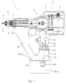
- the single figure shows the rivet setting device according to the invention in a sectional view.
- the rivet setting tool 1 has a housing 2 in which a drive motor 3 is arranged is.
- the drive motor 3 is an electric motor
- the crank drive 5 via a transmission 4 drives with which the rivet setting device 6 is driven.
- the rivet setting device 6 has a traction screw 7, not shown in detail.
- FIG. 1 there is a mouthpiece 8 the rivet setting device is also shown in a sectional view.
- the mouthpiece 8 there is a rivet 9.
- the rivet shown in FIG. 1 has not yet been installed.
- a rivet pin 10 extends into the mouthpiece 8.
- the tension spindle 7 has a passage 11 through which the rivet pin 10 can pass after tearing the inside of the housing 2 of the rivet setting tool 1 falls.
- the housing 2 has a rivet collecting container 12. This is integral with the housing 2 trained.
- the rivet holder 12 has an emptying opening 13 on.
- the housing 2 also has a handle 14 in which a push button switch 15 is included, which can be actuated by a button 16.
- contacts 17 arranged in the handle. The contacts 17 are with the key switch 15 and the motor 3 via electrical lines, not shown, in connection.
- a receptacle 18 is provided, in which a pin-shaped projection 19 one Power supply unit 20 can be used.
- the power supply unit 20 has a housing 21, which also has the projection 19 forms. On the projection 19 of the housing 21 there are also contacts 22 attached, which are in contact with the contacts 17 when the projection 19th is in the receptacle 18.
- Rechargeable batteries are located in the housing 21 of the power supply unit 20, which are not shown in detail. These batteries are with the contacts 22 in Connection. By pressing the key 16 and thus also the key switch 15 the batteries are brought into electrical contact with the motor 3 via the contacts 17 and 22 be so that the motor 3 by the batteries in a known manner with electricity can be supplied.
- the housing 21 of the power supply unit 20 also has a Face 23, which is substantially perpendicular to the longitudinal extension of the projection 19 extends. This end face 23 also forms a cover 24 for the rivet pin receptacle 12th
- This lid 24 also forms a bottom for the rivet holder 12, since the power supply unit 20 below the The rivet holder 12 is arranged.
- the rivet pin receptacle 12 opens out with its Drain opening 13 and the receptacle 18 in a common plane in the Level of the end face 23 of the power supply unit 20 when the power supply unit is plugged in 20 lies.
- the power supply unit 20 is interchangeable and removable on the rivet setting tool 1 attached. You can by simply inserting the projection 19 into the receptacle 18 can be mounted on the rivet setting tool 1. By inserting the contacts 22 and 17 brought into electrical contact. By simply pulling it out Power supply unit 20 can be removed from the rivet setting device 1.
- a partial one Securing device 25 shown with securing brackets ensures that the inserted Power supply unit 20 is not inadvertently removed from the rivet setting tool 1 falls out.
- the power supply unit 20 In order to put the rivet setting tool 1 into operation, the power supply unit 20 is also used its projection 19 is inserted into the receptacle 18. This brings the contacts 22 and 17 in contact.
- the power supply unit 20 can by the in its housing 21st supplied batteries supply the motor 3 with electrical current.
- the rivet holder 12 By inserting the power supply unit 20 into the housing 2 of the rivet setting tool 1, the rivet holder 12 is closed at the same time, in which the Emptying opening 13 is closed by the end face 23. During operation torn rivet pins 10 fall through the passage 11 into the rivet pin receptacle 12. The rivet pins 10 are collected there.
- the rivet pin receptacle 12 is dimensioned so that it is one Amount of rivets 10 can accommodate, which corresponds approximately to the amount of rivets that can be set with the current capacity of the power supply unit 20.
- the rivet setting device ensures that an operable Rivet setting tool, d. H. if the power supply unit 20 is inserted, too at the same time the rivet holder 12 is closed by the lid 24.
- the power supply unit 20 In operational condition, i.e. H. when the power supply unit 20 is in the rivet setting tool 1, it is advantageous that the power supply unit 20 below of the rivet pin receptacle 12 and below the engine 3, the transmission 4, crank mechanism 5 and the rivet setting device 6.
- the handle is between the power supply unit 20 and the motor 3 arranged. Since it is both the power supply unit 20, as well as the engine 3, the transmission 4, the crank mechanism 5 or the Rivet setting device 6 is relatively heavy components, can be in this way better weight distribution of the rivet setting tool 1 above and below the handle Reach 14. This improves the handling of the rivet setting tool 1.
Landscapes
- Engineering & Computer Science (AREA)
- Mechanical Engineering (AREA)
- Portable Nailing Machines And Staplers (AREA)
- Portable Power Tools In General (AREA)
- Insertion Pins And Rivets (AREA)
Abstract
Description
Claims (15)
- Nietsetzgerät mit einer auswechselbar am Nietsetzgerät anbringbaren Stromversorgungseinheit (20), die wenigstens eine vorzugsweise wieder aufladbare Batterie aufweist und mit der durch Anbringen am Nietsetzgerät das Nietsetzgerät (1) in einen betriebsfähigen Zustand überführbar ist, und mit einem Nietstiftauffangbehälter (12), der zumindest eine verschließbare Entleerungsöffnung (13) aufweist, dadurch gekennzeichnet, daß die Stromversorgungseinheit zumindest im betriebsfähigen Zustand einen Deckel (24) bildet, der die Entleerungsöffnung verschließt.
- Nietsetzgerät nach Anspruch 1, dadurch gekennzeichnet, daß das Nietsetzgerät Kontakte (17) aufweist, die im betriebsfähigen Zustand des Nietsetzgerätes mit Kontakten (22) der Stromversorgungseinheit in Verbindung stehen.
- Nietsetzgerät nach Anspruch 1 oder 2, dadurch gekennzeichnet, daß der Nietauffangbehälter (12) einstückig mit einem Gehäuse (2) des Nietsetzgerätes ausgebildet ist.
- Nietsetzgerät nach einem der vorangegangenen Ansprüche, dadurch gekennzeichnet, daß die Stromversorgungseinheit zum Anbringen am Nietsetzgerät in das Gehäuse einsteckbar ist.
- Nietsetzgerät nach einem der vorangegangenen Ansprüche, dadurch gekennzeichnet, daß das Gehäuse einen Griff (14) aufweist und die Stromversorgungseinheit in den Griff einsteckbar ist.
- Nietsetzgerät nach einem der vorangegangenen Ansprüche, dadurch gekennzeichnet, daß der Griff eine Aufnahme (18) aufweist, in welche ein im wesentlichen zapfenförmiger Vorsprung (19) der Stromversorgungseinheit einsteckbar ist.
- Nietsetzgerät nach einem der vorangegangenen Ansprüche, dadurch gekennzeichnet, daß die Stromversorgungseinheit bei Betrieb des Nietsetzgerätes unterhalb des Nietstiftauffangbehälters angeordnet ist.
- Nietsetzgerät nach einem der vorangegangenen Ansprüche, dadurch gekennzeichnet, daß beim Betrieb des Nietsetzgerätes die den Deckel bildende Stromversorgungseinheit wenigstens abschnittsweise den Boden des Nietstiftauffangbehälters bildet.
- Nietsetzgerät nach einem der vorangegangenen Ansprüche, dadurch gekennzeichnet, daß der Deckel durch ein Gehäuse der Stromversorgungsheit gebildet wird.
- Nietsetzgerät nach einem der vorangegangenen Ansprüche, dadurch gekennzeichnet, daß der Nietstiftauffangbehälter beim Betrieb des Nietsetzgerätes unterhalb einer Zugspindel (7) des Nietsetzgerätes angeordnet ist.
- Nietsetzgerät nach einem der vorangegangenen Ansprüche, dadurch gekennzeichnet, daß das Gehäuse als Hohlkörper ausgebildet ist, das den Nietstiftauffangbehälter zumindest abschnittweise begrenzt.
- Nietsetzgerät nach einem der vorangegangenen Ansprüche, dadurch gekennzeichnet, daß das Gehäuse der Stromversorgungseinheit einen Stirnflächenabschnitt aufweist, der den Boden bzw. Deckel bildet und sich im wesentlichen senkrecht zum Vorsprung der Stromversorgungseinheit erstreckt.
- Nietsetzgerät nach einem der vorangegangenen Ansprüche, dadurch gekennzeichnet, daß der Nietstiftauffangbehälter in die Aufnahme mündet.
- Nietsetzgerät nach einem der vorangegangenen Ansprüche, dadurch gekennzeichnet, daß der Nietstiftauffangbehälter und der Griff zur Stromversorgungseinheit hin zusammenlaufen.
- Nietsetzgerät nach einem der vorangegangenen Ansprüche, dadurch gekennzeichnet, daß wenigstens eine Verriegelungseinrichtung vorgesehen ist.
Applications Claiming Priority (2)
| Application Number | Priority Date | Filing Date | Title |
|---|---|---|---|
| DE19806051 | 1998-02-13 | ||
| DE19806051A DE19806051A1 (de) | 1998-02-13 | 1998-02-13 | Nietsetzgerät |
Publications (2)
| Publication Number | Publication Date |
|---|---|
| EP0936006A2 true EP0936006A2 (de) | 1999-08-18 |
| EP0936006A3 EP0936006A3 (de) | 2000-11-29 |
Family
ID=7857704
Family Applications (1)
| Application Number | Title | Priority Date | Filing Date |
|---|---|---|---|
| EP99101151A Withdrawn EP0936006A3 (de) | 1998-02-13 | 1999-01-21 | Nietsetzgerät |
Country Status (6)
| Country | Link |
|---|---|
| US (1) | US6026551A (de) |
| EP (1) | EP0936006A3 (de) |
| JP (1) | JP3235826B2 (de) |
| AU (1) | AU715770B2 (de) |
| BR (1) | BR9900651A (de) |
| DE (1) | DE19806051A1 (de) |
Cited By (2)
| Publication number | Priority date | Publication date | Assignee | Title |
|---|---|---|---|---|
| US6886226B1 (en) | 1999-10-02 | 2005-05-03 | Textron Fastening Systems Limited | Riveting apparatus |
| US10010066B2 (en) | 2014-04-23 | 2018-07-03 | Ridge Tool Company | Hydraulic press tool |
Families Citing this family (10)
| Publication number | Priority date | Publication date | Assignee | Title |
|---|---|---|---|---|
| DE19818757A1 (de) * | 1998-04-27 | 1999-11-04 | Honsel M H Beteiligungs Gmbh | Nietsetzgerät |
| DE19818755A1 (de) * | 1998-04-27 | 1999-11-04 | Honsel M H Beteiligungs Gmbh | Nietsetzgerät |
| DE19903020A1 (de) | 1999-01-26 | 2000-08-03 | Honsel M H Beteiligungs Gmbh | Nietsetzgerät |
| US6383189B1 (en) * | 1999-09-13 | 2002-05-07 | Brian Schumacher | Driver tool for bone distractor with shaft extension |
| US7802352B2 (en) * | 2005-04-13 | 2010-09-28 | Newfrey Llc | Monitoring system for fastener setting tool |
| CN101224487B (zh) * | 2008-01-25 | 2010-07-28 | 孙延新 | 拉铆枪的驱动装置 |
| CN207915402U (zh) | 2018-02-13 | 2018-09-28 | 米沃奇电动工具公司 | 用于铆钉设置工具的鼻夹组 |
| CN219632508U (zh) | 2020-06-03 | 2023-09-05 | 米沃奇电动工具公司 | 用于安置铆钉的铆钉工具及动力工具 |
| CN223507129U (zh) | 2022-07-08 | 2025-11-04 | 米沃奇电动工具公司 | 动力式紧固件驱动器 |
| CN116060570A (zh) * | 2023-03-07 | 2023-05-05 | 峰范新能源汽车技术(太仓)有限公司 | 一种多功能零配件铆接装置 |
Family Cites Families (6)
| Publication number | Priority date | Publication date | Assignee | Title |
|---|---|---|---|---|
| GB1596304A (en) * | 1977-03-22 | 1981-08-26 | Avdel Ltd | Collector for broken-off fastener parts |
| GB2116102A (en) * | 1982-03-08 | 1983-09-21 | Avdel Ltd | Riveting tool |
| US4887450A (en) * | 1988-03-31 | 1989-12-19 | Textron, Inc. | Fastener stem collection apparatus and method |
| FR2677908B1 (fr) * | 1991-06-20 | 1995-04-07 | Hydr Am | Outil autonome polyvalent tel que cisaille/ecarteur a commande hydraulique. |
| DE4126602A1 (de) * | 1991-08-12 | 1993-02-18 | Gesipa Blindniettechnik | Blindnietgeraet |
| US5553478A (en) * | 1994-04-08 | 1996-09-10 | Burndy Corporation | Hand-held compression tool |
-
1998
- 1998-02-13 DE DE19806051A patent/DE19806051A1/de not_active Ceased
-
1999
- 1999-01-21 EP EP99101151A patent/EP0936006A3/de not_active Withdrawn
- 1999-02-11 AU AU16385/99A patent/AU715770B2/en not_active Ceased
- 1999-02-11 US US09/249,245 patent/US6026551A/en not_active Expired - Fee Related
- 1999-02-12 BR BR9900651-0A patent/BR9900651A/pt not_active IP Right Cessation
- 1999-02-15 JP JP03549699A patent/JP3235826B2/ja not_active Expired - Fee Related
Cited By (2)
| Publication number | Priority date | Publication date | Assignee | Title |
|---|---|---|---|---|
| US6886226B1 (en) | 1999-10-02 | 2005-05-03 | Textron Fastening Systems Limited | Riveting apparatus |
| US10010066B2 (en) | 2014-04-23 | 2018-07-03 | Ridge Tool Company | Hydraulic press tool |
Also Published As
| Publication number | Publication date |
|---|---|
| JPH11290983A (ja) | 1999-10-26 |
| AU715770B2 (en) | 2000-02-10 |
| AU1638599A (en) | 1999-09-09 |
| DE19806051A1 (de) | 1999-08-26 |
| BR9900651A (pt) | 2000-01-04 |
| EP0936006A3 (de) | 2000-11-29 |
| US6026551A (en) | 2000-02-22 |
| JP3235826B2 (ja) | 2001-12-04 |
Similar Documents
| Publication | Publication Date | Title |
|---|---|---|
| DE60005074T2 (de) | Batteriebetriebene Handwerkzeugmaschine | |
| DE4038634C2 (de) | ||
| EP0936006A2 (de) | Nietsetzgerät | |
| DE69607906T2 (de) | Batterie Haltungsriegel | |
| DE102005007925B4 (de) | Sauggerät | |
| EP2230164A1 (de) | Fahrradrahmen zur Aufnahme einer Batterieeinheit und zugehörige Batterieeinheit | |
| DE19905086A1 (de) | Batteriegetriebenes, handgeführtes Elektrowerkzeug | |
| DE7521237U (de) | Batteriegetriebenes vielzweckgeraet insbesondere grasschere bohrmaschine u.a. | |
| EP0529266A1 (de) | Elektrisch betriebener Handrührer | |
| EP2521477B1 (de) | Bodenreinigungsgerät | |
| EP0659064B1 (de) | Motorisch betriebenes gerät des persönlichen bedarfs | |
| DE69110503T2 (de) | Deckel mit einem Griff für Gehäuse von Akkumulatoren. | |
| DE3743083A1 (de) | Handstaubsauger | |
| DE19622694B4 (de) | Flurförderzeug mit einem Batteriefach | |
| DE60004240T2 (de) | Elektrisch betriebener handschläger und rührer | |
| DE7625946U1 (de) | Befestigungsvorrichtung zur loesbaren anbringung eines oberen griffes an einer tragbaren, batteriegetriebenen werkzeugmaschine, insbesondere einer grasschere | |
| DE20318187U1 (de) | Elektrischer Dosenöffner | |
| EP1843436B1 (de) | Elektrische Kopplungsanordnung | |
| DE69600114T2 (de) | Motorisierte Gemüse-Presse | |
| EP1293298A2 (de) | Handwerkzeugmaschine mit Staubabsaugung | |
| EP2066202B1 (de) | Küchenmaschine mit schwenkbarem deckel zum abdecken einer kupplungsstelle | |
| DE102020118519A1 (de) | Dickenhobel | |
| DE69311475T2 (de) | Vorrichtung zum Bodenabschaben | |
| DE1248875B (de) | Netzunabhangiges, elektromotorisch angetne benes Handmischgerat | |
| DE102023133045A1 (de) | Arbeitsgerät und Verfahren zu dessen Betrieb |
Legal Events
| Date | Code | Title | Description |
|---|---|---|---|
| PUAI | Public reference made under article 153(3) epc to a published international application that has entered the european phase |
Free format text: ORIGINAL CODE: 0009012 |
|
| AK | Designated contracting states |
Kind code of ref document: A2 Designated state(s): DE ES FR GB IT NL SE |
|
| AX | Request for extension of the european patent |
Free format text: AL;LT;LV;MK;RO;SI |
|
| PUAL | Search report despatched |
Free format text: ORIGINAL CODE: 0009013 |
|
| AK | Designated contracting states |
Kind code of ref document: A3 Designated state(s): AT BE CH CY DE DK ES FI FR GB GR IE IT LI LU MC NL PT SE |
|
| AX | Request for extension of the european patent |
Free format text: AL;LT;LV;MK;RO;SI |
|
| 17P | Request for examination filed |
Effective date: 20001221 |
|
| AKX | Designation fees paid |
Free format text: DE ES FR GB IT NL SE |
|
| GRAH | Despatch of communication of intention to grant a patent |
Free format text: ORIGINAL CODE: EPIDOS IGRA |
|
| STAA | Information on the status of an ep patent application or granted ep patent |
Free format text: STATUS: THE APPLICATION IS DEEMED TO BE WITHDRAWN |
|
| 18D | Application deemed to be withdrawn |
Effective date: 20030911 |