EP0934870A2 - Crampon d'assemblage d'un garde-boue pour bicyclette avec une tringle de support - Google Patents
Crampon d'assemblage d'un garde-boue pour bicyclette avec une tringle de support Download PDFInfo
- Publication number
- EP0934870A2 EP0934870A2 EP99101296A EP99101296A EP0934870A2 EP 0934870 A2 EP0934870 A2 EP 0934870A2 EP 99101296 A EP99101296 A EP 99101296A EP 99101296 A EP99101296 A EP 99101296A EP 0934870 A2 EP0934870 A2 EP 0934870A2
- Authority
- EP
- European Patent Office
- Prior art keywords
- mudguard
- branches
- support rod
- fastening device
- clamp
- Prior art date
- Legal status (The legal status is an assumption and is not a legal conclusion. Google has not performed a legal analysis and makes no representation as to the accuracy of the status listed.)
- Granted
Links
Images
Classifications
-
- B—PERFORMING OPERATIONS; TRANSPORTING
- B62—LAND VEHICLES FOR TRAVELLING OTHERWISE THAN ON RAILS
- B62J—CYCLE SADDLES OR SEATS; AUXILIARY DEVICES OR ACCESSORIES SPECIALLY ADAPTED TO CYCLES AND NOT OTHERWISE PROVIDED FOR, e.g. ARTICLE CARRIERS OR CYCLE PROTECTORS
- B62J15/00—Mud-guards for wheels
- B62J15/02—Fastening means; Stays
Definitions
- the invention relates to an improved device for fixing a mudguard bicycle on the support rods which are normally secured to the fork of the frame and means of the wheel associated with said mudguard.
- the support element consists of two separate parts between which the support rods are blocked, and which are held together by means of the traditional screw and nut assembly or, when made of plastic, by means of self-tapping screws.
- This system has the disadvantage of complicating the general assembly of the mudguard and, thereby increasing manufacturing costs.
- EP-A-0 742 137 which overcomes this drawback, includes a plastic support element which has a slot inside which a portion of the edge of the mudguard attached to this element and one or two holes are inserted for the passage of the single support rod or two support rods.
- This element is further provided with a through hole arranged substantially perpendicular to the aforementioned holes, where a self-tapping screw is inserted who by tightening, deforms said element made of plastic, thereby also obtaining well the clamping of the mudguard as the final fixing of the rods on said element.
- the purpose of the present invention is to provide an assembly device between the mudguard and rigid support rod that is able to create a stable assembly over time, to withstand the normal stresses to which the mudguard East submitted and, at the same time, allow immediate and automatic answer in response abnormal loads such as, for example, the accidental introduction of a pebble between the wheel and the mudguard or similar causes.
- the device according to the invention to give total security of operation, provides for three different dropout modes and, more precisely, the exhaust of the portion of the mudguard in contact with the support element, or the deformation of the support element, made of plastic and, finally, the sliding of said element on the support rod until its complete release by compared to it.
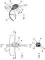
- the device according to the invention acts as an assembly between the mudguard 2 and the support rod 3.
- the stud 1 comprises two branches 4 and 5, arranged substantially symmetrical, and held together at their bottom, by a tongue flexible 6, which allows them to be folded over each other so as to form the spouts pliers which, once closed, hook portion 7 of the mudguard between them 1, thereby achieving the desired attachment.
- the upper ends 8 and 9 of the branches 4 and 5 are shaped so as to match the interior profile respectively and the external profile of the retained portion 7.
- one of the two ends upper preferably the one placed in the inner part of the mudguard, East provided with a protruding boss 10, roughly hemispherical and which, when the clamp is mounted, will fit into a corresponding hole in part 7 of the mudguard in contact with the crampon.
- a cavity is formed longitudinal in which a portion of the support rod 3 is placed.
- the stud 1 is pierced with a hole 11, substantially perpendicular to said cavity longitudinal insertion of the support rod 3, into which a screw is inserted self-tapping 12 which, once inserted and screwed, provides, by deformation of the plastic material in which the crampon is made, to hold the branches 4 and 5 close to each other and, at the same time, to block the support rod 3 in the retaining cavity.
- the head 13 of the self-tapping screw 12 in addition to being housed in a seat formed on the body of one of the two branches, 4 or 5, preferably the one placed outside the mudguard, press a elastic element 14, preferably a washer, which makes it possible to maintain in the time an adequate clamp closure tension and, at the same time, may fail to allow possible opening of said clamp in the event of a stress unexpected pullout.
- the support rod 3 is inserted into the corresponding longitudinal cavity and, finally, then, we proceed to the screwing of the self-tapping screw 12 which causes the closing the crampon, blocking the mudguard on it as well above that support rod itself.
- a first dropout mode that occurs when there is a demand abnormal fast and high intensity, is achieved by the exhaust of the mudguard through relative to the protruding boss 10.
- a second stall mode which occurs when the mudguard is subjected to an abnormal request of strong intensity but applied slowly, is carried out by the deformation of the entire clamp and, in particular, of the elastic element 14 in washer shape, allowing the mudguard to clear of the protruding boss 10.
- a third type of dropout which occurs in the event or both previous processes have not intervened, consists in the possibility that the clamp 1, under the action of stress 15, to slide on the support rod 3 just to be completely free of the latter.
Abstract
Description
Claims (11)
- Dispositif de fixation d'un garde-boue de bicyclette à des tringles de support solidaires de la fourche du cadre, ou du moyeu de la roue associée audit garde-boue, ledit dispositif étant caractérisé par le fait qu'il comprend un crampon (1), qui joue le rôle de liaison entre le garde-boue (2) et la tringle de support (3), ledit crampon comprenant deux branches (4, 5), disposées de façon sensiblement symétrique, et tenues réunies l'une à l'autre, dans leur partie inférieure, par une languette flexible (6), ce qui permet de les replier l'une sur l'autre de manière à former les becs d'une pince qui, une fois refermés, viennent accrocher entre eux une portion (7) dudit garde-boue, en réalisant de cette façon l'accrochage.
- Dispositif de fixation selon la revendication 1, caractérisé par le fait que les extrémités supérieures (8, 9) des branches (4, 5) sont conformées de manière à épouser respectivement le profil intérieur et le profil extérieur de la portion (7) du garde-boue.
- Dispositif de fixation selon l'une des revendications 1 ou 2, caractérisé par le fait qu'une des deux extrémités supérieures (8, 9) des branches (4, 5), de préférence celle (8) placée dans la partie intérieure du garde-boue, est munie d'un bossage saillant (10) adapté pour'se loger, lorsque le crampon est monté, dans un trou correspondant ménagé sur la portion (7) du garde-boue qui est en contact avec la crampon.
- Dispositif de fixation selon une ou plusieurs des revendications précédentes, caractérisé par le fait que, dans la zone intérieure de contact entre les deux branches (4, 5) est ménagée au moins une cavité longitudinale d'insertion d'une portion d'au moins une tringle de support (3).
- Dispositif de fixation selon une ou plusieurs des revendications précédentes, caractérisé par le fait que, dans le crampon (1), est formé un trou (11), sensiblement perpendiculaire aux cavités longitudinales d'insertion des tringles de support (3), trou (11) de réception d'une vis auto-taraudeuse (12) qui, un fois introduite et vissée, pourvoit, par déformation de la matière dont ledit crampon est formé, à maintenir les branches (4, 5) rapprochées l'une de l'autres et, en même temps, à bloquer chaque tringle précitée dans la cavité de retenue correspondante.
- Dispositif de fixation selon une ou plusieurs des revendications précédentes, caractérisé par le fait que la tête (13) de la vis auto-taraudeuse (12) est logée dans un siège formé sur le corps d'une des deux branches (4, 5), de préférence de celle placée à l'extérieur du garde-boue et appuie sur un élément élastique (14), de préférence une rondelle, laquelle permet de maintenir dans le temps un tension adéquate de fermeture du crampon.
- Dispositif de fixation selon une ou plusieurs des revendications précédentes, caractérisé en ce qu'il comprend en outre un assemblage à vis avec écrou pour maintenir les branches (4, 5) rapprochées l'une de l'autre et, en même temps, pour bloquer chaque tringle de support (3) dans la cavité de retenue correspondante.
- Dispositif de fixation selon une ou plusieurs des revendications 1 à 6, caractérisé en ce qu'il comprend en outre un assemblage à agrafe pour maintenir les branches (4, 5) rapprochées l'une de l'autre et, en même temps, pour bloquer chaque tringle de support (3) dans la cavité de retenue correspondante.
- Utilisation du dispositif pour la fixation d'un garde-boue de bicyclette aux tringles de support, décrit dans une ou plusieurs des revendications précédentes, caractérisé par le fait que, lorsqu'une sollicitation anormale (15) vient intéresser le corps du garde-boue (1), ladite force peut provoquer le décrochage du garde-boue par l'échappement de ce dernier par rapport au bossage saillant (10).
- Utilisation du dispositif pour la fixation d'un garde-boue de bicylclette aux tringles de support, décrit dans une ou plusieurs des revendications précédentes, caractérisé par le fait que, lorsqu'une sollicitation anormale (15) vient intéresser le corps du garde-boue (2), ladite force peut provoquer le décrochage du garde-boue à cause de la déformation de tout le crampon (1) et, en particulier, de l'élément élastique en forme de rondelle (14), en permettant alors au garde-boue de se dégager du bossage saillant (10).
- Utilisation du dispositif pour la fixation d'un garde-boue de bicyclette aux tringles de support, décrit dans une ou plusieurs des revendications précédentes, caractérisé par le fait que, lorsqu'une sollicitation anormale (15) vient intéresser le corps du garde-boue (1), ladite force peut provoquer le décrochage du garde-boue par suite du coulissement du crampon (1) sur la tringle de support (3), jusqu'à son dégagement complet par rapport à celle-ci.
Applications Claiming Priority (2)
| Application Number | Priority Date | Filing Date | Title |
|---|---|---|---|
| ITVI980018 | 1998-02-04 | ||
| ITVI980018 ITVI980018A1 (it) | 1998-02-04 | 1998-02-04 | Norsetto di collegamento parafango per biciclette - aste di supporto con triplice sicurezza di sgancio automatico in caso di sollecitazioni |
Publications (3)
| Publication Number | Publication Date |
|---|---|
| EP0934870A2 true EP0934870A2 (fr) | 1999-08-11 |
| EP0934870A3 EP0934870A3 (fr) | 2000-05-03 |
| EP0934870B1 EP0934870B1 (fr) | 2005-10-05 |
Family
ID=11426566
Family Applications (1)
| Application Number | Title | Priority Date | Filing Date |
|---|---|---|---|
| EP19990101296 Expired - Lifetime EP0934870B1 (fr) | 1998-02-04 | 1999-01-25 | Crampon d'assemblage d'un garde-boue pour bicyclette avec une tringle de support |
Country Status (3)
| Country | Link |
|---|---|
| EP (1) | EP0934870B1 (fr) |
| DE (1) | DE69927536T2 (fr) |
| IT (1) | ITVI980018A1 (fr) |
Cited By (4)
| Publication number | Priority date | Publication date | Assignee | Title |
|---|---|---|---|---|
| WO2003022669A1 (fr) * | 2001-09-13 | 2003-03-20 | San Giorgio Bicycle Components Srl | Dispositif de fixation d'un garde-boue de bicyclette comprenant deux elements interconnectes |
| NL1022857C2 (nl) * | 2003-03-06 | 2004-09-09 | Lepper Beheer B V | Koppeling, systeem en fiets. |
| FR2852290A1 (fr) * | 2003-03-14 | 2004-09-17 | Honda Motor Co Ltd | Structure de montage de garde-boue avant |
| EP1468902A2 (fr) | 2003-04-16 | 2004-10-20 | Rpz S.R.L. | Dispositif d'attache pour un garde-boue de bicyclette |
Citations (2)
| Publication number | Priority date | Publication date | Assignee | Title |
|---|---|---|---|---|
| GB2278323A (en) | 1993-05-25 | 1994-11-30 | Webb Ronald R | Fixing stays to mudguards |
| EP0742137A2 (fr) | 1995-05-11 | 1996-11-13 | ZINCATURA SAN GIORGIO s.n.c. di DE POLI GAVINO & C. | Dispositif pour la fixation d'un garde-boue de bicyclette |
-
1998
- 1998-02-04 IT ITVI980018 patent/ITVI980018A1/it unknown
-
1999
- 1999-01-25 EP EP19990101296 patent/EP0934870B1/fr not_active Expired - Lifetime
- 1999-01-25 DE DE69927536T patent/DE69927536T2/de not_active Expired - Fee Related
Patent Citations (2)
| Publication number | Priority date | Publication date | Assignee | Title |
|---|---|---|---|---|
| GB2278323A (en) | 1993-05-25 | 1994-11-30 | Webb Ronald R | Fixing stays to mudguards |
| EP0742137A2 (fr) | 1995-05-11 | 1996-11-13 | ZINCATURA SAN GIORGIO s.n.c. di DE POLI GAVINO & C. | Dispositif pour la fixation d'un garde-boue de bicyclette |
Cited By (5)
| Publication number | Priority date | Publication date | Assignee | Title |
|---|---|---|---|---|
| WO2003022669A1 (fr) * | 2001-09-13 | 2003-03-20 | San Giorgio Bicycle Components Srl | Dispositif de fixation d'un garde-boue de bicyclette comprenant deux elements interconnectes |
| NL1022857C2 (nl) * | 2003-03-06 | 2004-09-09 | Lepper Beheer B V | Koppeling, systeem en fiets. |
| FR2852290A1 (fr) * | 2003-03-14 | 2004-09-17 | Honda Motor Co Ltd | Structure de montage de garde-boue avant |
| EP1468902A2 (fr) | 2003-04-16 | 2004-10-20 | Rpz S.R.L. | Dispositif d'attache pour un garde-boue de bicyclette |
| EP1468902A3 (fr) * | 2003-04-16 | 2007-07-25 | Rpz S.R.L. | Dispositif d'attache pour un garde-boue de bicyclette |
Also Published As
| Publication number | Publication date |
|---|---|
| DE69927536T2 (de) | 2006-07-06 |
| EP0934870B1 (fr) | 2005-10-05 |
| ITVI980018A1 (it) | 1999-08-04 |
| EP0934870A3 (fr) | 2000-05-03 |
| DE69927536D1 (de) | 2005-11-10 |
Similar Documents
| Publication | Publication Date | Title |
|---|---|---|
| EP0334688B1 (fr) | Dispositif de fixation perfectionnée formant pince et pièce quelconque munie de ce dispositif | |
| EP2121422B1 (fr) | Pedale de bicyclette a enclenchement et declenchement automatiques | |
| FR2716422A1 (fr) | Dispositif de fixation d'un cycle pour un porte-cycle et porte-cycle comprenant un tel dispositif. | |
| EP1787878B1 (fr) | Dispositif de montage notamment d'une tige de commande de frein sur la pédale de frein d'un véhicule automobile | |
| EP0130896B1 (fr) | Dispositif de fixation d'un accessoire sur un cycle | |
| EP1112703B1 (fr) | Pince à cheveux à ressort masqué | |
| FR2649454A1 (fr) | Ecrou en forme de pince a montage sur le bord d'un panneau ou analogue | |
| EP0934870A2 (fr) | Crampon d'assemblage d'un garde-boue pour bicyclette avec une tringle de support | |
| EP0544376B1 (fr) | Attache de fixation d'une pièce munie d'une tige sur une paroi | |
| EP0754868B1 (fr) | Attache pour la fixation réglable de deux pièces espacées | |
| FR2494788A1 (fr) | Attache pour l'assemblage d'elements plats a angle droit | |
| FR2613813A1 (fr) | Collier de serrage pour embout tubulaire | |
| EP0326481A1 (fr) | Ecrou en forme de pince et assemblage réalisé à l'aide de cet écrou | |
| EP0358565A2 (fr) | Dispositif de tuteurage pour végétaux | |
| EP2998208A1 (fr) | Dispositif de maintien d'un fourreau de protection d'une main sur la poignée d'un guidon de motocycle | |
| EP0679783B1 (fr) | Attache à montage pivotant sur un élément quelconque | |
| EP0775507B1 (fr) | Fixation de ski équipée d'un frein démontable | |
| EP0428436A1 (fr) | Couteau d'étrivière pour selle de cheval | |
| EP1323881A2 (fr) | Poignée de véhicule automobile, en particulier pour une portière latérale | |
| FR2786233A1 (fr) | Dispositif de liaison pour levier pivotant, notamment pedale de frein, et organe de commande associe | |
| EP0209479B1 (fr) | Antivol pour véhicules automobiles | |
| FR2647842A1 (fr) | Perfectionnement aux espagnolettes | |
| FR2544411A1 (fr) | Dispositif de fixation a ecrou retenu en une seule piece | |
| EP0964125A1 (fr) | Curseur de support de vitre dans un lève-vitre de porte de véhicule | |
| FR3052114A1 (fr) | Ensemble d’une sangle et de son dispositif de pre-maintien d’un reservoir de carburant d’un vehicule automobile |
Legal Events
| Date | Code | Title | Description |
|---|---|---|---|
| PUAI | Public reference made under article 153(3) epc to a published international application that has entered the european phase |
Free format text: ORIGINAL CODE: 0009012 |
|
| AK | Designated contracting states |
Kind code of ref document: A2 Designated state(s): BE DE DK ES FI FR GB IT NL SE |
|
| AX | Request for extension of the european patent |
Free format text: AL;LT;LV;MK;RO;SI |
|
| PUAL | Search report despatched |
Free format text: ORIGINAL CODE: 0009013 |
|
| AK | Designated contracting states |
Kind code of ref document: A3 Designated state(s): AT BE CH CY DE DK ES FI FR GB GR IE IT LI LU MC NL PT SE |
|
| AX | Request for extension of the european patent |
Free format text: AL;LT;LV;MK;RO;SI |
|
| 17P | Request for examination filed |
Effective date: 20001012 |
|
| AKX | Designation fees paid |
Free format text: BE DE DK ES FI FR GB IT NL SE |
|
| 17Q | First examination report despatched |
Effective date: 20040414 |
|
| GRAP | Despatch of communication of intention to grant a patent |
Free format text: ORIGINAL CODE: EPIDOSNIGR1 |
|
| GRAS | Grant fee paid |
Free format text: ORIGINAL CODE: EPIDOSNIGR3 |
|
| GRAP | Despatch of communication of intention to grant a patent |
Free format text: ORIGINAL CODE: EPIDOSNIGR1 |
|
| GRAF | Information related to payment of grant fee modified |
Free format text: ORIGINAL CODE: EPIDOSCIGR3 |
|
| GRAA | (expected) grant |
Free format text: ORIGINAL CODE: 0009210 |
|
| AK | Designated contracting states |
Kind code of ref document: B1 Designated state(s): BE DE DK ES FI FR GB IT NL SE |
|
| PG25 | Lapsed in a contracting state [announced via postgrant information from national office to epo] |
Ref country code: GB Free format text: LAPSE BECAUSE OF FAILURE TO SUBMIT A TRANSLATION OF THE DESCRIPTION OR TO PAY THE FEE WITHIN THE PRESCRIBED TIME-LIMIT Effective date: 20051005 Ref country code: FI Free format text: LAPSE BECAUSE OF FAILURE TO SUBMIT A TRANSLATION OF THE DESCRIPTION OR TO PAY THE FEE WITHIN THE PRESCRIBED TIME-LIMIT Effective date: 20051005 |
|
| REG | Reference to a national code |
Ref country code: GB Ref legal event code: FG4D Free format text: NOT ENGLISH |
|
| REF | Corresponds to: |
Ref document number: 69927536 Country of ref document: DE Date of ref document: 20051110 Kind code of ref document: P |
|
| PG25 | Lapsed in a contracting state [announced via postgrant information from national office to epo] |
Ref country code: SE Free format text: LAPSE BECAUSE OF FAILURE TO SUBMIT A TRANSLATION OF THE DESCRIPTION OR TO PAY THE FEE WITHIN THE PRESCRIBED TIME-LIMIT Effective date: 20060105 Ref country code: DK Free format text: LAPSE BECAUSE OF FAILURE TO SUBMIT A TRANSLATION OF THE DESCRIPTION OR TO PAY THE FEE WITHIN THE PRESCRIBED TIME-LIMIT Effective date: 20060105 |
|
| PG25 | Lapsed in a contracting state [announced via postgrant information from national office to epo] |
Ref country code: ES Free format text: LAPSE BECAUSE OF FAILURE TO SUBMIT A TRANSLATION OF THE DESCRIPTION OR TO PAY THE FEE WITHIN THE PRESCRIBED TIME-LIMIT Effective date: 20060116 |
|
| PG25 | Lapsed in a contracting state [announced via postgrant information from national office to epo] |
Ref country code: FR Free format text: LAPSE BECAUSE OF NON-PAYMENT OF DUE FEES Effective date: 20060131 Ref country code: BE Free format text: LAPSE BECAUSE OF NON-PAYMENT OF DUE FEES Effective date: 20060131 |
|
| PGFP | Annual fee paid to national office [announced via postgrant information from national office to epo] |
Ref country code: IT Payment date: 20060131 Year of fee payment: 8 |
|
| GBV | Gb: ep patent (uk) treated as always having been void in accordance with gb section 77(7)/1977 [no translation filed] |
Effective date: 20051005 |
|
| PLBE | No opposition filed within time limit |
Free format text: ORIGINAL CODE: 0009261 |
|
| STAA | Information on the status of an ep patent application or granted ep patent |
Free format text: STATUS: NO OPPOSITION FILED WITHIN TIME LIMIT |
|
| 26N | No opposition filed |
Effective date: 20060706 |
|
| REG | Reference to a national code |
Ref country code: FR Ref legal event code: ST Effective date: 20060929 |
|
| PGFP | Annual fee paid to national office [announced via postgrant information from national office to epo] |
Ref country code: NL Payment date: 20061215 Year of fee payment: 9 |
|
| PGFP | Annual fee paid to national office [announced via postgrant information from national office to epo] |
Ref country code: DE Payment date: 20070327 Year of fee payment: 9 |
|
| BERE | Be: lapsed |
Owner name: *PASSUELLO IVAN Effective date: 20060131 Owner name: *PASSUELLO MICHELE Effective date: 20060131 |
|
| NLV4 | Nl: lapsed or anulled due to non-payment of the annual fee |
Effective date: 20080801 |
|
| PG25 | Lapsed in a contracting state [announced via postgrant information from national office to epo] |
Ref country code: NL Free format text: LAPSE BECAUSE OF NON-PAYMENT OF DUE FEES Effective date: 20080801 Ref country code: DE Free format text: LAPSE BECAUSE OF NON-PAYMENT OF DUE FEES Effective date: 20080801 |
|
| PG25 | Lapsed in a contracting state [announced via postgrant information from national office to epo] |
Ref country code: IT Free format text: LAPSE BECAUSE OF NON-PAYMENT OF DUE FEES Effective date: 20070125 |