EP0934870A2 - Mounting clamp for a bicycle mudguard with a support rod - Google Patents
Mounting clamp for a bicycle mudguard with a support rod Download PDFInfo
- Publication number
- EP0934870A2 EP0934870A2 EP99101296A EP99101296A EP0934870A2 EP 0934870 A2 EP0934870 A2 EP 0934870A2 EP 99101296 A EP99101296 A EP 99101296A EP 99101296 A EP99101296 A EP 99101296A EP 0934870 A2 EP0934870 A2 EP 0934870A2
- Authority
- EP
- European Patent Office
- Prior art keywords
- mudguard
- branches
- support rod
- fastening device
- clamp
- Prior art date
- Legal status (The legal status is an assumption and is not a legal conclusion. Google has not performed a legal analysis and makes no representation as to the accuracy of the status listed.)
- Granted
Links
Images
Classifications
-
- B—PERFORMING OPERATIONS; TRANSPORTING
- B62—LAND VEHICLES FOR TRAVELLING OTHERWISE THAN ON RAILS
- B62J—CYCLE SADDLES OR SEATS; AUXILIARY DEVICES OR ACCESSORIES SPECIALLY ADAPTED TO CYCLES AND NOT OTHERWISE PROVIDED FOR, e.g. ARTICLE CARRIERS OR CYCLE PROTECTORS
- B62J15/00—Mud-guards for wheels
- B62J15/02—Fastening means; Stays
Definitions
- the invention relates to an improved device for fixing a mudguard bicycle on the support rods which are normally secured to the fork of the frame and means of the wheel associated with said mudguard.
- the support element consists of two separate parts between which the support rods are blocked, and which are held together by means of the traditional screw and nut assembly or, when made of plastic, by means of self-tapping screws.
- This system has the disadvantage of complicating the general assembly of the mudguard and, thereby increasing manufacturing costs.
- EP-A-0 742 137 which overcomes this drawback, includes a plastic support element which has a slot inside which a portion of the edge of the mudguard attached to this element and one or two holes are inserted for the passage of the single support rod or two support rods.
- This element is further provided with a through hole arranged substantially perpendicular to the aforementioned holes, where a self-tapping screw is inserted who by tightening, deforms said element made of plastic, thereby also obtaining well the clamping of the mudguard as the final fixing of the rods on said element.
- the purpose of the present invention is to provide an assembly device between the mudguard and rigid support rod that is able to create a stable assembly over time, to withstand the normal stresses to which the mudguard East submitted and, at the same time, allow immediate and automatic answer in response abnormal loads such as, for example, the accidental introduction of a pebble between the wheel and the mudguard or similar causes.
- the device according to the invention to give total security of operation, provides for three different dropout modes and, more precisely, the exhaust of the portion of the mudguard in contact with the support element, or the deformation of the support element, made of plastic and, finally, the sliding of said element on the support rod until its complete release by compared to it.
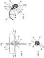
- the device according to the invention acts as an assembly between the mudguard 2 and the support rod 3.
- the stud 1 comprises two branches 4 and 5, arranged substantially symmetrical, and held together at their bottom, by a tongue flexible 6, which allows them to be folded over each other so as to form the spouts pliers which, once closed, hook portion 7 of the mudguard between them 1, thereby achieving the desired attachment.
- the upper ends 8 and 9 of the branches 4 and 5 are shaped so as to match the interior profile respectively and the external profile of the retained portion 7.
- one of the two ends upper preferably the one placed in the inner part of the mudguard, East provided with a protruding boss 10, roughly hemispherical and which, when the clamp is mounted, will fit into a corresponding hole in part 7 of the mudguard in contact with the crampon.
- a cavity is formed longitudinal in which a portion of the support rod 3 is placed.
- the stud 1 is pierced with a hole 11, substantially perpendicular to said cavity longitudinal insertion of the support rod 3, into which a screw is inserted self-tapping 12 which, once inserted and screwed, provides, by deformation of the plastic material in which the crampon is made, to hold the branches 4 and 5 close to each other and, at the same time, to block the support rod 3 in the retaining cavity.
- the head 13 of the self-tapping screw 12 in addition to being housed in a seat formed on the body of one of the two branches, 4 or 5, preferably the one placed outside the mudguard, press a elastic element 14, preferably a washer, which makes it possible to maintain in the time an adequate clamp closure tension and, at the same time, may fail to allow possible opening of said clamp in the event of a stress unexpected pullout.
- the support rod 3 is inserted into the corresponding longitudinal cavity and, finally, then, we proceed to the screwing of the self-tapping screw 12 which causes the closing the crampon, blocking the mudguard on it as well above that support rod itself.
- a first dropout mode that occurs when there is a demand abnormal fast and high intensity, is achieved by the exhaust of the mudguard through relative to the protruding boss 10.
- a second stall mode which occurs when the mudguard is subjected to an abnormal request of strong intensity but applied slowly, is carried out by the deformation of the entire clamp and, in particular, of the elastic element 14 in washer shape, allowing the mudguard to clear of the protruding boss 10.
- a third type of dropout which occurs in the event or both previous processes have not intervened, consists in the possibility that the clamp 1, under the action of stress 15, to slide on the support rod 3 just to be completely free of the latter.
Abstract
Description
L'invention concerne un dispositif perfectionné pour la fixation d'un garde-boue de bicyclette sur les tringles de support qui sont normalement solidaires de la fourche du cadre et du moyen de la roue associé audit garde-boue.The invention relates to an improved device for fixing a mudguard bicycle on the support rods which are normally secured to the fork of the frame and means of the wheel associated with said mudguard.
On connaít de nombreux dispositifs aptes à assembler le garde-boue aux tringles de support ; à titre d'exemple, on cite les documents GB-A-2 278 323 et EP-A-0 742 137 qui constituent l'état de la technique le plus proche de la présente invention.We know many devices capable of assembling the mudguard to the rods support; by way of example, the documents GB-A-2 278 323 and EP-A-0 are cited 742 137 which constitute the state of the art closest to the present invention.
Dans le document GB-A-2 278 323, la fixation du garde-boue est réalisée en utilisant pour chaque tringle ou pour une paire de tringles parallèles un élément de support métallique ou en matière plastique qui est fixé au garde-boue au moyen de rivets ou d'autres moyens mécaniques, placés au droit du bord extérieur du garde-boue.In document GB-A-2 278 323, the fixing of the mudguard is carried out in using for each rod or for a pair of parallel rods an element of metal or plastic support which is fixed to the mudguard by means of rivets or other mechanical means, placed to the right of the outer edge of the mudguard.
L'élément de support est constitué par deux parties distinctes entre lesquelles les tringles du support sont bloquées, et qui sont maintenues réunies au moyen du traditionnel assemblage à vis et écrou ou, lorsqu'elles sont réalisées en matière plastique, au moyen de vis auto-taraudeuses.The support element consists of two separate parts between which the support rods are blocked, and which are held together by means of the traditional screw and nut assembly or, when made of plastic, by means of self-tapping screws.
Ce système a l'inconvénient de compliquer le montage général du garde-boue et, de ce fait, d'augmenter les coûts de fabrication.This system has the disadvantage of complicating the general assembly of the mudguard and, thereby increasing manufacturing costs.
Le document EP-A- 0 742 137, qui résout cet inconvénient, comprend un élément de support en matière plastique qui présente une fente à l'intérieur de laquelle est insérée une portion du bord du garde-boue fixé à cet élément et un ou deux trous pour le passage de l'unique tringle de support ou des deux tringles de support.EP-A-0 742 137, which overcomes this drawback, includes a plastic support element which has a slot inside which a portion of the edge of the mudguard attached to this element and one or two holes are inserted for the passage of the single support rod or two support rods.
Cet élément est en outre muni d'un trou de passage disposé sensiblement perpendiculairement aux trous précités, où est insérée une vis auto-taraudeuse qui, par son serrage, déforme ledit élément réalisé en matière plastique, en obtenant ainsi aussi bien l'enserrage du garde-boue que la fixation définitive des tringles sur ledit élément. This element is further provided with a through hole arranged substantially perpendicular to the aforementioned holes, where a self-tapping screw is inserted who by tightening, deforms said element made of plastic, thereby also obtaining well the clamping of the mudguard as the final fixing of the rods on said element.
Ces deux dispositifs, comme d'autres qui sont connus dans l'état de la technique, bien qu'ils assurent un assemblage suffisamment rigide du garde-boue aux tringles de support, de manière à pouvoir résister aux sollicitations normales, présentent l'inconvénient de ne pas permettre un décrochage immédiat du garde-boue de son élément de support en présence de sollicitations anormales et d'intensité de nature à rendre dangereuse une éventuelle rigidité excessive de l'assemblage garde-boue-tringle de support.These two devices, like others which are known in the state of the art, although they ensure a sufficiently rigid assembly of the mudguard to the rods of support, so as to be able to withstand normal stresses, present the disadvantage of not allowing an immediate stall of the mudguard from its support element in the presence of abnormal stresses and intensity likely to make it dangerous to have excessive rigidity in the fender-rod assembly of support.
Le but de la présente invention est de réaliser un dispositif d'assemblage entre le garde-boue et la tringle de support rigide qui soit propre à créer un assemblage stable dans le temps, pour résister aux sollicitations normales auxquelles le garde-boue est soumis et, en même temps, permettre le décrochage immédiat et automatique en réponse à des sollicitations anormales comme, par exemple, l'introduction accidentelle d'un caillou entre la roue et la garde-boue ou à d'autres causes analogues.The purpose of the present invention is to provide an assembly device between the mudguard and rigid support rod that is able to create a stable assembly over time, to withstand the normal stresses to which the mudguard East submitted and, at the same time, allow immediate and automatic answer in response abnormal loads such as, for example, the accidental introduction of a pebble between the wheel and the mudguard or similar causes.
Ceci est obtenue conformément aux caractéristiques de la partie caractérisante de la revendication 1.This is achieved in accordance with the characteristics of the characterizing part of claim 1.
En détail, le dispositif selon l'invention, pour donner la totale sécurité de fonctionnement, prévoit trois différents modes de décrochage et, plus précisément, l'échappement de la portion du garde-boue en contact avec l'élément de support, ou la déformation de l'élément de support, réalisé en matière plastique et, finalement, le coulissement dudit élément sur la tringle de support jusqu'à son complet dégagement par rapport à celle-ci.In detail, the device according to the invention, to give total security of operation, provides for three different dropout modes and, more precisely, the exhaust of the portion of the mudguard in contact with the support element, or the deformation of the support element, made of plastic and, finally, the sliding of said element on the support rod until its complete release by compared to it.
D'autres avantages et caractéristiques de l'invention ressortent plus clairement de
la description d'une forme possible de réalisation, donnée uniquement à titre d'exemple
illustratif et non limitatif, au moyen de la planche de dessins annexée sur laquelle :
Comme on peut le voir sur les Figures, le dispositif selon l'invention, défini dans
ce qui suit par le nom de crampon 1, fait office d'assemblage entre le garde-boue
2 et la
tringle de support 3.As can be seen in the Figures, the device according to the invention, defined in
the following by the name of stud 1, acts as an assembly between the
La crampon 1 comprend deux branches 4 et 5, disposées de façon sensiblement
symétrique, et tenues réunies l'une à l'autre, dans leur partie inférieure, par une languette
flexible 6, ce qui permet de les replier l'une sur l'autre de manière à former les becs
d'une pince qui, une fois refermés, viennent accrocher entre eux la portion 7 du garde-boue
1, en réalisant de cette façon l'accrochage voulu.The stud 1 comprises two
Pour rendre cet accrochage plus solidaire, les extrémités supérieures 8 et 9 des
branches 4 et 5 sont conformées de manière à épouser respectivement le profil intérieur
et le profil extérieur de la portion 7 retenue.To make this attachment more integral, the
Toujours pour rendre ledit accrochage plus solidaire, une des deux extrémités
supérieures, de préférence celle qui est placée dans la partie intérieure du garde-boue,
est
munie d'un bossage saillant 10, à peu près hémisphérique et qui, lorsque le crampon est
monté, va se loger dans un trou correspondant ménagé dans la partie 7 du garde-boue
en
contact avec le crampon.Always to make said attachment more secure, one of the two ends
upper, preferably the one placed in the inner part of the mudguard,
East
provided with a
Dans la zone intérieure de contact entre les deux branches, est formée une cavité longitudinale dans laquelle trouve place une portion de la tringle de support 3. In the inner zone of contact between the two branches, a cavity is formed longitudinal in which a portion of the support rod 3 is placed.
Le crampon 1 est percé d'un trou 11, sensiblement perpendiculaire à ladite cavité
longitudinale d'insertion de la tringle du support 3, dans laquelle vient s'insérer une vis
auto-taraudeuse 12 qui, une fois introduite et vissée, pourvoit, par déformation de la
matière plastique dans laquelle le crampon est réalisé, à maintenir les branches 4 et 5
rapprochées l'une de l'autre et, en même temps, à bloquer la tringle de support 3 dans la
cavité de retenue. :The stud 1 is pierced with a
Finalement, il est avantageusement prévu que la tête 13 de la vis auto-taraudeuse
12, en supplément d'être logée dans un siège formé sur le corps d'une des deux
branches, 4 ou 5, de préférence de celle placée à l'extérieur de garde-boue,
appuie sur un
élément élastique 14, de préférence une rondelle, lequel permet de maintenir dans le
temps une tension adéquate de fermeture de crampon et, en même temps, peut céder
pour permettre une éventuelle ouverture dudit crampon dans le cas d'une sollicitation
d'arrachage inattendue.Finally, it is advantageously provided that the
Fonctionnellement, après que les deux branches 4 et 5 ont été repliées de manière
que le bossage saillant 10 soit logé dans le trou correspondant ménagé sur le garde-boue,
on insère la tringle de support 3 dans la cavité longitudinale correspondante et,
finalement, ensuite, on procède au vissage de la vis auto-taraudeuse 12 qui provoque la
fermeture du crampon, en bloquant sur ce dernier aussi bien le garde-boue
précité que la
tringle de support elle-même.Functionally, after the two
Les notables avantages de fonctionnement du dispositif selon l'invention ressortent de façon évidente de la forme de construction décrite plus haut.The notable operating advantages of the device according to the invention emerge clearly from the form of construction described above.
En effet, lorsqu'une sollicitation anormale, illustrée schématiquement par la fléche
15, vient intéresser le corps du garde-boue 2, ladite force peut provoquer le décrochage
du garde-boue dans trois modes différents. Indeed, when an abnormal request, illustrated schematically by the
Un premier mode de décrochage qui se produit en présence d'une sollicitation
anormale rapide et de grande intensité, se réalise par l'échappement du garde-boue
par
rapport au bossage saillant 10.A first dropout mode that occurs when there is a demand
abnormal fast and high intensity, is achieved by the exhaust of the mudguard
through
relative to the protruding
Un deuxième mode de décrochage, qui se produit lorsque le garde-boue est
soumis à une sollicitation anormale de forte intensité mais appliquées lentement, se réalise
par la déformation de tout le crampon et, en particulier, de l'élément élastique 14 en
forme de rondelle, en permettant ainsi au garde-boue de se dégager du bossage saillant
10.A second stall mode, which occurs when the mudguard is
subjected to an abnormal request of strong intensity but applied slowly, is carried out
by the deformation of the entire clamp and, in particular, of the
Un troisième mode de décrochage, qui se produit dans l'éventualité ou les deux
procédés précédents ne sont pas intervenus, consiste dans la possibilité que possède le
crampon 1, sous l'action de la sollicitation 15, de coulisser sur la tringle de support 3
justqu'à être entièrement dégagé de cette dernière.A third type of dropout, which occurs in the event or both
previous processes have not intervened, consists in the possibility that the
clamp 1, under the action of
Sont évidemment possibles des formes de construction différentes de celle décrite comme, par exemple, un crampon qui possède deux cavités longitudinales, pour pouvoir utiliser deux tringles parallèles, ou encore l'utilisation, pour la fermeture des branches, d'une vis avec son écrou ou d'une agrafe, sans pour cela sortir de la portée du brevet.Obviously, different forms of construction are possible than that described. like, for example, a crampon which has two longitudinal cavities, to be able use two parallel rods, or use, for closing the branches, a screw with its nut or a staple, without going beyond the scope of the patent.
Claims (11)
Applications Claiming Priority (2)
| Application Number | Priority Date | Filing Date | Title |
|---|---|---|---|
| ITVI980018 | 1998-02-04 | ||
| ITVI980018 ITVI980018A1 (en) | 1998-02-04 | 1998-02-04 | MUD CONNECTION FENDER FOR BICYCLES - SUPPORT RODS WITH TRIPLE SAFETY OF AUTOMATIC RELEASE IN THE EVENT OF STRESSES |
Publications (3)
| Publication Number | Publication Date |
|---|---|
| EP0934870A2 true EP0934870A2 (en) | 1999-08-11 |
| EP0934870A3 EP0934870A3 (en) | 2000-05-03 |
| EP0934870B1 EP0934870B1 (en) | 2005-10-05 |
Family
ID=11426566
Family Applications (1)
| Application Number | Title | Priority Date | Filing Date |
|---|---|---|---|
| EP19990101296 Expired - Lifetime EP0934870B1 (en) | 1998-02-04 | 1999-01-25 | Mounting clamp for a bicycle mudguard with a support rod |
Country Status (3)
| Country | Link |
|---|---|
| EP (1) | EP0934870B1 (en) |
| DE (1) | DE69927536T2 (en) |
| IT (1) | ITVI980018A1 (en) |
Cited By (4)
| Publication number | Priority date | Publication date | Assignee | Title |
|---|---|---|---|---|
| WO2003022669A1 (en) * | 2001-09-13 | 2003-03-20 | San Giorgio Bicycle Components Srl | Device for fastening a bicycle mudguard comprising two interconnected elements |
| NL1022857C2 (en) * | 2003-03-06 | 2004-09-09 | Lepper Beheer B V | Coupling, especially for mounting bicycle mud guard, includes fastener system with rotary cylinder for fixing mud guard bar into position inside casing |
| FR2852290A1 (en) * | 2003-03-14 | 2004-09-17 | Honda Motor Co Ltd | FRONT FENDER MOUNTING STRUCTURE |
| EP1468902A2 (en) | 2003-04-16 | 2004-10-20 | Rpz S.R.L. | Clip device for the assembly of a bike fender to a support staff |
Citations (2)
| Publication number | Priority date | Publication date | Assignee | Title |
|---|---|---|---|---|
| GB2278323A (en) | 1993-05-25 | 1994-11-30 | Webb Ronald R | Fixing stays to mudguards |
| EP0742137A2 (en) | 1995-05-11 | 1996-11-13 | ZINCATURA SAN GIORGIO s.n.c. di DE POLI GAVINO & C. | Attachment means for a bicycle mudguard |
-
1998
- 1998-02-04 IT ITVI980018 patent/ITVI980018A1/en unknown
-
1999
- 1999-01-25 EP EP19990101296 patent/EP0934870B1/en not_active Expired - Lifetime
- 1999-01-25 DE DE69927536T patent/DE69927536T2/en not_active Expired - Fee Related
Patent Citations (2)
| Publication number | Priority date | Publication date | Assignee | Title |
|---|---|---|---|---|
| GB2278323A (en) | 1993-05-25 | 1994-11-30 | Webb Ronald R | Fixing stays to mudguards |
| EP0742137A2 (en) | 1995-05-11 | 1996-11-13 | ZINCATURA SAN GIORGIO s.n.c. di DE POLI GAVINO & C. | Attachment means for a bicycle mudguard |
Cited By (5)
| Publication number | Priority date | Publication date | Assignee | Title |
|---|---|---|---|---|
| WO2003022669A1 (en) * | 2001-09-13 | 2003-03-20 | San Giorgio Bicycle Components Srl | Device for fastening a bicycle mudguard comprising two interconnected elements |
| NL1022857C2 (en) * | 2003-03-06 | 2004-09-09 | Lepper Beheer B V | Coupling, especially for mounting bicycle mud guard, includes fastener system with rotary cylinder for fixing mud guard bar into position inside casing |
| FR2852290A1 (en) * | 2003-03-14 | 2004-09-17 | Honda Motor Co Ltd | FRONT FENDER MOUNTING STRUCTURE |
| EP1468902A2 (en) | 2003-04-16 | 2004-10-20 | Rpz S.R.L. | Clip device for the assembly of a bike fender to a support staff |
| EP1468902A3 (en) * | 2003-04-16 | 2007-07-25 | Rpz S.R.L. | Clip device for the assembly of a bike fender to a support staff |
Also Published As
| Publication number | Publication date |
|---|---|
| EP0934870A3 (en) | 2000-05-03 |
| EP0934870B1 (en) | 2005-10-05 |
| DE69927536D1 (en) | 2005-11-10 |
| ITVI980018A1 (en) | 1999-08-04 |
| DE69927536T2 (en) | 2006-07-06 |
Similar Documents
| Publication | Publication Date | Title |
|---|---|---|
| EP0334688B1 (en) | Clamp shaped fixing device and part using the same | |
| EP2121422B1 (en) | Bicycle pedal with automatic attachment and detachment | |
| FR2716422A1 (en) | Device for fixing a cycle for a cycle carrier and cycle carrier comprising such a device. | |
| EP1787878B1 (en) | Mounting device in particular for a push rod of the power brake to the brake pedal of a motor vehicle | |
| EP0367640A1 (en) | Fastening stud for different installations and any support provided with that stud | |
| EP0130896B1 (en) | Device for mounting an accessory on a bicycle | |
| EP1112703B1 (en) | Hair clip with covered spring | |
| FR2649454A1 (en) | PLIERS-SHAPED NUT MOUNTED ON THE EDGE OF A PANEL OR THE LIKE | |
| EP0934870A2 (en) | Mounting clamp for a bicycle mudguard with a support rod | |
| EP0544376B1 (en) | Fastener for a piece having a shaft on wall | |
| EP0754868B1 (en) | Connection for adjustably assembling two separated elements | |
| FR2494788A1 (en) | CLAMP FOR ASSEMBLING FLAT RIGHT ANGLE ELEMENTS | |
| FR2613813A1 (en) | Hose clamp with release action | |
| EP0326481A1 (en) | Clip-shaped unit and assembly making use thereof | |
| FR2796427A1 (en) | Pre-mounting device for assembling windscreen wiper mechanisms comprises supports for screw with flexible strip between them which is bent over and fits into nut. | |
| EP0358565A2 (en) | Supporting device for plants | |
| EP2998208A1 (en) | Device for holding a protective sheath of a hand on the grip of a motorcycle handlebar | |
| EP0679783B1 (en) | Device for tiltable fastening of an element | |
| EP0775507B1 (en) | Ski binding with removable brake | |
| EP0428436A1 (en) | Leather stirrup support for a riding saddle | |
| EP1323881A2 (en) | Vehicle door handle in particular for a side door | |
| EP0209479B1 (en) | Anti-theft device for motor vehicles | |
| FR2647842A1 (en) | Improvement to espagnolette bolts | |
| FR2544411A1 (en) | One-piece fixing device with a retained nut | |
| EP0964125A1 (en) | Glass carrier guide in a window regulator of a vehicle door |
Legal Events
| Date | Code | Title | Description |
|---|---|---|---|
| PUAI | Public reference made under article 153(3) epc to a published international application that has entered the european phase |
Free format text: ORIGINAL CODE: 0009012 |
|
| AK | Designated contracting states |
Kind code of ref document: A2 Designated state(s): BE DE DK ES FI FR GB IT NL SE |
|
| AX | Request for extension of the european patent |
Free format text: AL;LT;LV;MK;RO;SI |
|
| PUAL | Search report despatched |
Free format text: ORIGINAL CODE: 0009013 |
|
| AK | Designated contracting states |
Kind code of ref document: A3 Designated state(s): AT BE CH CY DE DK ES FI FR GB GR IE IT LI LU MC NL PT SE |
|
| AX | Request for extension of the european patent |
Free format text: AL;LT;LV;MK;RO;SI |
|
| 17P | Request for examination filed |
Effective date: 20001012 |
|
| AKX | Designation fees paid |
Free format text: BE DE DK ES FI FR GB IT NL SE |
|
| 17Q | First examination report despatched |
Effective date: 20040414 |
|
| GRAP | Despatch of communication of intention to grant a patent |
Free format text: ORIGINAL CODE: EPIDOSNIGR1 |
|
| GRAS | Grant fee paid |
Free format text: ORIGINAL CODE: EPIDOSNIGR3 |
|
| GRAP | Despatch of communication of intention to grant a patent |
Free format text: ORIGINAL CODE: EPIDOSNIGR1 |
|
| GRAF | Information related to payment of grant fee modified |
Free format text: ORIGINAL CODE: EPIDOSCIGR3 |
|
| GRAA | (expected) grant |
Free format text: ORIGINAL CODE: 0009210 |
|
| AK | Designated contracting states |
Kind code of ref document: B1 Designated state(s): BE DE DK ES FI FR GB IT NL SE |
|
| PG25 | Lapsed in a contracting state [announced via postgrant information from national office to epo] |
Ref country code: GB Free format text: LAPSE BECAUSE OF FAILURE TO SUBMIT A TRANSLATION OF THE DESCRIPTION OR TO PAY THE FEE WITHIN THE PRESCRIBED TIME-LIMIT Effective date: 20051005 Ref country code: FI Free format text: LAPSE BECAUSE OF FAILURE TO SUBMIT A TRANSLATION OF THE DESCRIPTION OR TO PAY THE FEE WITHIN THE PRESCRIBED TIME-LIMIT Effective date: 20051005 |
|
| REG | Reference to a national code |
Ref country code: GB Ref legal event code: FG4D Free format text: NOT ENGLISH |
|
| REF | Corresponds to: |
Ref document number: 69927536 Country of ref document: DE Date of ref document: 20051110 Kind code of ref document: P |
|
| PG25 | Lapsed in a contracting state [announced via postgrant information from national office to epo] |
Ref country code: SE Free format text: LAPSE BECAUSE OF FAILURE TO SUBMIT A TRANSLATION OF THE DESCRIPTION OR TO PAY THE FEE WITHIN THE PRESCRIBED TIME-LIMIT Effective date: 20060105 Ref country code: DK Free format text: LAPSE BECAUSE OF FAILURE TO SUBMIT A TRANSLATION OF THE DESCRIPTION OR TO PAY THE FEE WITHIN THE PRESCRIBED TIME-LIMIT Effective date: 20060105 |
|
| PG25 | Lapsed in a contracting state [announced via postgrant information from national office to epo] |
Ref country code: ES Free format text: LAPSE BECAUSE OF FAILURE TO SUBMIT A TRANSLATION OF THE DESCRIPTION OR TO PAY THE FEE WITHIN THE PRESCRIBED TIME-LIMIT Effective date: 20060116 |
|
| PG25 | Lapsed in a contracting state [announced via postgrant information from national office to epo] |
Ref country code: FR Free format text: LAPSE BECAUSE OF NON-PAYMENT OF DUE FEES Effective date: 20060131 Ref country code: BE Free format text: LAPSE BECAUSE OF NON-PAYMENT OF DUE FEES Effective date: 20060131 |
|
| PGFP | Annual fee paid to national office [announced via postgrant information from national office to epo] |
Ref country code: IT Payment date: 20060131 Year of fee payment: 8 |
|
| GBV | Gb: ep patent (uk) treated as always having been void in accordance with gb section 77(7)/1977 [no translation filed] |
Effective date: 20051005 |
|
| PLBE | No opposition filed within time limit |
Free format text: ORIGINAL CODE: 0009261 |
|
| STAA | Information on the status of an ep patent application or granted ep patent |
Free format text: STATUS: NO OPPOSITION FILED WITHIN TIME LIMIT |
|
| 26N | No opposition filed |
Effective date: 20060706 |
|
| REG | Reference to a national code |
Ref country code: FR Ref legal event code: ST Effective date: 20060929 |
|
| PGFP | Annual fee paid to national office [announced via postgrant information from national office to epo] |
Ref country code: NL Payment date: 20061215 Year of fee payment: 9 |
|
| PGFP | Annual fee paid to national office [announced via postgrant information from national office to epo] |
Ref country code: DE Payment date: 20070327 Year of fee payment: 9 |
|
| BERE | Be: lapsed |
Owner name: *PASSUELLO IVAN Effective date: 20060131 Owner name: *PASSUELLO MICHELE Effective date: 20060131 |
|
| NLV4 | Nl: lapsed or anulled due to non-payment of the annual fee |
Effective date: 20080801 |
|
| PG25 | Lapsed in a contracting state [announced via postgrant information from national office to epo] |
Ref country code: NL Free format text: LAPSE BECAUSE OF NON-PAYMENT OF DUE FEES Effective date: 20080801 Ref country code: DE Free format text: LAPSE BECAUSE OF NON-PAYMENT OF DUE FEES Effective date: 20080801 |
|
| PG25 | Lapsed in a contracting state [announced via postgrant information from national office to epo] |
Ref country code: IT Free format text: LAPSE BECAUSE OF NON-PAYMENT OF DUE FEES Effective date: 20070125 |