EP0934808A2 - Verfahren zum Beschichten in einer Form - Google Patents
Verfahren zum Beschichten in einer Form Download PDFInfo
- Publication number
- EP0934808A2 EP0934808A2 EP99101406A EP99101406A EP0934808A2 EP 0934808 A2 EP0934808 A2 EP 0934808A2 EP 99101406 A EP99101406 A EP 99101406A EP 99101406 A EP99101406 A EP 99101406A EP 0934808 A2 EP0934808 A2 EP 0934808A2
- Authority
- EP
- European Patent Office
- Prior art keywords
- sec
- mold
- clamping pressure
- coating material
- molded product
- Prior art date
- Legal status (The legal status is an assumption and is not a legal conclusion. Google has not performed a legal analysis and makes no representation as to the accuracy of the status listed.)
- Granted
Links
Images


Classifications
-
- B—PERFORMING OPERATIONS; TRANSPORTING
- B29—WORKING OF PLASTICS; WORKING OF SUBSTANCES IN A PLASTIC STATE IN GENERAL
- B29C—SHAPING OR JOINING OF PLASTICS; SHAPING OF MATERIAL IN A PLASTIC STATE, NOT OTHERWISE PROVIDED FOR; AFTER-TREATMENT OF THE SHAPED PRODUCTS, e.g. REPAIRING
- B29C45/00—Injection moulding, i.e. forcing the required volume of moulding material through a nozzle into a closed mould; Apparatus therefor
- B29C45/16—Making multilayered or multicoloured articles
- B29C45/1679—Making multilayered or multicoloured articles applying surface layers onto injection-moulded substrates inside the mould cavity, e.g. in-mould coating [IMC]
-
- B—PERFORMING OPERATIONS; TRANSPORTING
- B29—WORKING OF PLASTICS; WORKING OF SUBSTANCES IN A PLASTIC STATE IN GENERAL
- B29B—PREPARATION OR PRETREATMENT OF THE MATERIAL TO BE SHAPED; MAKING GRANULES OR PREFORMS; RECOVERY OF PLASTICS OR OTHER CONSTITUENTS OF WASTE MATERIAL CONTAINING PLASTICS
- B29B7/00—Mixing; Kneading
- B29B7/74—Mixing; Kneading using other mixers or combinations of mixers, e.g. of dissimilar mixers ; Plant
- B29B7/76—Mixers with stream-impingement mixing head
-
- B—PERFORMING OPERATIONS; TRANSPORTING
- B29—WORKING OF PLASTICS; WORKING OF SUBSTANCES IN A PLASTIC STATE IN GENERAL
- B29C—SHAPING OR JOINING OF PLASTICS; SHAPING OF MATERIAL IN A PLASTIC STATE, NOT OTHERWISE PROVIDED FOR; AFTER-TREATMENT OF THE SHAPED PRODUCTS, e.g. REPAIRING
- B29C37/00—Component parts, details, accessories or auxiliary operations, not covered by group B29C33/00 or B29C35/00
- B29C37/0025—Applying surface layers, e.g. coatings, decorative layers, printed layers, to articles during shaping, e.g. in-mould printing
- B29C37/0028—In-mould coating, e.g. by introducing the coating material into the mould after forming the article
-
- B—PERFORMING OPERATIONS; TRANSPORTING
- B29—WORKING OF PLASTICS; WORKING OF SUBSTANCES IN A PLASTIC STATE IN GENERAL
- B29C—SHAPING OR JOINING OF PLASTICS; SHAPING OF MATERIAL IN A PLASTIC STATE, NOT OTHERWISE PROVIDED FOR; AFTER-TREATMENT OF THE SHAPED PRODUCTS, e.g. REPAIRING
- B29C45/00—Injection moulding, i.e. forcing the required volume of moulding material through a nozzle into a closed mould; Apparatus therefor
- B29C45/17—Component parts, details or accessories; Auxiliary operations
- B29C45/46—Means for plasticising or homogenising the moulding material or forcing it into the mould
- B29C45/56—Means for plasticising or homogenising the moulding material or forcing it into the mould using mould parts movable during or after injection, e.g. injection-compression moulding
- B29C45/561—Injection-compression moulding
Definitions
- the present invention relates to a method of in-mold coating, comprising steps of forming a molded product by molding a synthetic resin molding material in a mold according to an injection molding method, an injection compression molding method or an injection press molding method, and injecting a coating material into the mold to coat a surface of the molded product with the coating material.
- the present inventors have found that, at the time of releasing the clamping pressure, the rib or the boss compressed by the coating material is likely to return to its original form by a spring back phenomenon to provide a rise as a defect on appearance.
- the inventors have verified that such a phenomenon is apt to occur in particular when the clamping pressure after injection of the coating material is high though the phenomenon is also affected by a degree of curing (solidification) or ease in elastic compression of the molded resin material on injection of the coating material.
- the present invention provides a method of in-mold coating, comprising steps of forming a molded product by applying a clamping pressure to a mold including a fixed mold half and a movable mold half to mold a synthetic resin molding material in the mold according to an injection molding method, an injection compression molding method or an injection press molding method, then reducing the clamping pressure or parting the fixed mold half and the movable mold half; injecting a coating material into between an inner surface of the mold and a surface of the molded product in the mold; and coating the surface of the molded product with the coating material, clamping the mold again; wherein
- thermosetting synthetic resin material such as SMC (Sheet Molding Compound) and BMC (Bulk Molding Compound) as fiber reinforced plastic containing a thermosetting resin such as unsaturated polyester resin as a matrix, a thermoplastic synthetic resin material such as polyethylene, polypropylene, acrylonitrile-butadiene-styrene copolymer, polycarbonate, polyamide, polyethylene terephthalate, polybutylene terephthalate and modified polyphenylene ether, alloy materials thereof, and the ones having fibers or scale-shaped fillers mixed.
- SMC Sheet Molding Compound
- BMC Second Molding Compound
- fiber reinforced plastic containing a thermosetting resin such as unsaturated polyester resin as a matrix, a thermoplastic synthetic resin material such as polyethylene, polypropylene, acrylonitrile-butadiene-styrene copolymer, polycarbonate, polyamide, polyethylene terephthalate, polybutylene terephthalate and modified polyphenylene
- the coating material used in the present invention various kinds of known coating materials for in-mold coating can be used.
- Typical examples of the coating material used in the present invention are ones disclosed in JP-A-5436369, JP-A-54139962, JP-A-5565511, JP-A-57140, JP-A-60212467, JP-A-60221437, JP-A-1229605, JP-A-570712, JP-A-5148375, JP-A-6107750 and JP-A-8113761 for example.
- a particularly preferred example is a coating material which comprises a vehicle component comprising 20-70 wt% of an oligomer having at least two (meth)acrylate groups such as urethane acrylate oligomer and epoxy acrylate oligomer, or its resin or an unsaturated polyester resin thereof, and 80-30 wt% of an ethylenic unsaturated monomer copolymerizable therewith such as methyl(meth)acrylate, ethyl(meth)acrylate, propyl(meth)acrylate, butyl(meth)acrylate, 2-ethyl hexyl(meth)acrylate, (meth)acrylic acid, vinyl acetate and styrene; pigment; a polymerization initiator and so on.
- Two-pack coating materials such as an epoxy resin/polyamine curing system and a polyol resin/polyisocyanate curing system, of which the main agent and the curing agent are mixed immediately prior to injection into a mold
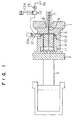
- reference numeral 1 designates a fixed plate of a clamping device in the injection molding apparatus
- reference numeral 2 designates a movable plate of the device.
- the fixed plate and the movable plate are respectively provided with a fixed mold half 3 and a movable mold half 4, which confront each other.
- the movable plate 2 is advanced and withdrawn by a clamping cylinder 5.
- the fixed mold half 3 and the movable mold half 4 provide a cavity 6 in a certain shape at engaged portions thereof.
- a synthetic resin molding material in a melted or softened state is injected and filled in the cavity, and the synthetic resin molding material cures or solidifies therein.
- the synthetic resin molding material is injected from an injection cylinder 7 with a screw therein into the cavity 6 through a nozzle 8 and a sprue 9.
- reference numeral 10 designates a rib (boss)
- reference numeral 11 designates an ejector pin for parting the mold halves.
- the fixed mold half 3 and the movable mold half 4 have the engaged portions provided with a share edge structure.
- the share edge structure is formed with an engagement groove (not shown), in which an elastic sealing member such as an O-ring is engaged to improve a sealing property of the share edge structure to a coating material.
- an injector 12 with a shut-off pin 12A, a coating material metering cylinder 13 for supplying a certain amount of coating material to the injector 12, and a supply pump 15 for supplying the coating material into the metering cylinder 13 from a storing unit 14 for the coating material.
- the metering cylinder 13 is provided with a plunger-regulator 13A for injecting the coating material.
- the clamping cylinder 5 is first activated to close the mold (the fixed mold half 3 and the movable mold half 4), and a clamping pressure is applied to the mold.
- the clamping pressure is required to counteract an injection pressure to the synthetic resin molding material.
- the injection pressure is normally as high as 400 - 2,500 kgf/cm 2 at the nozzle 8.
- the supply pump is activated to supply the required amount of coating material to the metering cylinder 13.
- the synthetic resin molding material in a melted or softened state is injected into the cavity 6 from the injection cylinder 7 through the nozzle 8.
- the clamping pressure is reduced, or the fixed mold half 3 and the movable mold half 4 are opened so that the engaged portions are not completely separated.
- the injector 12 activates the shut-off pin 12A to open an injection port thereof.
- the plunger-regulator 13A in the metering cylinder 13 is activated to inject the coating material into the cavity 6, or into between an inner wall of the fixed mold half 3 and a surface of the molded product.
- the clamping cylinder 5 is activated to clamp the mold, carrying out coating on the surface of the molded product in the mold.
- a mixing head 31 with a piston 30 having a shut-off function and an injection function, and metering cylinders 32 and 33 for supplying certain amounts of constituent agents for the coating material to the mixing head.
- the respective metering cylinders have hydraulic cylinders 36 and 37 provided therein to apply a pressure to each of the constituent agents.
- the constituent agents are jetted through confronting nozzles (not shown) in the mixing head 31 and are collided together to be mixed, providing the target coating material.
- methods for mixing the constituent agents there are a method using a static mixer, a method using a dynamic mixer and an atomizing method for instance. However, the method for mixing the constituent agents are not limited to these methods.
- a liquid main agent containing resin of a constituent agent for the coating material as a main component, and a liquid curing agent for curing the main agent are, respectively, subjected to temperature control in storing tanks 39 and 40 for the constituent agents, the liquid main agent and the liquid curing agent are pressurized at 50 - 200 bars by the hydraulic cylinders 36 and 37 in the metering cylinders 32 and 33, and the liquid main agent and the liquid curing agent are jetted through the confronting nozzles in the mixing head 31 to be mixed due to mutual impingement, providing the target coating material.
- the coating material is injected into between the inner wall of the fixed mold half 3 and the surface of the molded product by the piston 30 which works as a shut-off pin as well.
- the coating material When the coating material is prepared by mixing mutually reactive constituent agents immediately prior to injection as explained, the coating material has good fluidity on injection and is prevented from clogging since the coating material is free from thickening or gelation, which is different from use of a coating material prepared by preliminary mixing treatment.
- the clamping cylinder 5 is activated to clamp the mold, accomplishing coating on the surface of the molded product in the mold.
- the clamping speed and the clamping pressure of the clamping cylinder 5 after injection of the coating material are controlled by a proper controlling system to carry out the clamping process under different clamping pressures and different clamping speeds in a three-stage pattern as shown in Figure 3 for instance, curing the coating material.
- the clamping pressure in an initial stage is 10 - 100 kgf/cm 2 with respect to a projected area of the molded product. It is preferable that the clamping pressure transitional period of time in the initial stage is 0.5 - 10 sec, and that the clamping pressure maintaining period of time in the initial stage is 0.5 - 20 sec.
- the clamping pressure is lower than the range stated above, a uniform coating film is difficult to be formed on the entire surface of the molded product, and adhesion is apt to degrade. Conversely, when the clamping pressure is higher than the range, the humping prevention effect is apt to degrade.
- the clamping pressure in an intermediate stage is 20 - 80% of that in the initial stage, that the clamping pressure transitional period of time in the intermediate stage is 0.1 - 5 sec, and that the clamping pressure maintaining period of time in the intermediate stage is 0.5 - 20 sec.
- Clamping may be carried out under the same conditions as those on the intermediate stage in a final stage.
- the clamping pressure in the final stage is lower than that in the initial stage and 40 - 200% of that in the intermediate stage, that the clamping pressure transitional period of time in the final stage is 0.1 - 5 sec, and that the clamping pressure maintaining period of time in the final stage is not less than 1 sec.
- the clamping pressure maintaining period of time is 40 - 120 sec.
- the adhesion of the coating film is apt to degrade. Conversely, when the clamping pressure is higher than the range, cracks are apt to be formed on the coating film when a molded product is taken out of the mold.
- clamping pressure transitional period of time and the clamping pressure maintaining period of time have a tendency similar to that explained with respect to the intermediate stage.
- the critical factors in the embodiments are the presence of the multistagewise clamping pressures and the presence of the certain clamping pressure transitional periods of time after injection of the coating material, which are the conditions under which the rib or the boss on a molded product is prevented from rising (humping) to ensure high quality.
- the in-mold coating according to the present invention was applied to a mold which comprises a fixed mold half, a movable mold half and a cavity to form a molded product made of a synthetic resin molding material, the cavity having a box type of configuration of 200 mm in length, 150 mm in width and 10 mm in height, and a rib portion of 1 mm in width and 5 mm in depth.
- the fixed mold half 3 was set at a temperature of 120°C and the movable mold half 4 was set at a temperature of 115°C.
- polyamide resin was filled in the injection cylinder 7 and was heated to 220 - 240°C to be melted therein.
- a clamping pressure of 300 ton 1000 kgf/cm 2 with respect to a projected area of the molded product was applied to the mold.
- the resin was injected into the mold thus clamped for about 4 sec.
- the resin was cooled for 10 sec to be solidified to such an extent that a surface of the molded product could withstand an injection pressure and a flow pressure of a coating material.
- the coating material A that contains urethane acrylate oligomer and epoxy acrylate oligomer as main components (see Table 1) was measured to 3 cm 3 by the metering cylinder 13. Then, the coating material was injected into the cavity 6 in about 3 sec.
- the clamping pressure was increased to 21 ton (70 kgf/cm 2 with respect to the projected area of the molded product) in 2 sec, and the increased clamping pressure was maintained for 5 sec.
- the clamping pressure was reduced to 10 ton (33 kgf/cm 2 with respect to the projected area of the molded product) in 1 sec, and the reduced clamping pressure was maintained for 10 sec.
- the clamping pressure was reduced to 5 ton (17 kgf/cm 2 with respect to the projected area of the molded product) in 1 sec, and the reduced clamping pressure was maintained for 60 sec, curing the coating material.
- the rising amount of the rib portion on the molded product thus coated was checked by a sectional curve found by a surface texture measuring instrument (made by Tokyo Seimitsu Kabushiki Kaisha and commercially available under the trademark "SURFCOM").
- the rising amount of the rib portion on the molded product thus coated was 20.0 ⁇ m, which showed that the rib portion provided a poor surface in terms of uniformity.
- a mold included a cavity to form a molded product made of a synthetic resin molding material in a wheel cover form, the cavity having a configuration of 370 mm in diameter and a rib portion of 1.8 mm in width and 50 mm in depth.
- the fixed mold half 3 was set at a temperature of 120°C and the movable mold half 4 was set at a temperature of 115°C.
- modified polyphenylene ether resin was filled in the injection cylinder and was heated to 250 - 270°C to be melted therein.
- a clamping pressure of 500 ton 500 kgf/cm 2 with respect to a projected area of the molded product
- the resin was injected into the mold thus clamped for about 5 sec.
- the resin was cooled for about 20 sec to be solidified to such an extent that a surface of the molded product could withstand an injection pressure and a flow pressure of a coating material.
- the coating material B that contains urethane acrylate oligomer as a main component was measured to 10 cm 3 by the metering cylinder 13. Then, the coating material was injected into the cavity 6 in about 4 sec.
- the clamping pressure was increased to 40 ton (40 kgf/cm 2 with respect to the projected area of the molded product) in 5 sec, and the increased clamping pressure was maintained for 2 sec.
- the clamping pressure was reduced to 20 ton (20 kgf/cm 2 with respect to the projected area of the molded product) in 2 sec, and the reduced clamping pressure was maintained for 70 sec, curing the coating material.
- a mold included a cavity to form a molded product made of a synthetic resin molding material, the cavity having a box type of 200 mm in length, 150 mm in width and 10 mm in height.
- the fixed mold half 3 was set at a temperature of 155°C and the movable mold half 4 was set at a temperature of 160°C.
- a molding material called BMC containing unsaturated polyester resin as a matrix was injected into the mold to which a clamping pressure of 300 ton (1000 kgf/cm 2 with respect to a projected area of the molded product) was applied. The resin was cured for 60 sec.
- the coating material C that contains urethane acrylate oligomer and epoxy acrylate oligomer as main components (see Table 1) was measured to 3 cm 3 by the metering cylinder 13. Then, the coating material was injected into the cavity 6 in about 3 sec.
- the clamping pressure was increased to 21 ton (70 kgf/cm 2 with respect to the projected area of the molded product) in 1 sec, and the increased clamping pressure was maintained for 6 sec.
- the clamping pressure was reduced to 10 ton (33 kgf/cm 2 with respect to the projected area of the molded product) in 1 sec, and the reduced clamping pressure was maintained for 5 sec.
- the clamping pressure was increased to 15 ton (50 kgf/cm 2 with respect to the projected area of the molded product) in 1 sec, and the increased clamping pressure was maintained for 50 sec, curing the coating material.
- the in-mold coating according to the present invention was applied to a mold which comprises a fixed mold half, a movable mold half and a cavity to form a molded product made of a synthetic resin molding material in a wheel cover form, the cavity having a configuration of 370 mm in diameter, and a rib portion of 1.8 mm in width and 50 mm in depth.
- the fixed mold half 3 was set at a temperature of 120°C and the movable mold half 4 was set at a temperature of 115°C.
- modified polyphenylene ether resin was filled in the injection cylinder 7 and was heated to 250 - 270°C to be melted therein.
- a clamping pressure of 500 ton (500 kgf/cm 2 with respect to a projected area of the molded product) was applied to the mold.
- the resin was injected into the mold thus clamped for about 5 sec.
- the resin was cooled for 30 sec to be solidified to such an extent that a surface of the molded product could withstand an injection pressure and a flow pressure of a coating material.
- the coating material D that contains urethane acrylate oligomer as a main component was measured to 10 cm 3 by the metering cylinder 13. Then, the coating material was injected into the cavity 6 in about 2 sec.
- the clamping pressure was increased to 20 ton (20 kgf/cm 2 with respect to the projected area of the molded product) in 8 sec, and the increased clamping pressure was maintained for 2 sec.
- the clamping pressure was reduced to 10 ton (10 kgf/cm 2 with respect to the projected area of the molded product) in 2 sec, and the reduced clamping pressure was maintained for 5 sec.
- the clamping pressure was increased to 15 ton (15 kgf/cm 2 with respect to the projected area of the molded product) in 1 sec, and the increased clamping pressure was maintained for 80 sec, curing the coating material.
- Coating material (Parts by weight) Type of coating material A B C D Urethane acrylate oligomer (1) 10.0 - 16.0 - Urethane acrylate oligomer (2) - 55.0 - 54.0 Epoxy acrylate oligomer 20.0 - 16.0 - 1,6-Hexane diol diacrylate - 45.0 - 36.0 Styrene 24.0 - 22.0 - Titanium dioxide 45.0 - 45.0 - Aluminum pigment (average particle diameter: 30 ⁇ m) - 3.0 - - Aluminum pigment (average particle diameter: 22 ⁇ m) - - - 8.0 Zinc stearate 0.5 1.0 0.5 0.8 TINUVIN 292 - 1.0 - - TINUVIN 1130 - 0.5 - - 8% Cobalt octoate 0.5 0.5 0.1 0.2
- the in-mold coating according to the present invention was applied to a mold which includes a cavity to form a molded product made of a synthetic resin molding material in a box form, the cavity having a configuration of 300 mm in length, 300 mm in width and 30 mm in height, and a boss portion of 6 mm in diameter and 8 mm in depth.
- the mold temperature As the mold temperature, the fixed mold half 3 and the movable mold half were set at a temperature of 70°C.
- ABS resin was filled in the injection cylinder 7 and was heated to 220 - 240°C to be melted therein.
- a clamping pressure of 550 ton (610 kgf/cm 2 with respect to a projected area of the molded product) was applied to the mold.
- the resin was injected into the mold thus clamped for about 4 sec.
- the resin was cooled for 20 sec to be solidified to such an extent that a surface of the molded product could withstand an injection pressure and a flow pressure of a coating material.
- the clamping pressure was increased to 81 ton (90 kgf/cm 2 with respect to the projected area of the molded product) in 2 sec, and the increased clamping pressure was maintained for 5 sec.
- the clamping pressure was reduced to 20 ton (22 kgf/cm 2 with respect to the projected area of the molded product) in 2 sec, and the reduced clamping pressure was maintained for 10 sec.
- the clamping pressure was increased to 30 ton (33 kgf/cm 2 with respect to the projected area of the molded product) in 1 sec, and the increased clamping pressure was maintained for 60 sec, curing the coating material.
- the in-mold coating according to the present invention was applied to a mold which includes a cavity to form a molded product made of a synthetic resin molding material in a box form, the cavity having a configuration of 300 mm in length, 300 mm in width and 30 mm in height, and a boss portion of 6 mm in diameter and 8 mm in depth.
- the fixed mold half 3 was set at a temperature of 120°C and the movable mold half were set at a temperature of 115°C.
- polyamide resin was filled in the injection cylinder 7 and was heated to 220 - 240°C to be melted therein.
- a clamping pressure of 550 ton (610 kgf/cm 2 with respect to a projected area of the molded product) was applied to the mold.
- the resin was injected into the mold thus clamped for about 4 sec.
- the resin was cooled for 10 sec to be solidified to such an extent that a surface of the molded product could withstand an injection pressure and a flow pressure of a coating material.
- the clamping pressure was increased to 63 ton (70 kgf/cm 2 with respect to the projected area of the molded product) in 5 sec, and the increased clamping pressure was maintained for 5 sec.
- the clamping pressure was reduced to 30 ton (33 kgf/cm 2 with respect to the projected area of the molded product) in 1 sec, and the reduced clamping pressure was maintained for 20 sec.
- the clamping pressure was further reduced to 20 ton (22 kgf/cm 2 with respect to the projected area of the molded product) in 1 sec, and the increased clamping pressure was maintained for 60 sec, curing the coating material.
Landscapes
- Engineering & Computer Science (AREA)
- Mechanical Engineering (AREA)
- Manufacturing & Machinery (AREA)
- Injection Moulding Of Plastics Or The Like (AREA)
- Casting Or Compression Moulding Of Plastics Or The Like (AREA)
Applications Claiming Priority (4)
| Application Number | Priority Date | Filing Date | Title |
|---|---|---|---|
| JP1423998 | 1998-01-27 | ||
| JP1423998 | 1998-01-27 | ||
| JP24597798 | 1998-08-31 | ||
| JP24597798 | 1998-08-31 |
Publications (3)
| Publication Number | Publication Date |
|---|---|
| EP0934808A2 true EP0934808A2 (de) | 1999-08-11 |
| EP0934808A3 EP0934808A3 (de) | 1999-12-15 |
| EP0934808B1 EP0934808B1 (de) | 2002-09-04 |
Family
ID=26350150
Family Applications (1)
| Application Number | Title | Priority Date | Filing Date |
|---|---|---|---|
| EP99101406A Expired - Lifetime EP0934808B1 (de) | 1998-01-27 | 1999-01-26 | Verfahren zum Beschichten in einer Form |
Country Status (3)
| Country | Link |
|---|---|
| US (1) | US6180043B1 (de) |
| EP (1) | EP0934808B1 (de) |
| DE (1) | DE69902701T2 (de) |
Cited By (16)
| Publication number | Priority date | Publication date | Assignee | Title |
|---|---|---|---|---|
| EP1207031A1 (de) * | 1999-07-27 | 2002-05-22 | Dai Nippon Toryo Co., Ltd. | Verfahren zum beschichten der innenoberflächen eines metallwerkzeuges |
| WO2003035354A1 (en) * | 2001-10-22 | 2003-05-01 | Omnova Solutions, Inc. | Method for applying an in-mold coating on a surface area of an injection moulded substrate |
| WO2003043796A1 (fr) * | 2001-11-22 | 2003-05-30 | Dai Nippon Toryo Co., Ltd. | Procede de fabrication, dans un moule, d'un produit forme revetu |
| WO2004018177A1 (ja) * | 2002-08-23 | 2004-03-04 | Mitsui Chemicals, Inc. | 金型内被覆成形体およびその製造方法 |
| WO2004041518A1 (en) * | 2002-10-31 | 2004-05-21 | Omnova Solutions Inc. | Method and system for delivering and mixing multiple in-mold coating components |
| WO2004048067A1 (ja) * | 2002-11-25 | 2004-06-10 | Ube Machinery Corporation, Ltd. | 型内被覆成形方法及び型内被覆成形品 |
| US6793861B2 (en) | 2000-07-12 | 2004-09-21 | Omnova Solutions Inc. | Optimization of in-mold coating injection molded thermoplastic substrates |
| US6884056B2 (en) | 2002-04-03 | 2005-04-26 | Omnova Solutions Inc. | Mold runner for prevention of in-mold coating flow |
| US6887550B2 (en) | 2001-10-22 | 2005-05-03 | Omnova Solutions Inc. | Removable defined flange for in-mold coating containment |
| WO2006072366A1 (de) | 2004-12-24 | 2006-07-13 | Bayer Materialscience Ag | Verfahren und vorrichtung zum formen und beschichten eines substrats |
| US7289874B2 (en) | 2002-12-12 | 2007-10-30 | Omnova Solutions Inc. | Method of designing and producing a mold |
| US7547404B2 (en) | 2002-11-22 | 2009-06-16 | Omnova Solutions Inc. | Method for modifying existing mold systems to utilize an in-mold apparatus |
| DE102009005609B3 (de) * | 2009-01-21 | 2010-07-01 | Bayer Materialscience Ag | Werkzeug und Verfahren zur Herstellung von Mehrschicht-Kunststoffformteilen |
| WO2011076728A1 (de) * | 2009-12-23 | 2011-06-30 | Bayer Materialscience Ag | Polyurethan-bindemittel |
| CN111531795A (zh) * | 2020-05-18 | 2020-08-14 | 上海依呗科技有限公司 | 一种注塑模具填充饱满度感应辅助装置 |
| US10814803B2 (en) | 2015-06-03 | 2020-10-27 | Weidplas Gmbh | Component |
Families Citing this family (31)
| Publication number | Priority date | Publication date | Assignee | Title |
|---|---|---|---|---|
| US6500376B1 (en) * | 2000-01-27 | 2002-12-31 | Visteon Global Technologies, Inc. | Multiple injection compression molding process |
| AU2001250213A1 (en) * | 2000-04-20 | 2001-11-07 | Decoma Exterior Trim Inc. | Method of molding a panel |
| US6617033B1 (en) | 2000-07-12 | 2003-09-09 | Omnova Solutions Inc. | Method for in-mold coating a polyolefin article |
| US20040071980A1 (en) * | 2000-07-12 | 2004-04-15 | Mcbain Douglas S. | Method for in-mold coating a polyolefin article |
| US7105231B2 (en) * | 2001-10-22 | 2006-09-12 | Omnova Solutions Inc. | In-mold coating barrier for a substrate injection orifice |
| US7045213B2 (en) * | 2001-10-22 | 2006-05-16 | Omnova Solutions Inc. | In-mold coating injection inlet flow control |
| WO2004041503A1 (en) * | 2002-10-31 | 2004-05-21 | Omnova Solutions Inc. | Dispense and control apparatus and method for coating an injection molded article |
| US20040121034A1 (en) * | 2002-12-10 | 2004-06-24 | Mcbain Douglas S. | Integral injection molding and in-mold coating apparatus |
| NL1023365C2 (nl) * | 2003-05-08 | 2004-11-09 | Fountain Patents B V | Werkwijze en inrichting voor het vervaardigen van voertuigonderdelen. |
| DE102004028764A1 (de) * | 2004-06-16 | 2006-01-12 | Henkel Kgaa | Strahlungshärtbares elektrisch leitfähiges Beschichtungsgemisch |
| US20060118999A1 (en) * | 2004-12-06 | 2006-06-08 | Bayer Materialscience Llc | Method of preparing a coated molded article |
| US7314590B2 (en) * | 2005-09-20 | 2008-01-01 | Bayer Materialscience Llc | Method of preparing a coated molded plastic article |
| US20070138667A1 (en) * | 2005-12-21 | 2007-06-21 | Dang Hoa T | In-mold coating compositions for optical lenses |
| US7906047B2 (en) * | 2005-12-21 | 2011-03-15 | Essilor International (Compagnie Generale D'optique) | Injection molding a lens onto a coated ophthalmic wafer |
| US7833442B2 (en) * | 2005-12-21 | 2010-11-16 | Essilor International (Compagnie Generale D'optique) | Method for coating an ophthalmic lens within an injection molding machine |
| US20070138666A1 (en) * | 2005-12-21 | 2007-06-21 | Xu Chen | Method for coating an ophthalmic lens using stamp coating |
| US20090026639A1 (en) * | 2005-12-21 | 2009-01-29 | Xu Chen | Method of coating an ophthalmic lens using a stamp coating |
| DE102006009900B4 (de) * | 2006-03-03 | 2008-06-26 | Kraussmaffei Technologies Gmbh | Integrierte Systemvorrichtung zur Herstellung von Verbundkörpern |
| DE102006010310A1 (de) * | 2006-03-07 | 2007-09-13 | Krauss-Maffei Kunststofftechnik Gmbh | Vorrichtung und Verfahren zur Herstellung von Mehrkomponenten-Kunststoffteilen |
| JP2008043640A (ja) * | 2006-08-21 | 2008-02-28 | Aruze Corp | スロットマシン及びスロットマシンのプレイ方法 |
| WO2008134621A1 (en) * | 2007-04-27 | 2008-11-06 | Exatec, Llc | Abrasion resistant plastic glazing with in-mold coating |
| US20080272613A1 (en) | 2007-05-01 | 2008-11-06 | Weiss Keith D | Encapsulated plastic panel and method of making the same |
| WO2008141136A1 (en) * | 2007-05-09 | 2008-11-20 | Exatec. Llc | Pre-dry treatment of ink in decorative plastic glazing |
| US7759433B2 (en) | 2007-06-20 | 2010-07-20 | Essilor International (Compagnie Generale D'optique) | High adhesion acrylate coating for a photochromic ophthalmic lens |
| US7820082B2 (en) * | 2007-06-20 | 2010-10-26 | Essilor International (Compagne Generale D'optique) | Method for adding a thermoset overmold layer to a lens within a mold |
| US7820081B2 (en) * | 2008-05-14 | 2010-10-26 | Essilor International (Compagnie Generale D'optique) | Method for post-injection lamination to add a functional film to an optical lens |
| US9862842B2 (en) | 2012-02-29 | 2018-01-09 | Sabic Global Technologies B.V. | Infrared radiation absorbing articles and method of manufacture |
| EP2989237B1 (de) * | 2013-04-24 | 2021-03-17 | Automobile Patentverwaltungs- und Verwertungs- gesellschaft mbH | Verfahren zum beschichten von funktions-bauteilen aus kunststoff |
| WO2016028568A1 (en) * | 2014-08-22 | 2016-02-25 | Covestro Llc | Processes for in-mold coating using a multi-cavity mold and substrates coated thereby |
| US11104822B2 (en) | 2018-04-18 | 2021-08-31 | Covestro Llc | Processes for In-Mold coating systems for molding, and products formed therefrom |
| CN112873727B (zh) * | 2021-01-08 | 2022-09-06 | 宁波双盛塑料机械有限公司 | 一种改性塑料加工用注塑机 |
Family Cites Families (8)
| Publication number | Priority date | Publication date | Assignee | Title |
|---|---|---|---|---|
| US4082486A (en) * | 1976-12-02 | 1978-04-04 | General Motors Corporation | Apparatus for in-the-mold coating of molded articles |
| US4668460A (en) * | 1985-04-02 | 1987-05-26 | The Sherwin-Williams Company | Method of molding and coating a substrate in a mold. |
| DE3920774A1 (de) * | 1989-06-24 | 1991-01-10 | Ver Glaswerke Gmbh | Giessvorrichtung zum giessen transparenter kunststoffschichten mit einem eingefaerbten filterband |
| US5034077A (en) * | 1989-09-05 | 1991-07-23 | Jack Pata | Method for thermoforming and bonding a paint-coated polymeric film to a substrate |
| JPH03178412A (ja) * | 1989-12-07 | 1991-08-02 | Mazda Motor Corp | インモールドコート方法 |
| JPH05318527A (ja) * | 1992-05-21 | 1993-12-03 | Asahi Chem Ind Co Ltd | 成形体の製造方法 |
| US5902534A (en) * | 1994-09-21 | 1999-05-11 | Mitsubishi Engineering-Plastics Corp. | Method of injection-molding thermoplastic resins |
| JP3404546B2 (ja) | 1995-03-23 | 2003-05-12 | 大日本塗料株式会社 | 金型内被覆方法 |
-
1999
- 1999-01-25 US US09/235,766 patent/US6180043B1/en not_active Expired - Lifetime
- 1999-01-26 DE DE69902701T patent/DE69902701T2/de not_active Expired - Lifetime
- 1999-01-26 EP EP99101406A patent/EP0934808B1/de not_active Expired - Lifetime
Non-Patent Citations (1)
| Title |
|---|
| No relevant documents disclosed * |
Cited By (26)
| Publication number | Priority date | Publication date | Assignee | Title |
|---|---|---|---|---|
| EP1207031A4 (de) * | 1999-07-27 | 2003-04-09 | Dainippon Toryo Kk | Verfahren zum beschichten der innenoberflächen eines metallwerkzeuges |
| US7837918B2 (en) | 1999-07-27 | 2010-11-23 | Dai Nippon Toryo Co., Ltd. | Method of forming a coating layer on the surface of a molded product within a mold |
| US7832999B2 (en) | 1999-07-27 | 2010-11-16 | Dai Nippon Toryo Co., Ltd. | Method of forming a coating layer on the surface of a molded product within a mold |
| EP1207031A1 (de) * | 1999-07-27 | 2002-05-22 | Dai Nippon Toryo Co., Ltd. | Verfahren zum beschichten der innenoberflächen eines metallwerkzeuges |
| US6793861B2 (en) | 2000-07-12 | 2004-09-21 | Omnova Solutions Inc. | Optimization of in-mold coating injection molded thermoplastic substrates |
| US6887550B2 (en) | 2001-10-22 | 2005-05-03 | Omnova Solutions Inc. | Removable defined flange for in-mold coating containment |
| WO2003035354A1 (en) * | 2001-10-22 | 2003-05-01 | Omnova Solutions, Inc. | Method for applying an in-mold coating on a surface area of an injection moulded substrate |
| CN100336650C (zh) * | 2001-10-22 | 2007-09-12 | 阿姆诺洼化学有限公司 | 在注入成型基片表面区域施加模内涂层的方法 |
| US6890469B2 (en) | 2001-10-22 | 2005-05-10 | Omnova Solutions Inc. | Selectively controlling in-mold coating flow |
| US7790081B2 (en) | 2001-11-22 | 2010-09-07 | Dai Nippon Toryo Co., Ltd. | Method of manufacturing formed product coated in mold |
| WO2003043796A1 (fr) * | 2001-11-22 | 2003-05-30 | Dai Nippon Toryo Co., Ltd. | Procede de fabrication, dans un moule, d'un produit forme revetu |
| US6884056B2 (en) | 2002-04-03 | 2005-04-26 | Omnova Solutions Inc. | Mold runner for prevention of in-mold coating flow |
| US7482063B2 (en) | 2002-08-23 | 2009-01-27 | Prime Polymer Co., Ltd. | Molded object obtained by in-mold coating and process for producing the same |
| WO2004018177A1 (ja) * | 2002-08-23 | 2004-03-04 | Mitsui Chemicals, Inc. | 金型内被覆成形体およびその製造方法 |
| WO2004041518A1 (en) * | 2002-10-31 | 2004-05-21 | Omnova Solutions Inc. | Method and system for delivering and mixing multiple in-mold coating components |
| US7547404B2 (en) | 2002-11-22 | 2009-06-16 | Omnova Solutions Inc. | Method for modifying existing mold systems to utilize an in-mold apparatus |
| WO2004048067A1 (ja) * | 2002-11-25 | 2004-06-10 | Ube Machinery Corporation, Ltd. | 型内被覆成形方法及び型内被覆成形品 |
| US7862758B2 (en) | 2002-11-25 | 2011-01-04 | Ube Machinery Corporation, Ltd. | In-mold coat-forming method |
| US7289874B2 (en) | 2002-12-12 | 2007-10-30 | Omnova Solutions Inc. | Method of designing and producing a mold |
| WO2006072366A1 (de) | 2004-12-24 | 2006-07-13 | Bayer Materialscience Ag | Verfahren und vorrichtung zum formen und beschichten eines substrats |
| DE102009005609B3 (de) * | 2009-01-21 | 2010-07-01 | Bayer Materialscience Ag | Werkzeug und Verfahren zur Herstellung von Mehrschicht-Kunststoffformteilen |
| WO2010083959A1 (de) | 2009-01-21 | 2010-07-29 | Bayer Materialscience Ag | Werkzeug und verfahren zur herstellung von mehrschicht-kunststoffformteilen |
| WO2011076728A1 (de) * | 2009-12-23 | 2011-06-30 | Bayer Materialscience Ag | Polyurethan-bindemittel |
| US10814803B2 (en) | 2015-06-03 | 2020-10-27 | Weidplas Gmbh | Component |
| CN111531795A (zh) * | 2020-05-18 | 2020-08-14 | 上海依呗科技有限公司 | 一种注塑模具填充饱满度感应辅助装置 |
| CN111531795B (zh) * | 2020-05-18 | 2020-12-18 | 桐乡市佳盛塑料制品有限公司 | 一种注塑模具填充饱满度感应辅助装置 |
Also Published As
| Publication number | Publication date |
|---|---|
| EP0934808A3 (de) | 1999-12-15 |
| US6180043B1 (en) | 2001-01-30 |
| DE69902701D1 (de) | 2002-10-10 |
| DE69902701T2 (de) | 2003-08-07 |
| EP0934808B1 (de) | 2002-09-04 |
Similar Documents
| Publication | Publication Date | Title |
|---|---|---|
| EP0934808B1 (de) | Verfahren zum Beschichten in einer Form | |
| CA1110816A (en) | In mold coating of freshly molded articles | |
| US5902534A (en) | Method of injection-molding thermoplastic resins | |
| US5676901A (en) | Process for resin-coating of resin moldings, resin-coating apparatus for use in the process | |
| US4668460A (en) | Method of molding and coating a substrate in a mold. | |
| EP1434676B1 (de) | Verbesserung eines imc-beschichtungsverfahrens von spritzgegossenen thermoplastischen substraten | |
| CN101321616B (zh) | 一种在注模机中涂覆眼镜镜片的方法 | |
| EP1441888B1 (de) | Verfahren zum aufbringen einer imc-(in-mold-coating)-beschichtung auf einem oberflächenbereich eines spritzgegossenen substrates | |
| KR100704406B1 (ko) | 금형내 피복성형용 금형 및 그 금형을 사용한 금형내피복성형방법 | |
| US6676877B2 (en) | Mold runner for prevention of in-mold coating flow | |
| US7105231B2 (en) | In-mold coating barrier for a substrate injection orifice | |
| EP0197496B1 (de) | Formen und Beschichten in derselben Form | |
| US7045213B2 (en) | In-mold coating injection inlet flow control | |
| JP4420841B2 (ja) | 型内被覆用組成物及び型内被覆成形品の製造方法 | |
| EP0472312A2 (de) | Verfahren zum Filmbeschichten von Formteilen | |
| US7766648B2 (en) | Coating in multiple injection molding part cavities | |
| US20050156351A1 (en) | Apparatus and method for in-mold coating an article by injecting an in-mold coating through the article | |
| JP4456024B2 (ja) | 型内被覆成形用組成物及び型内被覆成形品の製造方法 | |
| JP4431514B2 (ja) | 型内被覆組成物及び型内被覆成形品の製造方法 | |
| JP2000141407A (ja) | 型内被覆方法 | |
| JP3406435B2 (ja) | 熱可塑性樹脂の射出成形方法 | |
| EP1501668B1 (de) | Selektive kontrolle eines in der form beschichtungsflusses mit eintrittsdurchflusssteuerung und mit einem abnehmbaren abdichtungsflansch | |
| JPH04105912A (ja) | 樹脂成形体への皮膜形成方法 | |
| JPH07112450A (ja) | 熱可塑性樹脂の射出成形方法 | |
| JPH11277577A (ja) | 型内被覆方法 |
Legal Events
| Date | Code | Title | Description |
|---|---|---|---|
| PUAI | Public reference made under article 153(3) epc to a published international application that has entered the european phase |
Free format text: ORIGINAL CODE: 0009012 |
|
| AK | Designated contracting states |
Kind code of ref document: A2 Designated state(s): DE FR GB IT |
|
| AX | Request for extension of the european patent |
Free format text: AL;LT;LV;MK;RO;SI |
|
| PUAL | Search report despatched |
Free format text: ORIGINAL CODE: 0009013 |
|
| AK | Designated contracting states |
Kind code of ref document: A3 Designated state(s): AT BE CH CY DE DK ES FI FR GB GR IE IT LI LU MC NL PT SE |
|
| AX | Request for extension of the european patent |
Free format text: AL;LT;LV;MK;RO;SI |
|
| RIC1 | Information provided on ipc code assigned before grant |
Free format text: 7B 29C 45/16 A |
|
| 17P | Request for examination filed |
Effective date: 20000118 |
|
| AKX | Designation fees paid |
Free format text: DE FR GB IT |
|
| 17Q | First examination report despatched |
Effective date: 20010119 |
|
| GRAG | Despatch of communication of intention to grant |
Free format text: ORIGINAL CODE: EPIDOS AGRA |
|
| GRAG | Despatch of communication of intention to grant |
Free format text: ORIGINAL CODE: EPIDOS AGRA |
|
| GRAH | Despatch of communication of intention to grant a patent |
Free format text: ORIGINAL CODE: EPIDOS IGRA |
|
| GRAH | Despatch of communication of intention to grant a patent |
Free format text: ORIGINAL CODE: EPIDOS IGRA |
|
| GRAA | (expected) grant |
Free format text: ORIGINAL CODE: 0009210 |
|
| AK | Designated contracting states |
Kind code of ref document: B1 Designated state(s): DE FR GB IT |
|
| REG | Reference to a national code |
Ref country code: GB Ref legal event code: FG4D |
|
| REF | Corresponds to: |
Ref document number: 69902701 Country of ref document: DE Date of ref document: 20021010 |
|
| ET | Fr: translation filed | ||
| PLBE | No opposition filed within time limit |
Free format text: ORIGINAL CODE: 0009261 |
|
| STAA | Information on the status of an ep patent application or granted ep patent |
Free format text: STATUS: NO OPPOSITION FILED WITHIN TIME LIMIT |
|
| 26N | No opposition filed |
Effective date: 20030605 |
|
| REG | Reference to a national code |
Ref country code: FR Ref legal event code: PLFP Year of fee payment: 17 |
|
| PGFP | Annual fee paid to national office [announced via postgrant information from national office to epo] |
Ref country code: DE Payment date: 20150121 Year of fee payment: 17 Ref country code: IT Payment date: 20150127 Year of fee payment: 17 |
|
| PGFP | Annual fee paid to national office [announced via postgrant information from national office to epo] |
Ref country code: FR Payment date: 20150122 Year of fee payment: 17 Ref country code: GB Payment date: 20150121 Year of fee payment: 17 |
|
| REG | Reference to a national code |
Ref country code: DE Ref legal event code: R119 Ref document number: 69902701 Country of ref document: DE |
|
| GBPC | Gb: european patent ceased through non-payment of renewal fee |
Effective date: 20160126 |
|
| REG | Reference to a national code |
Ref country code: FR Ref legal event code: ST Effective date: 20160930 |
|
| PG25 | Lapsed in a contracting state [announced via postgrant information from national office to epo] |
Ref country code: DE Free format text: LAPSE BECAUSE OF NON-PAYMENT OF DUE FEES Effective date: 20160802 Ref country code: GB Free format text: LAPSE BECAUSE OF NON-PAYMENT OF DUE FEES Effective date: 20160126 |
|
| PG25 | Lapsed in a contracting state [announced via postgrant information from national office to epo] |
Ref country code: FR Free format text: LAPSE BECAUSE OF NON-PAYMENT OF DUE FEES Effective date: 20160201 |
|
| PG25 | Lapsed in a contracting state [announced via postgrant information from national office to epo] |
Ref country code: IT Free format text: LAPSE BECAUSE OF NON-PAYMENT OF DUE FEES Effective date: 20160126 |