EP0934458B1 - Lastverstelleinrichtung - Google Patents
Lastverstelleinrichtung Download PDFInfo
- Publication number
- EP0934458B1 EP0934458B1 EP97912153A EP97912153A EP0934458B1 EP 0934458 B1 EP0934458 B1 EP 0934458B1 EP 97912153 A EP97912153 A EP 97912153A EP 97912153 A EP97912153 A EP 97912153A EP 0934458 B1 EP0934458 B1 EP 0934458B1
- Authority
- EP
- European Patent Office
- Prior art keywords
- supporting plate
- adjusting device
- throttle valve
- load adjusting
- plug
- Prior art date
- Legal status (The legal status is an assumption and is not a legal conclusion. Google has not performed a legal analysis and makes no representation as to the accuracy of the status listed.)
- Expired - Lifetime
Links
- 230000001629 suppression Effects 0.000 claims description 7
- 239000004020 conductor Substances 0.000 claims description 5
- 238000002485 combustion reaction Methods 0.000 claims description 3
- OKTJSMMVPCPJKN-UHFFFAOYSA-N Carbon Chemical compound [C] OKTJSMMVPCPJKN-UHFFFAOYSA-N 0.000 claims 3
- 229910052799 carbon Inorganic materials 0.000 claims 3
- 238000004519 manufacturing process Methods 0.000 description 3
- 239000000853 adhesive Substances 0.000 description 1
- 238000004026 adhesive bonding Methods 0.000 description 1
- 230000001070 adhesive effect Effects 0.000 description 1
- 230000015572 biosynthetic process Effects 0.000 description 1
- 239000003990 capacitor Substances 0.000 description 1
- 239000003245 coal Substances 0.000 description 1
- 230000000295 complement effect Effects 0.000 description 1
- 238000010276 construction Methods 0.000 description 1
- 230000001419 dependent effect Effects 0.000 description 1
- 239000000428 dust Substances 0.000 description 1
- 230000000694 effects Effects 0.000 description 1
- 230000007613 environmental effect Effects 0.000 description 1
- 238000005755 formation reaction Methods 0.000 description 1
- 238000003780 insertion Methods 0.000 description 1
- 230000037431 insertion Effects 0.000 description 1
- 230000001681 protective effect Effects 0.000 description 1
- 238000007789 sealing Methods 0.000 description 1
- 238000005476 soldering Methods 0.000 description 1
- 230000007704 transition Effects 0.000 description 1
Images


Classifications
-
- F—MECHANICAL ENGINEERING; LIGHTING; HEATING; WEAPONS; BLASTING
- F02—COMBUSTION ENGINES; HOT-GAS OR COMBUSTION-PRODUCT ENGINE PLANTS
- F02D—CONTROLLING COMBUSTION ENGINES
- F02D11/00—Arrangements for, or adaptations to, non-automatic engine control initiation means, e.g. operator initiated
- F02D11/06—Arrangements for, or adaptations to, non-automatic engine control initiation means, e.g. operator initiated characterised by non-mechanical control linkages, e.g. fluid control linkages or by control linkages with power drive or assistance
- F02D11/10—Arrangements for, or adaptations to, non-automatic engine control initiation means, e.g. operator initiated characterised by non-mechanical control linkages, e.g. fluid control linkages or by control linkages with power drive or assistance of the electric type
Definitions
- the invention relates to a load adjustment device with a in a throttle valve housing arranged throttle valve for power control an internal combustion engine according to the preamble of the claim 1.
- a load adjustment device in which a throttle valve is rotatably mounted in a throttle valve housing.
- the throttle valve is dependent on predeterminable parameters of an actuating device, in particular an electric motor, for power control the internal combustion engine set.
- an actuating device in particular an electric motor, for power control the internal combustion engine set.
- an electric motor for power control the internal combustion engine set.
- the throttle body is a throttle potentiometer with its own Wiring and also the electric motor with its own wiring, individually must be led out of the throttle body, arranged.
- This arrangement has the disadvantage that a large number of components the assembly effort is considerable and due to the use of wiring there is a risk of a cable break.
- the invention is therefore based on the object of a load adjustment device of the type mentioned in such a way that while maintaining the compact design of the assembly effort is simplified and the risk of line breaks is avoided.
- the use of a carrier plate with electrically conductive areas has the Advantage that the wiring can be omitted, especially if the electrically conductive areas with the electrical connection (plug) are connected.
- Another advantage is that when assembling the Load adjustment device, the carrier plate only in the throttle body must be used so that additional handles such as embarrassed the cables or soldering or the like are omitted. This is particularly so particularly important in the series production of load adjustment devices Advantage, because this gives a considerable time advantage in production is.
- This has the advantage that there are already elements of the electric motor can be pre-assembled in the carrier plate, so that the wiring of the electric motor is also eliminated. Beyond that it is advantageous that different in a preconfigured carrier plate Electric motors can be used.
- the carrier plate takes interference suppressors such as for example interference suppression chokes, interference suppression capacitors or the like, for the actuator.
- interference suppressors such as for example interference suppression chokes, interference suppression capacitors or the like.
- the carrier plate has an electrical connection a plug or a socket, the plug and / or the socket designed in one part or in several parts, in particular in two parts is.
- the plug or socket with the carrier plate can be a Form unit, which is particularly important in the manufacture of the carrier plate Advantage is, or be designed as a separate component, which is then the advantage has different types of plugs or sockets that are different Formations can have, for example, depending on the particular Manufacturer, and on the carrier plate, for example by screwing, Gluing or the like can be attached.
- part of the multi-part Plug or the multi-part socket can be connected to the carrier plate is.
- connection in particular between one connected to a coal of the electric motor electrical connection and the throttle body Leakage resistance switched.
- the leakage resistance is arranged on or in the carrier plate and can, for example connected to the throttle body by a clamp connection become.
- the electrically conductive areas of the Carrier plate designed as conductor tracks arranged on the carrier plate.
- the conductor tracks cannot be etched away required entire, electrically conductive areas on the carrier plate getting produced.
- the carrier plate is constructed in multiple layers, being between an electrically non-conductive top and bottom layer the electrically conductive areas are inserted. This is particularly so then advantageous if, for example, the electric motor is high Currents flow for which the conductor tracks would not have been designed.
- the carrier plate is constructed in several parts and in the connection area, especially the end faces, of several Carrier plate parts an electrical transition of the respective electrically conductive Areas provided.
- several carrier plate parts are put together, which vary according to geometric dimensions or other specifications can distinguish.
- a base plate is used, the one the electrical Connection and the springs of the electric motor picks up and on the other an additional support plate can be connected to it, which supports the several path areas of the throttle valve potentiometer.
- the multiple carrier plate parts can, for example, accommodate bores, into the throttle body pins after assembly intervene and fix the carrier plate parts in position.
- the carrier plate or several Carrier plate parts of the throttle body and one of the throttle body closing lid or other covering fixable.
- the invention allows a variety of configurations, in particular with regard to the geometric configuration of the carrier plate, to a preferred embodiment without the invention to this Embodiment is limited, described below and with reference of the figures explained.
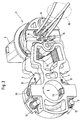
- FIGS. 1 to 3 show different views of a carrier plate 1 shown in a throttle body of a throttle body can be used, the same components having the same reference numbers have been provided.
- the carrier plate 1 designed as a flat plate, but can also be complex geometric Contours as shown, for example, in FIGS. 1 to 3, exhibit.
- Figure 1 it is shown that the carrier plate 1 from a first Layer 2 and a second layer 3, between them two layers 2 and 3 isolate several insert sheets 4 from one another, which represent the electrically conductive area are inserted.
- the two Layers 2 can be taken by appropriate measures such as Adhesive bonded together, but it is also conceivable that the carrier plate 1 in one piece with the insert of the electrically conductive areas is poured.
- a connector 5 Attached to the support plate 1 or cast on it is a connector 5, which is a basic version, around other plug or socket parts such as Sleeves are added can. Furthermore, fixing areas 6 and 7 are on the carrier plate 1 in the form of webs (cast on) with which the carrier plate 1 fixed in position and possibly at a distance in the throttle body is arranged. In an end region which is preferably elongated trained carrier plate 1, there is an opening 8 through which at least the collector of the electric motor, not shown in Figures 1 to 3 is feasible or feasible. For mounting and fastening the coals of the electric motor are provided with pins and insertion openings 10, which will be described later.
- Figure 2 also shows a mounting hole 11 with which the Carrier plate 1 is fixed in position, for example, by means of at least one screw and is vibration-proof connected to the throttle body.
- FIG. 3 shows that on further contacts of the plug 5 with a wire harness 16 several cables is arranged, in this embodiment to one Throttle valve potentiometer, not shown.
- the cable of the wiring harness 16 as rigid, electrically conductive areas in or on the carrier plate 1 are arranged and the carrier plate 1 also the throttle potentiometer in unit or external part.
- the coals 13 via a connecting cord 17 with the electrically conductive area (insert plate 4) is connected.
- FIG. 4 shows an electrical connection in the form of a plug 5, wherein the electrical connection is of course also designed as a socket can be.
- the reference numeral 18 is the part shown Shown the throttle body, in which the carrier plate 1 is used.
- the connector 5 shown has a first part 19 on, which is either arranged on the carrier plate 1 or with the carrier plate 1 forms a structural unit (for example is cast on).
- the second part 20 of the plug 5 is interposed with a rotating one Seal 21 advantageously over the first part 19, wherein the second part 20 of the plug 5 advantageously meets the requirements of the vehicle manufacturer in which the load adjustment device is installed, is adjusted. From the first part 19, a plurality of contact pins 22 are sealing led out, the protective part of the second part 20 are.
- a socket contact 23 is provided which either with the insert plate 4 is connected (when viewing FIG. 4 the right contact pin 22), is connected to a cable of the cable harness 16 (when considering 4, the middle contact pin 22) or with a conductor track 24, the is located on the top of the carrier plate 1, is soldered (when viewed 4 the left contact pin 22).
- the carrier plate 1 is only one of the mentioned contacts or a combination of these is possible.
Landscapes
- Engineering & Computer Science (AREA)
- Chemical & Material Sciences (AREA)
- Combustion & Propulsion (AREA)
- Mechanical Engineering (AREA)
- General Engineering & Computer Science (AREA)
- Control Of Throttle Valves Provided In The Intake System Or In The Exhaust System (AREA)
Description
- Figuren 1 bis 3:
- verschiedene Seitenansichten einer Trägerplatte,
- Figur 4:
- den Aufbau eines mehrteiligen Steckers.
Claims (12)
- Lastverstelleinrichtung mit einer in einem einen elektrischen Anschluß aufweisenden Drosselklappengehäuse (18) angeordneten Drosselklappe, die die Leistung einer Brennkraftmaschine einstellend von einer Stelleinrichtung, insbesondere ein Elektromotor, antreibbar ist, dadurch gekennzeichnet, daß in dem Drosselklappengehäuse (18) eine Trägerplatte (1) mit elektrisch leitenden Bereichen eingelegt ist, wobei der elektrische Anschluß zumindest mit der Stelleinrichtung über die elektrisch leitenden Bereiche der Trägerplatte (1) verbunden ist.
- Lastverstelleinrichtung nach Anspruch 1, dadurch gekennzeichnet, daß die als Elektromotor ausgebildete Stelleinrichtung in an sich bekannter Weise mittels Federn (12) belastete, mit einem Kollektor des Elektromotors in Verbindung stehende Kohlen (13) aufweist, wobei zumindest die Kohlen (13) und die Federn (12) an und/oder in der Trägerplatte (1) angeordnet sind.
- Lastverstelleinrichtung nach Anspruch 1 oder 2, dadurch gekennzeichnet, daß die Trägerplatte (1) Entstörmittel (Entstördrosseln 14) für die Steileinrichtung aufnimmt.
- Lastverstelleinrichtung nach einem der Ansprüche 1 bis 3, dadurch gekennzeichnet, daß die Trägerplatte (1) als elektrischen Anschluß einen Stecker (5) oder eine Buchse aufweist, wobei der Stecker (5) oder die Buchse einteilig oder mehrteilig, insbesondere zweiteilig, ausgestaltet ist.
- Lastverstelleinrichtung nach Anspruch 4, dadurch gekennzeichnet, daß ein Teil (19) des zweiteiligen Steckers (5) oder der zweiteiligen Buchse mit der Trägerplatte (1) verbindbar ist oder mit der Trägerplatte (1) eine Baueinheit bildet sowie ein weiterer Teil (20) des zweiteiligen Steckers (5) oder der zweiteiligen Buchse mit dem ersten Teil (19) verbindbar ist.
- Lastverstelleinrichtung nach Anspruch 4 oder 5, dadurch gekennzeichnet, daß zwischen dem Stecker (5) oder der Buchse bzw. zwischen den beiden Teilen (19, 20) des Steckers (5) oder der Buchse und dem Drosselklappengehäuse (18) eine Dichtung (21) vorgesehen ist.
- Lastverstelleinrichtung nach einem der vorhergehenden Ansprüche, dadurch gekennzeichnet, daß auf der Trägerplatte (1) mehrere Bahnbereiche eines Drosselklappen-Potentiometers zur Erfassung der Stellung der Drosselklappe angeordnet sind, wobei sich die Trägerplatte (1) um einen Bereich einer Drosselklappenwelle herum erstreckt und die mehreren Bahnbereiche konzentrisch um die Drosselklappenwelle angeordnet sind.
- Lastverstelleinrichtung nach einem der vorhergehenden Ansprüche, dadurch gekennzeichnet, daß zwischen einem Anschluß, insbesondere zwischen einer mit einer Kohle (13), des Elektromotors in Verbindung stehenden elektrischen Verbindung und dem Drosselklappengehäuse (18) ein Ableitwiderstand geschaltet ist.
- Lastverstelleinrichtung nach einem der vorhergehenden Ansprüche, dadurch gekennzeichnet, daß die elektrisch leitenden Bereiche der Trägerplatte (1) als auf der Trägerplatte (1) angeordnete Leiterbahnen (24) ausgebildet sind.
- Lastverstelleinrichtung nach einem der vorhergehenden Ansprüche, dadurch gekennzeichnet, daß die Trägerplatte (1) mehrschichtig ausgebildet ist, wobei zwischen einer elektrisch nicht leitenden Ober- und Unterschicht (2, 3) die elektrisch leitenden Bereiche eingelegt sind (Einlegebleche 4)
- Lastverstelleinrichtung nach einem der vorhergehenden Ansprüche, dadurch gekennzeichnet, daß die Trägerplatte (1) mehrteilig ausgebildet ist und im Verbindungsbereich der mehreren Trägerplattenteile ein elektrischer Übergang der jeweiligen elektrisch leitenden Bereiche vorgesehen ist.
- Lastverstelleinrichtung nach einem der vorhergehenden Ansprüche, dadurch gekennzeichnet, daß die Trägerplatte (1) oder die mehreren Trägerplattenteile von dem Drosselklappengehäuse (18) und einer das Drosselklappengehäuse (18) verschließenden Abdeckung (Deckel) fixierbar ist oder sind.
Applications Claiming Priority (3)
| Application Number | Priority Date | Filing Date | Title |
|---|---|---|---|
| DE19644169A DE19644169A1 (de) | 1996-10-24 | 1996-10-24 | Lastverstelleinrichtung |
| DE19644169 | 1996-10-24 | ||
| PCT/EP1997/005560 WO1998017905A1 (de) | 1996-10-24 | 1997-10-09 | Lastverstelleinrichtung |
Publications (2)
| Publication Number | Publication Date |
|---|---|
| EP0934458A1 EP0934458A1 (de) | 1999-08-11 |
| EP0934458B1 true EP0934458B1 (de) | 2002-03-27 |
Family
ID=7809838
Family Applications (1)
| Application Number | Title | Priority Date | Filing Date |
|---|---|---|---|
| EP97912153A Expired - Lifetime EP0934458B1 (de) | 1996-10-24 | 1997-10-09 | Lastverstelleinrichtung |
Country Status (6)
| Country | Link |
|---|---|
| US (1) | US6259184B1 (de) |
| EP (1) | EP0934458B1 (de) |
| KR (1) | KR100491153B1 (de) |
| BR (1) | BR9712437A (de) |
| DE (2) | DE19644169A1 (de) |
| WO (1) | WO1998017905A1 (de) |
Families Citing this family (10)
| Publication number | Priority date | Publication date | Assignee | Title |
|---|---|---|---|---|
| US6456293B1 (en) * | 1998-12-11 | 2002-09-24 | James C. Grandy | Method and apparatus for working with constrained color on a computer terminal display |
| DE10112427A1 (de) * | 2001-03-15 | 2002-09-19 | Bosch Gmbh Robert | Elektromotorische Stelleinheit für ein Zumeßsystem einer Brennkraftmaschine |
| KR100484624B1 (ko) * | 2002-12-12 | 2005-04-22 | 주식회사 캄코 | 직부식 커넥터가 장착된 콘덴서용 쿨링팬 모터 |
| DE10341394A1 (de) * | 2003-09-05 | 2005-04-28 | Pierburg Gmbh | Stellvorrichtung |
| DE10353432B4 (de) | 2003-11-15 | 2009-07-09 | Pierburg Gmbh | Kontakteinheit |
| DE102004059171A1 (de) * | 2004-12-08 | 2006-06-14 | Siemens Ag | Teileinheit zur Betätigung einer drehbar gelagerten Welle, deren aktueller Drehwinkel kontinuierlich zu erfassen ist |
| ITTO20111086A1 (it) * | 2011-11-25 | 2013-05-26 | Gate Srl | Motore elettrico in corrente continua con spazzole, provvisto di un filtro contro l'emissione di disturbi elettromagnetici |
| US10491080B2 (en) | 2013-12-20 | 2019-11-26 | Johnson Electric International AG | Brush assembly |
| CN104734449B (zh) * | 2013-12-20 | 2018-12-04 | 德昌电机(深圳)有限公司 | 电刷装置及使用该电刷装置的有刷电机 |
| CN114157099B (zh) * | 2021-12-14 | 2023-05-05 | 深圳市唯真电机发展有限公司 | 一种集成电机 |
Family Cites Families (16)
| Publication number | Priority date | Publication date | Assignee | Title |
|---|---|---|---|---|
| DE3021948A1 (de) * | 1980-06-12 | 1981-12-24 | Rau Swf Autozubehoer | Elektrische antriebseinheit, insbesondere fuer scheibenwischer eines kraftfahrzeuges |
| DE3405935A1 (de) * | 1984-02-18 | 1985-08-22 | Vdo Adolf Schindling Ag, 6000 Frankfurt | Drosselklappenstelleinrichtung |
| JPS60190626A (ja) * | 1984-03-09 | 1985-09-28 | Hitachi Ltd | 絞弁制御装置 |
| JPS61279742A (ja) * | 1985-06-05 | 1986-12-10 | Nippon Denso Co Ltd | 車両用スロツトル弁開度検出装置 |
| DE8527874U1 (de) * | 1985-09-30 | 1986-08-07 | Siemens AG, 1000 Berlin und 8000 München | Kommutatormotor in geschlossener Bauart |
| US4926075A (en) * | 1987-12-28 | 1990-05-15 | Makita Electric Works, Ltd. | Electric motor brush assembly adaptable to different stators |
| DE3815735A1 (de) * | 1988-05-07 | 1989-11-16 | Vdo Schindling | Lastverstelleinrichtung |
| JPH0649100Y2 (ja) * | 1989-12-04 | 1994-12-12 | 株式会社三ツ葉電機製作所 | 直流機の配線装置 |
| DE4100381A1 (de) * | 1991-01-09 | 1992-07-16 | Vdo Schindling | Lastverstelleinrichtung fuer eine drosselklappengeregelte brennkraftmaschine |
| IT1259443B (it) | 1992-10-29 | 1996-03-18 | Weber Srl | Dispositivo di alimentazione aria per un motore a combustione interna. |
| EP0618659B2 (de) * | 1993-03-31 | 2001-07-04 | Siemens Aktiengesellschaft | Kommutatormotor-Getriebe-Antriebseinheit, insbesondere Kraftfahrzeug-Fensterheberantrieb |
| US5460035A (en) * | 1993-06-23 | 1995-10-24 | Cts Corporation | Bearing free spring free throttle position sensor |
| US5440186A (en) * | 1993-09-13 | 1995-08-08 | United Technologies Automotive, Inc. | Motor with isolated brush card assembly |
| DE4443502A1 (de) * | 1994-12-07 | 1996-06-13 | Bosch Gmbh Robert | Vorrichtung für eine Brennkraftmaschine |
| EP1050674B1 (de) * | 1995-01-17 | 2003-04-16 | Hitachi, Ltd. | Lüftströmungssteuervorrichtung |
| DE19540323B4 (de) * | 1995-10-28 | 2008-06-05 | Robert Bosch Gmbh | Drosselklappenstutzen |
-
1996
- 1996-10-24 DE DE19644169A patent/DE19644169A1/de not_active Ceased
-
1997
- 1997-10-09 WO PCT/EP1997/005560 patent/WO1998017905A1/de not_active Ceased
- 1997-10-09 EP EP97912153A patent/EP0934458B1/de not_active Expired - Lifetime
- 1997-10-09 BR BR9712437-0A patent/BR9712437A/pt not_active IP Right Cessation
- 1997-10-09 KR KR10-1999-7003324A patent/KR100491153B1/ko not_active Expired - Fee Related
- 1997-10-09 US US09/284,777 patent/US6259184B1/en not_active Expired - Lifetime
- 1997-10-09 DE DE59706795T patent/DE59706795D1/de not_active Expired - Lifetime
Also Published As
| Publication number | Publication date |
|---|---|
| DE59706795D1 (de) | 2002-05-02 |
| KR100491153B1 (ko) | 2005-05-24 |
| EP0934458A1 (de) | 1999-08-11 |
| US6259184B1 (en) | 2001-07-10 |
| WO1998017905A1 (de) | 1998-04-30 |
| DE19644169A1 (de) | 1998-04-30 |
| BR9712437A (pt) | 1999-10-19 |
| KR20000049223A (ko) | 2000-07-25 |
Similar Documents
| Publication | Publication Date | Title |
|---|---|---|
| DE19964156B4 (de) | Elektrisches Gerät | |
| EP3050175A1 (de) | Steckverbinderteil mit einer widerstandkodierung | |
| EP2790272B1 (de) | Anordnung zur Stromverteilung sowie deren Kontaktierung und Absicherung der abgehenden Leitungen | |
| DE202014102609U1 (de) | Hochvolt-Verteilerbox insbesondere für ein Kraftfahrzeug | |
| DE3435566C2 (de) | ||
| DE19644169A1 (de) | Lastverstelleinrichtung | |
| DE4319720C2 (de) | Zündvorrichtung für einen Verbrennungsmotor | |
| DE10010439C2 (de) | Stellantrieb bzw. Verfahren zur Montage eines Stellantriebs | |
| DE20307863U1 (de) | Ausgangsspannungsverteiler mit Sicherung | |
| DE29701828U1 (de) | Modul zum Anschluß eines Aktuators oder Sensors | |
| DE102022109354B4 (de) | Dichtung für doppelschienen-leiteranordnung | |
| DE102020210692A1 (de) | Elektrische Maschine mit einer elektrisch leitenden Abschirmplatte | |
| DE4132310C2 (de) | Zündverteiler für einen Verbrennungsmotor | |
| DE20307865U1 (de) | Ausgangsspannungsverteiler | |
| EP0834966B1 (de) | Steckverbindung für eine unterhalb einer Abdeckung befindliche Baugruppe | |
| DE202020005555U1 (de) | Elektrische Maschine mit einer elektrisch leitenden Abschirmplatte | |
| DE202018102741U1 (de) | Lichtband | |
| DE10255096B4 (de) | Zündvorrichtung für eine innere Verbrennungskraftmaschine | |
| DE10032306B4 (de) | Mit Motor vereinigte Steuerung und in dieser verwendete Schaltungsplatinengehäuse | |
| DE3908532C2 (de) | ||
| DE4343203C1 (de) | Mittelspannungs- oder Hochspannungsarmatur | |
| DE19845776A1 (de) | T-förmige Verbindungsanschlüsse für gasisolierte Mittelspannungsschaltanlagen | |
| EP0568795B1 (de) | Niedervolt-Elektrifiziereinrichtung für Kastenmöbel oder Innenausbauten | |
| DE4238776C2 (de) | Anordnung zur Erdung der Schirmleiter geschirmter Kabel | |
| DE3831859A1 (de) | Luftfeder mit einer vorrichtung zur leitungsverbindung |
Legal Events
| Date | Code | Title | Description |
|---|---|---|---|
| PUAI | Public reference made under article 153(3) epc to a published international application that has entered the european phase |
Free format text: ORIGINAL CODE: 0009012 |
|
| AK | Designated contracting states |
Kind code of ref document: A1 Designated state(s): DE FR GB |
|
| 17P | Request for examination filed |
Effective date: 19990331 |
|
| GRAG | Despatch of communication of intention to grant |
Free format text: ORIGINAL CODE: EPIDOS AGRA |
|
| GRAG | Despatch of communication of intention to grant |
Free format text: ORIGINAL CODE: EPIDOS AGRA |
|
| GRAH | Despatch of communication of intention to grant a patent |
Free format text: ORIGINAL CODE: EPIDOS IGRA |
|
| 17Q | First examination report despatched |
Effective date: 20010704 |
|
| REG | Reference to a national code |
Ref country code: GB Ref legal event code: IF02 |
|
| RAP1 | Party data changed (applicant data changed or rights of an application transferred) |
Owner name: SIEMENS AKTIENGESELLSCHAFT |
|
| GRAH | Despatch of communication of intention to grant a patent |
Free format text: ORIGINAL CODE: EPIDOS IGRA |
|
| GRAA | (expected) grant |
Free format text: ORIGINAL CODE: 0009210 |
|
| AK | Designated contracting states |
Kind code of ref document: B1 Designated state(s): DE FR GB |
|
| REF | Corresponds to: |
Ref document number: 59706795 Country of ref document: DE Date of ref document: 20020502 |
|
| ET | Fr: translation filed | ||
| PLBE | No opposition filed within time limit |
Free format text: ORIGINAL CODE: 0009261 |
|
| STAA | Information on the status of an ep patent application or granted ep patent |
Free format text: STATUS: NO OPPOSITION FILED WITHIN TIME LIMIT |
|
| 26N | No opposition filed |
Effective date: 20021230 |
|
| PGFP | Annual fee paid to national office [announced via postgrant information from national office to epo] |
Ref country code: FR Payment date: 20081014 Year of fee payment: 12 |
|
| PGFP | Annual fee paid to national office [announced via postgrant information from national office to epo] |
Ref country code: GB Payment date: 20081021 Year of fee payment: 12 |
|
| REG | Reference to a national code |
Ref country code: FR Ref legal event code: ST Effective date: 20100630 |
|
| PG25 | Lapsed in a contracting state [announced via postgrant information from national office to epo] |
Ref country code: FR Free format text: LAPSE BECAUSE OF NON-PAYMENT OF DUE FEES Effective date: 20091102 |
|
| PG25 | Lapsed in a contracting state [announced via postgrant information from national office to epo] |
Ref country code: GB Free format text: LAPSE BECAUSE OF NON-PAYMENT OF DUE FEES Effective date: 20091009 |
|
| PGFP | Annual fee paid to national office [announced via postgrant information from national office to epo] |
Ref country code: DE Payment date: 20141031 Year of fee payment: 18 |
|
| REG | Reference to a national code |
Ref country code: DE Ref legal event code: R119 Ref document number: 59706795 Country of ref document: DE |
|
| PG25 | Lapsed in a contracting state [announced via postgrant information from national office to epo] |
Ref country code: DE Free format text: LAPSE BECAUSE OF NON-PAYMENT OF DUE FEES Effective date: 20160503 |