EP0933932A1 - Zwischenfrequenz-Ausgangsschaltung - Google Patents
Zwischenfrequenz-Ausgangsschaltung Download PDFInfo
- Publication number
- EP0933932A1 EP0933932A1 EP99300389A EP99300389A EP0933932A1 EP 0933932 A1 EP0933932 A1 EP 0933932A1 EP 99300389 A EP99300389 A EP 99300389A EP 99300389 A EP99300389 A EP 99300389A EP 0933932 A1 EP0933932 A1 EP 0933932A1
- Authority
- EP
- European Patent Office
- Prior art keywords
- frequency
- circuit
- trap
- electrically connected
- tuning circuit
- Prior art date
- Legal status (The legal status is an assumption and is not a legal conclusion. Google has not performed a legal analysis and makes no representation as to the accuracy of the status listed.)
- Granted
Links
- 239000003990 capacitor Substances 0.000 abstract description 45
- 230000005540 biological transmission Effects 0.000 description 7
- 238000010586 diagram Methods 0.000 description 6
- 230000002238 attenuated effect Effects 0.000 description 3
- 230000008054 signal transmission Effects 0.000 description 3
- 230000004048 modification Effects 0.000 description 2
- 238000012986 modification Methods 0.000 description 2
Images

Classifications
-
- H—ELECTRICITY
- H04—ELECTRIC COMMUNICATION TECHNIQUE
- H04N—PICTORIAL COMMUNICATION, e.g. TELEVISION
- H04N5/00—Details of television systems
- H04N5/44—Receiver circuitry for the reception of television signals according to analogue transmission standards
- H04N5/4446—IF amplifier circuits specially adapted for B&W TV
-
- H—ELECTRICITY
- H03—ELECTRONIC CIRCUITRY
- H03H—IMPEDANCE NETWORKS, e.g. RESONANT CIRCUITS; RESONATORS
- H03H7/00—Multiple-port networks comprising only passive electrical elements as network components
- H03H7/01—Frequency selective two-port networks
- H03H7/0115—Frequency selective two-port networks comprising only inductors and capacitors
-
- H—ELECTRICITY
- H03—ELECTRONIC CIRCUITRY
- H03H—IMPEDANCE NETWORKS, e.g. RESONANT CIRCUITS; RESONATORS
- H03H7/00—Multiple-port networks comprising only passive electrical elements as network components
- H03H7/01—Frequency selective two-port networks
- H03H7/17—Structural details of sub-circuits of frequency selective networks
- H03H7/1741—Comprising typical LC combinations, irrespective of presence and location of additional resistors
- H03H7/1783—Combined LC in series path
-
- H—ELECTRICITY
- H03—ELECTRONIC CIRCUITRY
- H03H—IMPEDANCE NETWORKS, e.g. RESONANT CIRCUITS; RESONATORS
- H03H7/00—Multiple-port networks comprising only passive electrical elements as network components
- H03H7/42—Networks for transforming balanced signals into unbalanced signals and vice versa, e.g. baluns
- H03H7/425—Balance-balance networks
Definitions
- the present invention relates to an intermediate-frequency output circuit suitable for a television tuner, which is capable of attenuating video intermediate-frequency signals and voice intermediate-frequency signals on adjacent channels.
- IF output circuit A conventional intermediate-frequency output circuit (hereinafter called an "IF output circuit") will be described with reference to Fig. 5.
- a television signal frequency-converted to an intermediate frequency signal by a mixer (not shown) of a television tuner is inputted to an intermediate-frequency amplifier circuit (hereinafter called an "IF amplifier circuit") 31.
- IF amplifier circuit an intermediate-frequency amplifier circuit
- the IF amplifier circuit 31 is comprised of a differential amplifier circuit and the like as a balanced amplifier circuit.
- first IF tuning circuit 32 comprised of a series resonance circuit is electrically connected to one output terminal 31a of the IF amplifier circuit 31. Further, a bridge T-type first trap circuit 33 and a bridge T-type second trap circuit 34 are electrically connected in parallel with the other end of the first IF tuning circuit 32.
- a second intermediate-frequency tuning circuit (hereinafter called a "second IF tuning circuit") 35 made up of a series resonance circuit is electrically connected even to the other output terminal 31b of the IF amplifier circuit 31.
- a bridge T-type third trap circuit 36 and a bridge T-type fourth trap circuit 37 are electrically connected in parallel with the other end of the second IF tuning circuit 35.
- an output terminal 38 of the first trap circuit 33 and the second trap circuit 34, and an output terminal 39 of the third trap circuit 36 and the fourth trap circuit 37 are electrically connected to an intermediate-frequency amplifier circuit (not shown) on the television receiver side.
- the first IF tuning circuit 32 comprises a coil 32a and a capacitor 32b.
- the second IF tuning circuit 35 comprises a coil 35a and a capacitor 35b.
- the resonant frequencies of the first IF tuning circuit 32 and the second IF tuning circuit 35 are respectively set to approximately the center frequency (approximately 36.15MHz in an European-spec (German) television tuner, for example).
- the first trap circuit 33 comprises a resistor 40 provided in series with a signal transmission line, two capacitors 33a an 33b whose one ends are respectively electrically connected to both ends of the resistor 40, and a coil 33c electrically connected between a point where the other ends of the two capacitors 33a and 33b are electrically connected, and the ground.
- the second trap circuit 34 comprises the resistor 40, two capacitors 34a and 34b whose one ends are respectively electrically connected to both ends of the resistor 40, and a coil 34c electrically connected between a point where the other ends of the two capacitors 34a and 34b are electrically connected, and the ground.
- the third trap circuit 36 comprises a resistor 41 provided in series with a signal transmission line, two capacitors 36a and 36b whose one ends are respectively electrically connected to both ends of the resistor 41, and a coil 36c electrically connected between a point where the other ends of the two capacitors 36a and 36b are electrically connected, and the ground.
- the fourth trap circuit 37 comprises the resistor 41, two capacitors 37a and 37b whose one ends are respectively electrically connected to both ends of the resistor 41, and a coil 37c electrically connected between a point where the other ends of the two capacitors 37a and 37b are electrically connected, and the ground.
- a capacitor 42 is provided between the output terminal 38 of the first trap circuit 33 and the second trap circuit 34, and the ground.
- a capacitor 43 is provided between the output terminal 39 of the third trap circuit 36 and the fourth trap circuit 37, and the ground.
- the band per channel for the television signal varies according to VHF and UHF bands.
- the band corresponds to 7MHz in the VHF band, whereas it corresponds to 8MHz in the UHF band.
- a voice intermediate-frequency signal (whose frequency: 40.4MHz) on one adjacent channel and a video intermediate-frequency signal (whose frequency: 31.9MHz) on the other adjacent channel are located in the vicinity of a video intermediate-frequency signal (whose frequency: 38.9MHz) and a voice intermediate-frequency signal (whose frequency: 33.4MHz) respectively.
- the video intermediate-frequency signals and voice intermediate-frequency signals on these adjacent channels might interfere with a television signal on a specific channel that one desires to receive.
- bridge T-type trap circuits are provided only to attenuate a voice intermediate-frequency signal f 1 adjacent to a video intermediate-frequency signal on a specific channel lying in a VHF band, a video intermediate-frequency signal f 2 adjacent to a voice intermediate-frequency signal on a specific channel lying in the VHF band, a voice intermediate-frequency signal f 3 adjacent to a video intermediate-frequency signal on a specific channel in a UHF band, and a video intermediate-frequency signal f 4 adjacent to a voice signal on a specific channel in the UHF band, elements or devices to be used increase in number, thus causing an increase in cost.
- each resistor is provided on a signal transmission line from the viewpoint of a configuration of each bridge T-type trap circuit, an intermediate frequency signal has been reduced in level.
- an object of the present invention to provide an IF output circuit at low cost, which is capable of obtaining attenuation similar to the prior art with a configuration simpler than that for a bridge T-type trap circuit and lessening a reduction in level.
- an intermediate-frequency output circuit comprising a first intermediate-frequency tuning circuit comprised of a capacitor and a coil electrically connected in series; a first coil electrically connected in parallel with the first intermediate-frequency tuning circuit; a first capacitor electrically connected in parallel with the first intermediate-frequency tuning circuit; an intermediate-frequency amplifier circuit having a first output terminal to which one end of the first intermediate-frequency tuning circuit is electrically connected; a second intermediate-frequency tuning circuit comprised of a capacitor and a coil electrically connected in series, the second intermediate-frequency tuning circuit having one end electrically connected to a second output terminal of the intermediate-frequency amplifier circuit; a second coil electrically connected in parallel with the second intermediate-frequency tuning circuit; and a second capacitor electrically connected in parallel with the second intermediate-frequency tuning circuit, whereby intermediate frequency signals are taken out from the other ends of the first intermediate-frequency tuning circuit and the second intermediate-frequency tuning circuit, the first intermediate-frequency tuning circuit and the first coil constitute a first trap circuit, the first intermediate-
- a trap frequency of the first trap circuit and a trap frequency of the third trap circuit are set to the same frequency
- a trap frequency of the second trap circuit and a trap frequency of the fourth trap circuit are set to the same frequency
- the first trap circuit and the third trap circuit trap video intermediate-frequency signals on adjacent channels
- the second trap circuit and the fourth trap circuit trap voice intermediate-frequency signals on adjacent channels.
- an intermediate-frequency output circuit comprising a first intermediate-frequency tuning circuit comprised of a capacitor and a coil electrically connected in series; an inductor electrically connected in parallel with the first intermediate-frequency tuning circuit; an intermediate-frequency amplifier circuit having a first output terminal to which one end of the first intermediate-frequency tuning circuit is electrically connected; a second intermediate-frequency tuning circuit comprised of a capacitor and a coil electrically connected in series, the second intermediate-frequency tuning circuit having one end electrically connected to a second output terminal of the intermediate-frequency amplifier circuit; and capacitor means electrically connected in parallel with the second intermediate-frequency tuning circuit, whereby intermediate frequency signals are taken out from the other ends of the first intermediate-frequency tuning circuit and the second intermediate-frequency tuning circuit, the first intermediate-frequency tuning circuit and the inductor trap video intermediate-frequency signals on adjacent channels and the second intermediate-frequency tuning circuit and the capacitor means trap voice intermediate-frequency signals on adjacent channels.
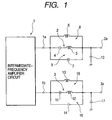
- An intermediate-frequency output circuit (hereinafter called an "IF output circuit") according to the present invention will be explained in accordance with Fig. 1.
- a television signal frequency-converted to an intermediate frequency signal by a mixer (not shown) of a television tuner is inputted to an intermediate-frequency amplifier circuit (hereinafter called an "IF amplifier circuit") 1.
- IF amplifier circuit an intermediate-frequency amplifier circuit
- the IF amplifier circuit 1 is comprised of a differential amplifier circuit and the like as a balanced amplifier circuit.
- a first intermediate-frequency tuning circuit (hereinafter called a "first IF tuning circuit") 2 is electrically connected to a first output terminal 1a of the IF amplifier circuit 1.
- a second intermediate-frequency tuning circuit (hereinafter called a “second TF tuning circuit”) 3 is electrically connected to a second output terminal 1b of the IF amplifier circuit 1.
- output terminals 2a and 3a of the IF tuning circuits 2 and 3 are electrically connected to an intermediate-frequency amplifier circuit (not shown) on the television receiver side.
- the first IF tuning circuit 2 comprises a capacitor 4 and a coil 5 whose one ends are electrically connected in series.
- a first coil 6 which serves as inductor means and a first capacitor 7 which serves as capacitor means, are electrically connected in parallel with the first IF tuning circuit 2.
- the first IF tuning circuit 2 and the first coil 6 constitute a first trap circuit 8. Further, the first IF tuning circuit 2 and the first capacitor 7 constitute a second trap circuit 9.
- a capacitor 10 is electrically connected between the output terminal 2a of the first IF tuning circuit 2 and the ground.
- the second IF tuning circuit 3 comprises a capacitor 11 and a coil 12 whose one ends are electrically connected in series.
- a second coil 13 which serves as inductor means and a second capacitor 14 which serves as capacitor means, are electrically connected in parallel with the second IF tuning circuit 3.
- a third trap circuit 15 is made up of the second IF tuning circuit 3 and the second coil 13. Further, a fourth trap circuit 16 is comprised of the second IF tuning circuit 3 and the second capacitor 14.
- a capacitor 17 is electrically connected between the output terminal 3a of the second IF tuning circuit 3 and the ground.
- a tuning frequency of the first IF tuning circuit 2 and a tuning frequency of the second IF tuning circuit 3 are set to a center frequency lying in an intermediate frequency band, e.g., nearly 36.15MHz in an European (German) television system.
- the first trap circuit 8 and the third trap circuit 15 trap frequencies lower than the center frequency in the intermediate frequency band, whereas the second trap circuit 9 and the fourth trap circuit 16 trap frequencies higher than the center frequency in the intermediate frequency band.
- the band per channel for a television signal lying in a VHF band is defined as 7MHz
- the band per channel for a television signal lying in a UHF band is defined as 8MHz.
- a voice intermediate-frequency signal (whose frequency: 40.4MHz) on one adjacent channel and a video intermediate-frequency signal (whose frequency: 31.9MHz) on the other adjacent channel are located in the vicinity of a video intermediate-frequency signal (whose frequency: 38.9MHz) and a voice intermediate-frequency signal (whose frequency: 33.4MHz) respectively.
- a voice intermediate-frequency signal (whose frequency: 41.4MHz) on one adjacent channel and a video intermediate-frequency signal (whose frequency: 30.9MHz) on the other adjacent channel are located in the vicinity of the video intermediate-frequency signal and the voice intermediate-frequency signal respectively.
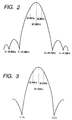
- the IF output circuit can obtain such a transmission characteristic as shown in Fig. 2. Even when either the television signal lying in the VHF band or the television signal lying in the UHF band is received with a simple circuit configuration, the IF output circuit can reduce interference produced due to the video intermediate-frequency signal and voice intermediate-frequency signal on the adjacent channels.
- the trap frequency of the first trap circuit 8 and the trap frequency of the third trap circuit 15 are designed so as to be equal to each other in advance, and the trap frequencies of the second trap circuit 9 and the fourth trap circuit 16 are designed so as to become equal to each other in advance.
- the video intermediate-frequency signal and voice intermediate-frequency signal on the adjacent channels can be attenuated greater.
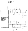
- the present IF output circuit can obtain such a transmission characteristic as illustrated in Fig. 3.
- the trap frequencies of the first through fourth trap circuits 8, 9, 15 and 16 may suitably be set in association with the video intermediate-frequency signal and voice intermediate-frequency signal on the adjacent channels.
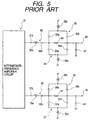
- Fig. 4 shows an output circuit except for the first capacitor 7 and second coil 13 employed in the intermediate-frequency output circuit shown in Fig. 1.
- Fig. 4 illustrates, for example, an IF output circuit suitable for a television system at the time that television signals lying within VHF and UHF bands are identical to each other in per-channel band (the band per channel corresponds to 6MHz in Japan, for example).
- a trap frequency of a first trap circuit 8 and a trap frequency of a fourth trap circuit 16 may be set in advance so as to take a frequency of a video intermediate-frequency signal on one adjacent channel and a frequency of a voice intermediate-frequency signal on the other adjacent channel, respectively.
- the present IF output circuit brings about such a transmission characteristic as illustrated in Fig. 3. Therefore, the IF output circuit can attenuate the video intermediate-frequency signal and the voice intermediate-frequency signal on the adjacent channels with a simpler circuit configuration.
- a first coil and a first capacitor are provided in parallel with a first intermediate-frequency tuning circuit.
- a second coil and a second capacitor are provided in parallel with a second intermediate-frequency tuning circuit.
- the first intermediate-frequency tuning circuit and the first coil constitute a first trap circuit.
- the first intermediate-frequency tuning circuit and the first capacitor constitute a second trap circuit
- the second intermediate-frequency tuning circuit and the second coil constitute a third trap circuit.
- the second intermediate-frequency tuning circuit and the second capacitor constitute a fourth trap circuit.
- the first trap circuit and the third trap circuit trap a video intermediate-frequency signal on a first adjacent channel and a video intermediate-frequency signal on a second adjacent channel
- the second trap circuit and the fourth trap circuit trap a voice intermediate-frequency signal on a first adjacent channel and a voice intermediate-frequency signal on a second adjacent channel.
- a trap frequency of the first trap circuit and a trap frequency of the third trap circuit are respectively set to the same frequency.
- a trap frequency of the second trap circuit and a trap circuit of the fourth trap circuit are set to the same frequency.
- the first trap circuit and the third trap circuit trap video intermediate-frequency signals on adjacent channels, whereas the second trap circuit and the fourth trap circuit trap voice intermediate-frequency signals on adjacent channels.
- a first intermediate-frequency tuning circuit in which a capacitor and a coil are electrically connected in series.
- An inductor is electrically connected in parallel with the first intermediate-frequency tuning circuit.
- One end of the first intermediate-frequency tuning circuit is electrically connected to a first output terminal of an intermediate-frequency amplifier circuit.
- a second intermediate-frequency tuning circuit is provided in which a capacitor and a coil are electrically connected in series. Capacitor means is electrically connected in parallel with the second intermediate-frequency amplifier circuit.
- One end of the second intermediate-frequency tuning circuit is electrically connected to a second output terminal of the intermediate-frequency amplifier circuit.
- Intermediate frequency signals are taken out from the other ends of the first intermediate-frequency tuning circuit and the second intermediate-frequency tuning circuit.
- the first intermediate-frequency tuning circuit and the inductor trap video intermediate-frequency signals on adjacent channels
- the second intermediate-frequency tuning circuit and the capacitor means trap voice intermediate-frequency signals on adjacent channels.
Landscapes
- Engineering & Computer Science (AREA)
- Power Engineering (AREA)
- Multimedia (AREA)
- Signal Processing (AREA)
- Filters And Equalizers (AREA)
- Input Circuits Of Receivers And Coupling Of Receivers And Audio Equipment (AREA)
Applications Claiming Priority (2)
| Application Number | Priority Date | Filing Date | Title |
|---|---|---|---|
| JP2091498A JP3562952B2 (ja) | 1998-02-02 | 1998-02-02 | 中間周波出力回路 |
| JP2091498 | 1998-02-02 |
Publications (2)
| Publication Number | Publication Date |
|---|---|
| EP0933932A1 true EP0933932A1 (de) | 1999-08-04 |
| EP0933932B1 EP0933932B1 (de) | 2003-05-21 |
Family
ID=12040501
Family Applications (1)
| Application Number | Title | Priority Date | Filing Date |
|---|---|---|---|
| EP19990300389 Expired - Lifetime EP0933932B1 (de) | 1998-02-02 | 1999-01-20 | Zwischenfrequenz-Ausgangsschaltung |
Country Status (3)
| Country | Link |
|---|---|
| EP (1) | EP0933932B1 (de) |
| JP (1) | JP3562952B2 (de) |
| DE (1) | DE69907984T2 (de) |
Cited By (1)
| Publication number | Priority date | Publication date | Assignee | Title |
|---|---|---|---|---|
| EP1244211A3 (de) * | 2001-03-22 | 2003-02-12 | Alps Electric Co., Ltd. | Zwischenfrequenzschaltung für Fernsehtuner |
Citations (4)
| Publication number | Priority date | Publication date | Assignee | Title |
|---|---|---|---|---|
| US4263619A (en) * | 1979-04-20 | 1981-04-21 | Rca Corporation | Double trapping of adjacent channel sound |
| US4875019A (en) * | 1988-07-21 | 1989-10-17 | Bahr Technologies, Inc. | Receiver preamplifier with tuned circuit adapted for Loran reception |
| US5148133A (en) * | 1991-05-29 | 1992-09-15 | Eagle Comtronics, Inc. | Quality factor improvement for filter applications |
| JPH1022788A (ja) * | 1996-07-02 | 1998-01-23 | Sharp Corp | チューナ |
-
1998
- 1998-02-02 JP JP2091498A patent/JP3562952B2/ja not_active Expired - Fee Related
-
1999
- 1999-01-20 EP EP19990300389 patent/EP0933932B1/de not_active Expired - Lifetime
- 1999-01-20 DE DE1999607984 patent/DE69907984T2/de not_active Expired - Lifetime
Patent Citations (4)
| Publication number | Priority date | Publication date | Assignee | Title |
|---|---|---|---|---|
| US4263619A (en) * | 1979-04-20 | 1981-04-21 | Rca Corporation | Double trapping of adjacent channel sound |
| US4875019A (en) * | 1988-07-21 | 1989-10-17 | Bahr Technologies, Inc. | Receiver preamplifier with tuned circuit adapted for Loran reception |
| US5148133A (en) * | 1991-05-29 | 1992-09-15 | Eagle Comtronics, Inc. | Quality factor improvement for filter applications |
| JPH1022788A (ja) * | 1996-07-02 | 1998-01-23 | Sharp Corp | チューナ |
Non-Patent Citations (1)
| Title |
|---|
| PATENT ABSTRACTS OF JAPAN vol. 098, no. 005 30 April 1998 (1998-04-30) * |
Cited By (2)
| Publication number | Priority date | Publication date | Assignee | Title |
|---|---|---|---|---|
| EP1244211A3 (de) * | 2001-03-22 | 2003-02-12 | Alps Electric Co., Ltd. | Zwischenfrequenzschaltung für Fernsehtuner |
| US6917390B2 (en) | 2001-03-22 | 2005-07-12 | Alps Electric Co., Ltd. | Intermediate-frequency coupled-circuit for television tuner |
Also Published As
| Publication number | Publication date |
|---|---|
| JPH11220670A (ja) | 1999-08-10 |
| DE69907984D1 (de) | 2003-06-26 |
| JP3562952B2 (ja) | 2004-09-08 |
| EP0933932B1 (de) | 2003-05-21 |
| DE69907984T2 (de) | 2004-01-08 |
Similar Documents
| Publication | Publication Date | Title |
|---|---|---|
| KR100268641B1 (ko) | 수신장치 | |
| EP1195889A2 (de) | Tuner | |
| US4490699A (en) | Intermediate frequency band-pass filter | |
| US4567523A (en) | Television receiver input circuit | |
| EP0194309A1 (de) | Frequenzumsetzer für kabelfernsehen mit verbesserten abstimmschaltungen | |
| EP0933932B1 (de) | Zwischenfrequenz-Ausgangsschaltung | |
| KR100211411B1 (ko) | 중앙 주파수 정보의 합성으로 fm 정보 라디오를 수신하는 텔레비젼 시스템 | |
| US6927805B2 (en) | Compactly-designed television receiver | |
| EP1124329A2 (de) | Eingangsschaltung eines Fernsehtuners | |
| JP3157372B2 (ja) | フィルタ | |
| EP0746904B1 (de) | Fernsehempfänger mit oberflächenwellenankopplung | |
| WO2003065580A1 (en) | Television tuner and printed circuit board used therein | |
| US4675634A (en) | Variable-capacitance tuning circuit for high-frequency signals | |
| JP3459728B2 (ja) | チューナ | |
| JP3283425B2 (ja) | チューナのトラップ回路 | |
| EP1536557B1 (de) | Zwischenfrequenzschaltkreis | |
| KR19990003858U (ko) | 더블 컨버젼 튜너 | |
| JP3290594B2 (ja) | テレビジョン受信機のトラップ回路装置 | |
| JPS6316187Y2 (de) | ||
| JP3360364B2 (ja) | バランス出力型チューナ装置の中間周波処理回路 | |
| JP3211616B2 (ja) | 高周波装置 | |
| JPH0119501Y2 (de) | ||
| KR820000768B1 (ko) | Vhf 튜우너의 단간동조 결합회로(段間同調結合回路) | |
| JP2008512922A (ja) | 複合チューナのための切換可能バンドトラッキング入力フィルタ | |
| JPS5927628A (ja) | Uhf電子同調受信装置 |
Legal Events
| Date | Code | Title | Description |
|---|---|---|---|
| PUAI | Public reference made under article 153(3) epc to a published international application that has entered the european phase |
Free format text: ORIGINAL CODE: 0009012 |
|
| AK | Designated contracting states |
Kind code of ref document: A1 Designated state(s): DE GB |
|
| AX | Request for extension of the european patent |
Free format text: AL;LT;LV;MK;RO;SI |
|
| 17P | Request for examination filed |
Effective date: 19990618 |
|
| AKX | Designation fees paid |
Free format text: DE GB |
|
| GRAH | Despatch of communication of intention to grant a patent |
Free format text: ORIGINAL CODE: EPIDOS IGRA |
|
| GRAH | Despatch of communication of intention to grant a patent |
Free format text: ORIGINAL CODE: EPIDOS IGRA |
|
| GRAA | (expected) grant |
Free format text: ORIGINAL CODE: 0009210 |
|
| AK | Designated contracting states |
Designated state(s): DE GB |
|
| REG | Reference to a national code |
Ref country code: GB Ref legal event code: FG4D |
|
| REF | Corresponds to: |
Ref document number: 69907984 Country of ref document: DE Date of ref document: 20030626 Kind code of ref document: P |
|
| PLBE | No opposition filed within time limit |
Free format text: ORIGINAL CODE: 0009261 |
|
| STAA | Information on the status of an ep patent application or granted ep patent |
Free format text: STATUS: NO OPPOSITION FILED WITHIN TIME LIMIT |
|
| 26N | No opposition filed |
Effective date: 20040224 |
|
| PGFP | Annual fee paid to national office [announced via postgrant information from national office to epo] |
Ref country code: GB Payment date: 20101215 Year of fee payment: 13 |
|
| PGFP | Annual fee paid to national office [announced via postgrant information from national office to epo] |
Ref country code: DE Payment date: 20110131 Year of fee payment: 13 |
|
| GBPC | Gb: european patent ceased through non-payment of renewal fee |
Effective date: 20120120 |
|
| PG25 | Lapsed in a contracting state [announced via postgrant information from national office to epo] |
Ref country code: GB Free format text: LAPSE BECAUSE OF NON-PAYMENT OF DUE FEES Effective date: 20120120 Ref country code: DE Free format text: LAPSE BECAUSE OF NON-PAYMENT OF DUE FEES Effective date: 20120801 |
|
| REG | Reference to a national code |
Ref country code: DE Ref legal event code: R119 Ref document number: 69907984 Country of ref document: DE Effective date: 20120801 |