EP0933918A2 - Aufwärmungssteuerung für Abtasterlichtquelle - Google Patents
Aufwärmungssteuerung für Abtasterlichtquelle Download PDFInfo
- Publication number
- EP0933918A2 EP0933918A2 EP99300633A EP99300633A EP0933918A2 EP 0933918 A2 EP0933918 A2 EP 0933918A2 EP 99300633 A EP99300633 A EP 99300633A EP 99300633 A EP99300633 A EP 99300633A EP 0933918 A2 EP0933918 A2 EP 0933918A2
- Authority
- EP
- European Patent Office
- Prior art keywords
- electrical
- power
- time
- exposure lamp
- scanner
- Prior art date
- Legal status (The legal status is an assumption and is not a legal conclusion. Google has not performed a legal analysis and makes no representation as to the accuracy of the status listed.)
- Withdrawn
Links
- 238000000034 method Methods 0.000 claims description 9
- 230000015556 catabolic process Effects 0.000 abstract description 5
- 238000006731 degradation reaction Methods 0.000 abstract description 5
- 238000005265 energy consumption Methods 0.000 abstract description 5
- 230000009467 reduction Effects 0.000 abstract description 5
- 230000008901 benefit Effects 0.000 description 7
- 230000003287 optical effect Effects 0.000 description 6
- 238000010586 diagram Methods 0.000 description 4
- 229910052724 xenon Inorganic materials 0.000 description 2
- FHNFHKCVQCLJFQ-UHFFFAOYSA-N xenon atom Chemical compound [Xe] FHNFHKCVQCLJFQ-UHFFFAOYSA-N 0.000 description 2
- 230000003466 anti-cipated effect Effects 0.000 description 1
- 230000000454 anti-cipatory effect Effects 0.000 description 1
- 230000008030 elimination Effects 0.000 description 1
- 238000003379 elimination reaction Methods 0.000 description 1
- 238000005286 illumination Methods 0.000 description 1
- 238000001228 spectrum Methods 0.000 description 1
- 230000000007 visual effect Effects 0.000 description 1
Images



Classifications
-
- H—ELECTRICITY
- H04—ELECTRIC COMMUNICATION TECHNIQUE
- H04N—PICTORIAL COMMUNICATION, e.g. TELEVISION
- H04N1/00—Scanning, transmission or reproduction of documents or the like, e.g. facsimile transmission; Details thereof
- H04N1/00885—Power supply means, e.g. arrangements for the control of power supply to the apparatus or components thereof
-
- H—ELECTRICITY
- H04—ELECTRIC COMMUNICATION TECHNIQUE
- H04N—PICTORIAL COMMUNICATION, e.g. TELEVISION
- H04N1/00—Scanning, transmission or reproduction of documents or the like, e.g. facsimile transmission; Details thereof
- H04N1/00885—Power supply means, e.g. arrangements for the control of power supply to the apparatus or components thereof
- H04N1/00888—Control thereof
- H04N1/00891—Switching on or off, e.g. for saving power when not in use
-
- H—ELECTRICITY
- H04—ELECTRIC COMMUNICATION TECHNIQUE
- H04N—PICTORIAL COMMUNICATION, e.g. TELEVISION
- H04N2201/00—Indexing scheme relating to scanning, transmission or reproduction of documents or the like, and to details thereof
- H04N2201/0008—Connection or combination of a still picture apparatus with another apparatus
- H04N2201/0074—Arrangements for the control of a still picture apparatus by the connected apparatus
Definitions
- the present patent document relates generally to optical scanning devices used to translate the contents of printed documents into electronic format, and more particularly to the control of electrical power to such devices.
- lamps have been incorporated into optical scanners in order to illuminate the item being scanned.
- choice of lamp type and style is often based upon cost, size, lamp life, light intensity, output spectrum, power requirements, and turn-on time.
- Such lamps include cold cathode fluorescent, hot cathode fluorescent, xenon, and light emitting diode (LED) light sources.
- cold cathode fluorescent lamps have an average lamp life of between 10,000 and 15,000 hours prior to burn-out. If a cold cathode lamp is on for only 1,000 hours per year, the operational life of the lamp is approximately 10 to 15 years, and even at 2,000 hours per year, it is 5 to 7.5 years.
- Representative embodiments of the teachings of the present patent document provide enhanced capabilities not previously available to aid in the immediate availability for scanning of optical scanning systems, while reducing degradation of lamp operational life and controlling energy consumption. These capabilities provide increased productivity for an operator of such systems.
- Representative embodiments of the present patent document incorporate a software program and associated circuitry for controlling the times when the scanner's exposure lamp is turned on.
- a timing circuit is used instead of the software program for controlling the times that the exposure lamp is on.
- the potential for a reduction in operator perceived lamp warm-up time thus exists, without requiring that the lamp be on continuously.
- the system can be set up such that the scanner is on and warmed-up when the operator arrives at work and is turned off after he leaves for the day.
- lamp and exposure lamp include not only lamps such as the cold cathode fluorescent, hot cathode fluorescent, and xenon lamps, but also other sources of illumination, such as light emitting diodes (LED's).
- FIGURE 1 is a block diagram of a scanner system with a software program and associated electronic circuitry for turning the scanner exposure lamp and scanner electronic circuitry on and off at selected times, the software program running on a computer.
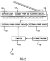
- FIGURE 2 is a block diagram of a scanner system with a software program and associated electronic circuitry for turning the scanner exposure lamp and scanner electronic circuitry on and off at selected times, the software program running on a computer.
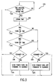
- FIGURE 3 is a flow chart of a representative embodiment of a computer software program for turning the scanner exposure lamp and associated electronic circuitry on and off at selected times.
- FIGURE 4 is a block diagram of a scanner system with a timer circuit and associated electronic circuitry for turning the scanner exposure lamp and scanner electronic circuitry on and off at selected times or intervals.
- FIGURE 5 is a block diagram of a scanner system with a timer circuit and associated electronic circuitry for turning the scanner exposure lamp and scanner electronic circuitry on and off at selected times or intervals.
- the present patent document relates to a novel apparatus for providing an optical scanner which is immediately available for scanning during selected times while reducing lamp operational life degradation.
- the operator can program the scanner to be warmed-up and ready to scan at a selected time and to turn off at a later selected time. These times could be associated, for example, with the operator's anticipated work arrival and departure times.
- an operator was forced to either incur excessively long warm-up times or, by leaving the lamp turned-on all the time, to incur significant reductions in lamp operational life with associated increased energy consumption when using optical scanning machines.
- like elements are identified with like reference numerals.
- a scanner system 100 comprises a computer 110 , running a software program 115 and connected electrically to an electrical-power-control circuit 120 .
- the software program directs the electrical-power-control-circuit 120 to connect electrical power from an electrical-power source 130 to an exposure lamp 145 and, in another embodiment, also to a scanner-power-and-electronic circuit 147 .
- Both the exposure lamp 140 and the scanner-power-and-electronic circuit 147 are components of a scanner 140 .
- the software program commands the electrical-power-control-circuit 120 to remove electrical power from the electrical-power source 130 from the exposure lamp 145 and, in yet another embodiment, also to remove electrical power from the scanner-power-and-electronic circuit 147 .
- the selected scanner turn-on time could be, for example, determined by the time the operator anticipates arriving at his office. And the selected scanner turn-off time could be determined by the time the operator anticipates leaving his office.
- a scanner system 100 comprises a computer 110 , running a software program 115 and connected electrically to an electrical-power-control circuit 120.
- the software program directs the electrical-power-control-circuit 120 to connect electrical power from an electrical-power source 130 to a scanner-power-and-electronic circuit 147 which in turn connects electrical power to an exposure lamp 145 .
- Both the exposure lamp 140 and the scanner-power-and-electronic circuit 147 are components of a scanner 140.
- the software program commands the electrical-power-control-circuit 120 to remove electrical power from the electrical-power source 130 from the scanner-power-and-electronic circuit 147 .
- the scanner-power-and-electronic circuit 147 in turn removes electrical power from the exposure lamp 145 .
- Figure 3 is a flow chart of a representative embodiment of a software program 115 for turning the exposure lamp 140, and in another embodiment the scanner-power-and-electronic circuit 147 .
- block 300 periodically checks the computer's clock to determine whether or not a selected time interval has passed since the software program 115 last determined whether or not it should send a command to either turn-on or turn-off the scanner. If the selected time interval has passed, block 300 passes control to block 305 .
- Block 305 obtains the computer clock's time and then passes control to block 310 .
- Block 310 compares the computer clock's time with the selected time at which the scanner should be turned-on. If the computer clock's time is greater than or equal to the selected time at which the scanner is to be turned-on, control is passed to block 315 , otherwise control is passed to block 320.
- Block 315 compares the computer clock's time with the selected time at which the scanner should be turned-off. If the computer clock's time is greater than or equal to the selected time at which the scanner is to be turned-off, control is passed to block 320, otherwise control is passed to block 330 .
- Block 320 determines whether or not the scanner is presently turned-off. If the scanner is presently turned-off, control is transferred to block 300 , otherwise control is transferred to block 325.
- Block 325 sends a command to turn-off power to the scanner. Block 325 then transfers control to block 300.
- Block 330 determines whether or not the scanner is presently turned-on. If the scanner is presently turned-on, control is transferred to block 300 , otherwise control is transferred to block 335 .
- Block 335 sends a command to turn-on power to the scanner. Block 335 then transfers control to block 300.
- a timing circuit 422 sends signals to an electrical-power-control circuit 120 at selected times or intervals. These signals force the electrical-power-control circuit 120 to connect electrical power from the electrical-power source 130 to the exposure lamp 145 , and in another embodiment also to a scanner-power-and-electronic circuit 147.
- a timing circuit 422 sends signals to an electrical-power-control circuit 120 at selected times or intervals. These signals force the electrical-power-control circuit 120 to connect electrical power from an electrical-power source 130 to a scanner-power-and-electronic circuit 147 .
- the scanner-power-and-electronic circuit 147 in turn connects electrical power to an exposure lamp 145.
- the electrical-power source 130 is the electric power provided by the wall electrical outlet of the building in which the scanner-system 100 is located.
- Embodiments of the present patent document can be used to advantage in scanner systems 100 which use any type of exposure lamp 145 having a non-instantaneous, turn on time.
- a cold cathode fluorescent lamp is often used in commercial scanning machines and is an example of the type of exposure lamp 145 which would benefit from the advantages of incorporating the techniques such as described in present patent document.
- a primary advantage of the embodiments, as described in the present patent document, over previous techniques is the reduction in or the elimination of time that the operator must wait for the exposure lamp to warm-up, while reducing lamp operational life degradation. Also, energy consumption is significantly less than if the scanner lamp is left on continuously. Additionally, if the exposure lamp is fully warmed-up prior to scanning, the quality of the image produced is enhanced.
- An added advantage is the fact that the above features can be obtained automatically, without operator action.
Landscapes
- Engineering & Computer Science (AREA)
- Multimedia (AREA)
- Signal Processing (AREA)
- Facsimile Scanning Arrangements (AREA)
- Light Sources And Details Of Projection-Printing Devices (AREA)
- Image Input (AREA)
Applications Claiming Priority (2)
| Application Number | Priority Date | Filing Date | Title |
|---|---|---|---|
| US16245 | 1998-01-30 | ||
| US09/016,245 US6433895B1 (en) | 1998-01-30 | 1998-01-30 | Warm-up controller for a scanner light-source |
Publications (2)
| Publication Number | Publication Date |
|---|---|
| EP0933918A2 true EP0933918A2 (de) | 1999-08-04 |
| EP0933918A3 EP0933918A3 (de) | 2001-06-20 |
Family
ID=21776136
Family Applications (1)
| Application Number | Title | Priority Date | Filing Date |
|---|---|---|---|
| EP99300633A Withdrawn EP0933918A3 (de) | 1998-01-30 | 1999-01-28 | Aufwärmungssteuerung für Abtasterlichtquelle |
Country Status (3)
| Country | Link |
|---|---|
| US (1) | US6433895B1 (de) |
| EP (1) | EP0933918A3 (de) |
| JP (1) | JPH11284804A (de) |
Cited By (1)
| Publication number | Priority date | Publication date | Assignee | Title |
|---|---|---|---|---|
| EP1104159A3 (de) * | 1999-11-25 | 2002-08-21 | Seiko Epson Corporation | Bildlesegerät |
Families Citing this family (5)
| Publication number | Priority date | Publication date | Assignee | Title |
|---|---|---|---|---|
| US6765700B1 (en) * | 1998-08-20 | 2004-07-20 | Canon Kabushiki Kaisha | Method for detecting and controlling home position of image reader |
| JP3630028B2 (ja) * | 1999-08-26 | 2005-03-16 | ブラザー工業株式会社 | 画像読取装置および記憶媒体 |
| JP3631100B2 (ja) * | 2000-04-27 | 2005-03-23 | キヤノン株式会社 | 画像読取装置、及び画像読取方法 |
| US7729017B2 (en) * | 2004-05-11 | 2010-06-01 | Lexmark International, Inc. | Scanning device and method for scanning |
| JP5020169B2 (ja) * | 2008-06-19 | 2012-09-05 | 京セラドキュメントソリューションズ株式会社 | 画像読取装置及びこれを備えた画像形成装置 |
Family Cites Families (8)
| Publication number | Priority date | Publication date | Assignee | Title |
|---|---|---|---|---|
| US4267439A (en) | 1979-12-12 | 1981-05-12 | Key Tronic Corporation | Document reader lamp life extension system |
| GB8900263D0 (en) | 1989-01-06 | 1989-03-08 | Pearpoint Ltd | Miniature tv camera systems |
| GB2231213A (en) * | 1989-02-24 | 1990-11-07 | Pyramid Power Systems Limited | An uninterruptible power supply for a facsimile machine |
| JPH04113768A (ja) | 1990-09-04 | 1992-04-15 | Sony Corp | ファクシミリ装置 |
| JPH04264870A (ja) | 1991-02-19 | 1992-09-21 | Toshiba Corp | ファクシミリ装置 |
| US5668446A (en) | 1995-01-17 | 1997-09-16 | Negawatt Technologies Inc. | Energy management control system for fluorescent lighting |
| US5636040A (en) * | 1995-08-01 | 1997-06-03 | Acer Peripherals, Inc. | Automatic intensity control of the lamp within image scanning apparatus |
| US6316767B1 (en) * | 1999-09-17 | 2001-11-13 | Hewlett-Packard Company | Apparatus to reduce wait time for scanner light-source warm-up |
-
1998
- 1998-01-30 US US09/016,245 patent/US6433895B1/en not_active Expired - Fee Related
-
1999
- 1999-01-18 JP JP11009191A patent/JPH11284804A/ja active Pending
- 1999-01-28 EP EP99300633A patent/EP0933918A3/de not_active Withdrawn
Cited By (2)
| Publication number | Priority date | Publication date | Assignee | Title |
|---|---|---|---|---|
| EP1104159A3 (de) * | 1999-11-25 | 2002-08-21 | Seiko Epson Corporation | Bildlesegerät |
| US6765696B1 (en) | 1999-11-25 | 2004-07-20 | Seiko Epson Corporation | Image reading apparatus |
Also Published As
| Publication number | Publication date |
|---|---|
| JPH11284804A (ja) | 1999-10-15 |
| US6433895B1 (en) | 2002-08-13 |
| EP0933918A3 (de) | 2001-06-20 |
Similar Documents
| Publication | Publication Date | Title |
|---|---|---|
| US6316767B1 (en) | Apparatus to reduce wait time for scanner light-source warm-up | |
| US6417937B1 (en) | Integrated automatic document feeder and active transparency adapter | |
| EP0949800A3 (de) | Bildlesegerät und Stever verfahren dafür | |
| US20040165233A1 (en) | Method of operating a double-sided scanner | |
| US6433895B1 (en) | Warm-up controller for a scanner light-source | |
| US20010033395A1 (en) | Image correction in image sensing system including image sensing apparatus and image processing apparatus | |
| JP2002134282A (ja) | 照明制御システム | |
| JP2007306078A (ja) | 画像読取装置、画像読取方法 | |
| JP2002314760A (ja) | 画像読取装置、および、画像読取方法 | |
| US20020015174A1 (en) | Image reading apparatus and its control method | |
| US8314977B2 (en) | Image reading device and image forming apparatus | |
| EP0912034A2 (de) | Vorhersagendes Aufwärmgerät für Abtasterlichtquelle | |
| JP3631100B2 (ja) | 画像読取装置、及び画像読取方法 | |
| US7315405B2 (en) | Image forming apparatus and image scanning method | |
| US6646770B2 (en) | Light-emitting diode light source control method | |
| JP4072976B2 (ja) | 画像読み取り装置 | |
| US20100134856A1 (en) | Method for selecting and adjusting scanner illuminant | |
| JP2013179386A (ja) | 画像読取装置及び画像読取方法 | |
| US20030169465A1 (en) | Image-scanning device | |
| JPS6232764A (ja) | 画像読取り装置 | |
| JP3992241B2 (ja) | 画像読み取り装置 | |
| JP3255732B2 (ja) | 画像読取装置 | |
| JP2001358910A (ja) | 画像読み取り装置、及びその制御方法並びに記憶媒体 | |
| JP2910806B2 (ja) | 画像読取装置 | |
| JPH03297266A (ja) | 画像読取装置 |
Legal Events
| Date | Code | Title | Description |
|---|---|---|---|
| PUAI | Public reference made under article 153(3) epc to a published international application that has entered the european phase |
Free format text: ORIGINAL CODE: 0009012 |
|
| AK | Designated contracting states |
Kind code of ref document: A2 Designated state(s): DE FR GB |
|
| AX | Request for extension of the european patent |
Free format text: AL;LT;LV;MK;RO;SI |
|
| RAP1 | Party data changed (applicant data changed or rights of an application transferred) |
Owner name: HEWLETT-PACKARD COMPANY, A DELAWARE CORPORATION |
|
| PUAL | Search report despatched |
Free format text: ORIGINAL CODE: 0009013 |
|
| AK | Designated contracting states |
Kind code of ref document: A3 Designated state(s): AT BE CH CY DE DK ES FI FR GB GR IE IT LI LU MC NL PT SE |
|
| AX | Request for extension of the european patent |
Free format text: AL;LT;LV;MK;RO;SI |
|
| 17P | Request for examination filed |
Effective date: 20010727 |
|
| AKX | Designation fees paid |
Free format text: DE FR GB |
|
| 17Q | First examination report despatched |
Effective date: 20020412 |
|
| STAA | Information on the status of an ep patent application or granted ep patent |
Free format text: STATUS: THE APPLICATION IS DEEMED TO BE WITHDRAWN |
|
| 18D | Application deemed to be withdrawn |
Effective date: 20040127 |