EP0933503A2 - Silencieux pour le canal d'échappement d'une turbine à gaz - Google Patents
Silencieux pour le canal d'échappement d'une turbine à gaz Download PDFInfo
- Publication number
- EP0933503A2 EP0933503A2 EP99100914A EP99100914A EP0933503A2 EP 0933503 A2 EP0933503 A2 EP 0933503A2 EP 99100914 A EP99100914 A EP 99100914A EP 99100914 A EP99100914 A EP 99100914A EP 0933503 A2 EP0933503 A2 EP 0933503A2
- Authority
- EP
- European Patent Office
- Prior art keywords
- gas turbine
- flow
- silencer according
- elements
- section
- Prior art date
- Legal status (The legal status is an assumption and is not a legal conclusion. Google has not performed a legal analysis and makes no representation as to the accuracy of the status listed.)
- Withdrawn
Links
- 230000003584 silencer Effects 0.000 title claims description 36
- 238000011144 upstream manufacturing Methods 0.000 claims description 8
- 230000001154 acute effect Effects 0.000 claims description 5
- 239000011358 absorbing material Substances 0.000 claims 1
- 239000007789 gas Substances 0.000 description 58
- 230000000694 effects Effects 0.000 description 7
- 239000000919 ceramic Substances 0.000 description 4
- 230000003068 static effect Effects 0.000 description 4
- 229910000831 Steel Inorganic materials 0.000 description 2
- 238000001816 cooling Methods 0.000 description 2
- 239000000835 fiber Substances 0.000 description 2
- 238000009434 installation Methods 0.000 description 2
- 238000009413 insulation Methods 0.000 description 2
- 239000010959 steel Substances 0.000 description 2
- 230000007704 transition Effects 0.000 description 2
- 230000005540 biological transmission Effects 0.000 description 1
- 230000003247 decreasing effect Effects 0.000 description 1
- 230000001419 dependent effect Effects 0.000 description 1
- 239000004744 fabric Substances 0.000 description 1
- 238000010304 firing Methods 0.000 description 1
- 238000010438 heat treatment Methods 0.000 description 1
- 239000000463 material Substances 0.000 description 1
- 238000000034 method Methods 0.000 description 1
- 238000004904 shortening Methods 0.000 description 1
Images
Classifications
-
- F—MECHANICAL ENGINEERING; LIGHTING; HEATING; WEAPONS; BLASTING
- F01—MACHINES OR ENGINES IN GENERAL; ENGINE PLANTS IN GENERAL; STEAM ENGINES
- F01D—NON-POSITIVE DISPLACEMENT MACHINES OR ENGINES, e.g. STEAM TURBINES
- F01D25/00—Component parts, details, or accessories, not provided for in, or of interest apart from, other groups
- F01D25/30—Exhaust heads, chambers, or the like
Definitions
- the invention relates to a silencer for a Gas turbine plant, as used in particular for energy generation is used with stationary systems.
- Modern power plants use at least steam generation partly gas turbine systems that are not only mechanical, energy that can be directly used by generators, but also emit a hot gas stream that can be used to generate energy via steam generators.
- gas turbine systems replace conventional firing systems completely or partially.
- Gas turbines point relatively at their outlet (exhaust) high gas speeds. Besides, that is Flow at least partially very turbulent and the Gas turbine gives a high sound level at its outlet from.
- the high flow rate at the exit of the Gas turbine has a very low static pressure Episode.
- a diffuser is usually used for this, which is characterized by a long, gradually widening channel is formed. To the To achieve the desired diffuser effect, the opening angle of the expanding channel not too big be. With the required cross sectional enlargements of the Flow channel leads this with common diffuser inlet cross sections to lengths of more than 10 m, e.g. 13 m.
- the invention solves this problem with a gas turbine silencer with the features of the claim 1.
- the gas turbine diffuser is part of the Silencer.
- This is achieved by the interior of the muffler by setting elements in preferably side by side diffuser channels is divided. These open in the flow direction, respectively the flow cross-section even at small opening angles relatively strong in percentage terms in each diffuser channel increases.
- the increase is significantly larger than one single diffuser channel with the same opening angle and correspondingly larger inlet cross-section. To this In this way, a double gain in space is achieved.
- a large Space is gained through the structural union of diffuser and muffler together.
- Another Significant shortening of the overall length is due to the division of the flow channel to many parallel, i.e. Diffuser channels connected to one another on the inlet and outlet side reached.
- the interior of the housing of the gas turbine silencer is through individual backdrop elements in diffuser channels divided.
- the backdrop elements effect one Orientation of the flow by following the flow path pretend.
- the backdrop elements for example.
- As a steel frame be built up with ceramic fibers is. It results from the structure of the ceramic mesh additionally a sound absorbing effect.
- the housing for example, at least partially on the inside with ceramic fabric be lined up for sound transmission to dampen outside.
- the backdrop elements preferably designed as a flow body, the gas flow has the lowest possible resistance oppose and if possible no additional vertebrae produce.
- the backdrop elements can, for example, as Plates should be formed, the thickness of which is upstream increases towards the downstream end, and the both on their upstream and on their downstream Are rounded at the end.
- the diffuser channels are, for example, slit-like trained, i.e. the fault cross section is indicated by a narrow rectangle formed, the short edge of which is downstream increases while the longer edge remains unchanged remains. In this way, with small opening angles, which allow a good diffuser effect, a percentage, relatively high, increase in cross section.
- the backdrop elements can also be a constant or different in the direction of flow have changing, for example decreasing thickness.
- the link elements can be ring-shaped, for example be designed as round or square elements. Again, it is possible to make the diffuser channels relative form narrow gaps, their thickness in the direction of flow increases. Thus, a good diffuser effect is short Length allowed.
- the backdrop elements are preferred in side view Rectangular plates with a horizontal flow direction in the gas turbine silencer essentially are arranged vertically.
- the backdrop elements are preferably held firmly on their underside. At their upper end they are only fixed laterally, moving up and down can. This avoids tension when heating up quickly and cooling. Especially when starting the gas turbines there is a very quick warm-up process. Through the one-sided mounting of the link elements becomes temperature tensions minimized.
- a grid is arranged, which with the 80 to 150 m / s divides flow delivered by the gas turbine.
- a grid element in each case a link element with, for example, a round cross section.
- the Lattice bar is at a distance of a few centimeters arranged in front of the front edge of the respective link element.
- the one as a flow divider or vortex breaker serving staff creates a slipstream, so to speak in which a set element is then arranged. The resulting flow resistance is less than for arrangements without flow dividers.
- the backdrop elements arranged obliquely (angle ⁇ ) to each other, but they are even wedge-shaped, that is, from the entrance to the exit thicker. This results in a good superimposition of the muffler effect with the diffuser effect and at the same time advantageous slow flow conditions at the exit.
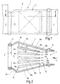
- a gas turbine silencer 1 is illustrated in FIG. 1, the one at the exit is only schematic and cut indicated gas turbine 2 one stationary power plant is connected and to a likewise only schematically and cut indicated steam generator 3 leads.
- the gas turbine silencer 1 serves the gas turbine 2 with leaving a speed of over 100 m / s Exhaust gases to calm down and slow them down with a Speed below 30 meters per second to the steam generator 3 deliver.
- the gas turbine silencer has 1 a housing 4 which encloses an interior 5. To avoid unwanted cooling the flowing through the gas turbine muffler 1 Exhaust gases from the gas turbine 2 is the housing 4 with a Insulating layer 6 provided for thermal insulation.
- the housing 4 like the side view in Figure 1 illustrates an almost constant height. However, the width of the housing 4 increases from that Gas turbine 2 to the steam generator 3, in particular Figure 2 illustrates.
- the housing 4 is at the gas turbine end provided with an entrance 7, the cross section of which is rectangular is. At the input 7 there is a compensator 8 arranged, the elastic expansion resiliently compensates.
- the compensator connects the output of the gas turbine 2 fluid-tight with the input 7 of the housing 4.
- the housing 4 is for connection to the steam generator 3 provided with an output 9 through a rectangular opening is also formed.
- a compensator 11 is arranged, the thermal conditional extensions between the steam generator 3 and balance the housing 4.
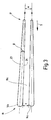
- the Link elements 14 are essentially mutually identically constructed, approximately plate-shaped elements that a steel frame with ceramic fiber layer.
- the Set elements 14 are standing in the interior 5 arranged and subdivide the interior 5 of one flow channel extending from the inlet 7 to the outlet 9 forms, into individual diffuser channels 15 (15a to 15f)
- the diffuser channels 15 are relatively narrow. While at its entrance, for example, a height of 4000 millimeters can have, they are only about 200 millimeters wide. They are therefore slit or slit-shaped.
- the individual diffuser elements in the direction of flow i.e. from their respective upstream End 17 towards its downstream end 18 thicker.
- Adjacent diffuser elements 14 are each enclosing an acute angle ⁇ arranged, which is preferably less than 7 °.
- the diffuser channel 15 expands accordingly fewer. Nevertheless, the percentage is high Increase in flow cross-section and thus a good one Slowdown and increase in pressure of the flowing Gas flow reached. Without scenery elements 14, the expanding interior 5 due to the muffler the divergence angle of the two side walls of the housing 4 of about 30 ° no longer act as a diffuser.
- the link elements 14 thus perform a double function. On the one hand, they define between each other Diffuser channels 15, on the other hand, they align the Gas turbine 2 incoming turbulent flow from and even out these.
- the diffuser element 14 has essentially flat side surfaces 23, 24 (FIG. 3) which together form an acute angle ⁇ . This is only a few degrees (for example 3 to 5 °). At its front or upstream end, the link element 14 is rounded off with a radius. Likewise, the link element 14 is rounded at its downstream or rear end 18 with a radius.
- each lattice bar 22 is a link element 14 assigned and at some distance from this arranged. The distance corresponds approximately to the thickness of the relevant backdrop element in the middle between its upstream end 17 and its downstream End 18.
- the bars have a round cross-section and are parallel to the backdrop elements aligned, i.e. they are to be thought in or in parallel Layers arranged by the side surfaces 23, 24 each Setting element 14 are set.
- an empty space serves as an exit space 25.
- the entry room 25 forms a branch in which the diffuser channels 15 are connected to each other on the input side forms the Exit area a merger or a collection area for the gases emerging from the diffuser channels 15.
- the gas turbine silencer 1 described so far works as follows:
- the gas turbine 2 comes into operation in the direction of flow S is a gas flow at high speed from, for example, 100 to 120 m / s.
- the gas flow occurs the entrance room 21 and first meets the Lattice bars 22.
- the flow is divided to itself to those defined between the backdrop elements 14 Split diffuser channels 15.
- the flow due to the small distances between the link elements 14 with each other on an essentially straight path forced and thus evened out.
- the pressure static Pressure
- the partial gas flows combine in the outlet space 25 of the diffuser channels 15a to 15f to form a total gas flow and exit at exit 9. This is correct essentially with the sum of the individual cross sections on the output side of the diffuser channels 15 match.
- the gas turbine silencer 1 has one in the flow direction S. a relatively large angle widening interior 5.
- This backdrop elements 14 are arranged between each other Diffuser channels 15 limit themselves each with a much smaller acute angle expand from below 7 °.
- the narrow, gap-like diffuser channels 15 cause, in addition to slowing down Gas flow and thus in addition to an increase in pressure noise reduction by reducing turbulence and an equalization and alignment of the Flow. Thanks to the additional function of the gas turbine silencer 1 as a diffuser can be required so far separate diffusers that take up a large amount of space have been eliminated.
Landscapes
- Engineering & Computer Science (AREA)
- Mechanical Engineering (AREA)
- General Engineering & Computer Science (AREA)
- Exhaust Silencers (AREA)
- Engine Equipment That Uses Special Cycles (AREA)
Applications Claiming Priority (2)
| Application Number | Priority Date | Filing Date | Title |
|---|---|---|---|
| DE19803161 | 1998-01-28 | ||
| DE19803161A DE19803161C2 (de) | 1998-01-28 | 1998-01-28 | Gasturbinenschalldämpfer mit Diffusor |
Publications (2)
| Publication Number | Publication Date |
|---|---|
| EP0933503A2 true EP0933503A2 (fr) | 1999-08-04 |
| EP0933503A3 EP0933503A3 (fr) | 1999-11-17 |
Family
ID=7855868
Family Applications (1)
| Application Number | Title | Priority Date | Filing Date |
|---|---|---|---|
| EP99100914A Withdrawn EP0933503A3 (fr) | 1998-01-28 | 1999-01-20 | Silencieux pour le canal d'échappement d'une turbine à gaz |
Country Status (6)
| Country | Link |
|---|---|
| US (1) | US6035964A (fr) |
| EP (1) | EP0933503A3 (fr) |
| CZ (1) | CZ28199A3 (fr) |
| DE (1) | DE19803161C2 (fr) |
| HU (1) | HUP9900197A2 (fr) |
| PL (1) | PL331069A1 (fr) |
Families Citing this family (15)
| Publication number | Priority date | Publication date | Assignee | Title |
|---|---|---|---|---|
| FR2787513B1 (fr) * | 1998-12-17 | 2001-01-19 | Turbomeca | Dispositif d'echappement multicanal de turbomachine traite acoustiquement |
| US6415887B1 (en) | 1999-11-26 | 2002-07-09 | Cr Patents, Inc. | Refractive wave muffler |
| DE10162161A1 (de) * | 2001-12-17 | 2003-07-03 | Emitec Emissionstechnologie | Vorrichtung und Verfahren zur Schalldämpfung im Abgassystem einer Verbrennungskraftmaschine |
| US6851514B2 (en) | 2002-04-15 | 2005-02-08 | Air Handling Engineering Ltd. | Outlet silencer and heat recovery structures for gas turbine |
| US6920959B2 (en) * | 2003-05-30 | 2005-07-26 | M & I Heat Transfer Products Ltd. | Inlet and outlet duct units for air supply fan |
| US7131514B2 (en) * | 2003-08-25 | 2006-11-07 | Ford Global Technologies, Llc | Noise attenuation device for a vehicle exhaust system |
| US7086498B2 (en) * | 2003-08-25 | 2006-08-08 | Ford Global Technologies, Llc | Noise attenuation device for a vehicle exhaust system |
| EP1574667B1 (fr) * | 2004-03-02 | 2013-07-17 | Siemens Aktiengesellschaft | Diffuseur pour compresseur |
| EP1732062B1 (fr) * | 2005-06-07 | 2013-08-14 | Alstom Technology Ltd | Silencieux |
| US7717229B2 (en) * | 2008-05-09 | 2010-05-18 | Siemens Energy, Inc. | Gas turbine exhaust sound suppressor and associated methods |
| US20150059312A1 (en) * | 2013-08-29 | 2015-03-05 | General Electric Company | Exhaust stack having a co-axial silencer |
| EP2947283B1 (fr) | 2014-05-23 | 2017-01-11 | GE Energy Products France SNC | Structure d'isolation thermo-acoustique pour échappement de machine tournante |
| US10260772B2 (en) * | 2016-02-24 | 2019-04-16 | VAW Systems Ltd. | Duct mounted sound attenuating baffle with an internally suspended mass layer |
| CN108458467B (zh) * | 2017-02-17 | 2020-11-10 | S.I.Pan公司 | 分离器以及包括该分离器的消声器 |
| US20250250922A1 (en) * | 2024-02-01 | 2025-08-07 | Solar Turbines Incorporated | Sound-attenuating devices |
Family Cites Families (7)
| Publication number | Priority date | Publication date | Assignee | Title |
|---|---|---|---|---|
| US3033307A (en) * | 1959-10-06 | 1962-05-08 | Industrial Acoustics Co | Noise attenuating apparatus |
| US3602333A (en) * | 1969-10-15 | 1971-08-31 | Chiyoda Chem Eng Construct Co | Silencer for suction or discharge of fluids under pressure |
| US3739872A (en) * | 1971-05-27 | 1973-06-19 | Westinghouse Electric Corp | Gas turbine exhaust system |
| US4287962A (en) * | 1977-11-14 | 1981-09-08 | Industrial Acoustics Company | Packless silencer |
| DE2855219A1 (de) * | 1978-12-21 | 1980-07-10 | Lentjes Dampfkessel Ferd | Schalldaempfer hinter gasturbinen- abhitzekessel |
| CH672004A5 (fr) * | 1986-09-26 | 1989-10-13 | Bbc Brown Boveri & Cie | |
| US5728979A (en) * | 1993-04-05 | 1998-03-17 | Air Handling Engineering Ltd. | Air handling structure for fan inlet and outlet |
-
1998
- 1998-01-28 DE DE19803161A patent/DE19803161C2/de not_active Expired - Fee Related
-
1999
- 1999-01-20 EP EP99100914A patent/EP0933503A3/fr not_active Withdrawn
- 1999-01-27 HU HU9900197A patent/HUP9900197A2/hu unknown
- 1999-01-27 PL PL99331069A patent/PL331069A1/xx unknown
- 1999-01-27 CZ CZ99281A patent/CZ28199A3/cs unknown
- 1999-01-28 US US09/238,442 patent/US6035964A/en not_active Expired - Fee Related
Non-Patent Citations (1)
| Title |
|---|
| None |
Also Published As
| Publication number | Publication date |
|---|---|
| US6035964A (en) | 2000-03-14 |
| DE19803161C2 (de) | 2000-03-16 |
| HU9900197D0 (en) | 1999-03-29 |
| EP0933503A3 (fr) | 1999-11-17 |
| HUP9900197A2 (hu) | 1999-09-28 |
| CZ28199A3 (cs) | 1999-08-11 |
| DE19803161A1 (de) | 1999-07-29 |
| PL331069A1 (en) | 1999-08-02 |
Similar Documents
| Publication | Publication Date | Title |
|---|---|---|
| EP0933503A2 (fr) | Silencieux pour le canal d'échappement d'une turbine à gaz | |
| DE60215307T2 (de) | Auslassschalldämpfer für Gasturbinen | |
| EP1367311B1 (fr) | Silencieux pour un tuyau d'écoulement, utilisé en particulier pour un carter d'admission de turbine | |
| EP2199725B1 (fr) | Structure d'un surface avec noyau de refroidissement par impact | |
| DE10064264B4 (de) | Anordnung zur Kühlung eines Bauteils | |
| EP2423599A2 (fr) | Procédé de fonctionnement d'un agencement de brûleur ainsi qu'agencement de brûleur destiné à l'exécution du procédé | |
| EP2992270B1 (fr) | Bouclier thermique | |
| DE3505256C2 (de) | Vorrichtung zum berührungsfreien Führen von Warenbahnen, insbesondere Metallbändern, mittels eines Gasmediums | |
| DE1628237A1 (de) | UEberschallgitter | |
| DE19622424A1 (de) | Rostelement und Rost mit Flüssigkeitskühlung | |
| EP0640745A1 (fr) | Procédé de refroidissement d'un composant | |
| DE102012013328A1 (de) | Vorrichtung zur Erzeugung von Fluidpulsen | |
| WO2001000965A1 (fr) | Composant, notamment aube de turbine, pouvant etre expose a un gaz chaud | |
| EP0108298B1 (fr) | Condenseur de turbine avec au minimum un conduit de dérivation de vapeur entrant dans le dôme | |
| EP3491186B1 (fr) | Module d'écoulement et procédé de production d'un module d'écoulement pour une caisse de tête d'une machine à papier | |
| EP1760400B1 (fr) | Elément de grille avec refroidissement à liquide | |
| DE102017212961A1 (de) | Fluidisches Bauteil | |
| DE102010045551A1 (de) | Abgasanlage | |
| EP1729900B1 (fr) | Dispositif pour refroidir des toles et des feuillards | |
| DE1929370A1 (de) | Verbrennungseinrichtung | |
| EP2174060B1 (fr) | Générateur de vapeur | |
| EP2829693A1 (fr) | Condensateur à turbine pour une turbine à vapeur | |
| DE102018105828A1 (de) | Vorrichtung zur Aufweitung eines Luftvolumenstroms | |
| EP2889451B1 (fr) | Dispositif de refroidissement d'une paroi d'un composant | |
| WO2013020829A1 (fr) | Station de dérivation de vapeur |
Legal Events
| Date | Code | Title | Description |
|---|---|---|---|
| PUAI | Public reference made under article 153(3) epc to a published international application that has entered the european phase |
Free format text: ORIGINAL CODE: 0009012 |
|
| AK | Designated contracting states |
Kind code of ref document: A2 Designated state(s): AT FI FR GB NL |
|
| AX | Request for extension of the european patent |
Free format text: AL;LT;LV;MK;RO;SI |
|
| PUAL | Search report despatched |
Free format text: ORIGINAL CODE: 0009013 |
|
| AK | Designated contracting states |
Kind code of ref document: A3 Designated state(s): AT BE CH CY DE DK ES FI FR GB GR IE IT LI LU MC NL PT SE |
|
| AX | Request for extension of the european patent |
Free format text: AL;LT;LV;MK;RO;SI |
|
| 17P | Request for examination filed |
Effective date: 19991202 |
|
| AKX | Designation fees paid |
Free format text: AT DE FI FR GB NL |
|
| RBV | Designated contracting states (corrected) |
Designated state(s): AT FI FR GB NL |
|
| RAP1 | Party data changed (applicant data changed or rights of an application transferred) |
Owner name: ALSTOM POWER BOILER GMBH |
|
| STAA | Information on the status of an ep patent application or granted ep patent |
Free format text: STATUS: THE APPLICATION IS DEEMED TO BE WITHDRAWN |
|
| 18D | Application deemed to be withdrawn |
Effective date: 20010801 |
|
| REG | Reference to a national code |
Ref country code: DE Ref legal event code: 8566 |
|
| REG | Reference to a national code |
Ref country code: HK Ref legal event code: WD Ref document number: 1021654 Country of ref document: HK |