EP0933331A2 - Evaporative concentration apparatus for waste water - Google Patents
Evaporative concentration apparatus for waste water Download PDFInfo
- Publication number
- EP0933331A2 EP0933331A2 EP98610045A EP98610045A EP0933331A2 EP 0933331 A2 EP0933331 A2 EP 0933331A2 EP 98610045 A EP98610045 A EP 98610045A EP 98610045 A EP98610045 A EP 98610045A EP 0933331 A2 EP0933331 A2 EP 0933331A2
- Authority
- EP
- European Patent Office
- Prior art keywords
- waste water
- evaporative concentration
- steam
- concentration apparatus
- evaporating
- Prior art date
- Legal status (The legal status is an assumption and is not a legal conclusion. Google has not performed a legal analysis and makes no representation as to the accuracy of the status listed.)
- Granted
Links
Images
Classifications
-
- F—MECHANICAL ENGINEERING; LIGHTING; HEATING; WEAPONS; BLASTING
- F25—REFRIGERATION OR COOLING; COMBINED HEATING AND REFRIGERATION SYSTEMS; HEAT PUMP SYSTEMS; MANUFACTURE OR STORAGE OF ICE; LIQUEFACTION SOLIDIFICATION OF GASES
- F25B—REFRIGERATION MACHINES, PLANTS OR SYSTEMS; COMBINED HEATING AND REFRIGERATION SYSTEMS; HEAT PUMP SYSTEMS
- F25B29/00—Combined heating and refrigeration systems, e.g. operating alternately or simultaneously
- F25B29/006—Combined heating and refrigeration systems, e.g. operating alternately or simultaneously of the sorption type system
-
- C—CHEMISTRY; METALLURGY
- C02—TREATMENT OF WATER, WASTE WATER, SEWAGE, OR SLUDGE
- C02F—TREATMENT OF WATER, WASTE WATER, SEWAGE, OR SLUDGE
- C02F1/00—Treatment of water, waste water, or sewage
- C02F1/02—Treatment of water, waste water, or sewage by heating
- C02F1/04—Treatment of water, waste water, or sewage by heating by distillation or evaporation
-
- B—PERFORMING OPERATIONS; TRANSPORTING
- B01—PHYSICAL OR CHEMICAL PROCESSES OR APPARATUS IN GENERAL
- B01D—SEPARATION
- B01D1/00—Evaporating
- B01D1/0094—Evaporating with forced circulation
-
- B—PERFORMING OPERATIONS; TRANSPORTING
- B01—PHYSICAL OR CHEMICAL PROCESSES OR APPARATUS IN GENERAL
- B01D—SEPARATION
- B01D3/00—Distillation or related exchange processes in which liquids are contacted with gaseous media, e.g. stripping
- B01D3/007—Energy recuperation; Heat pumps
-
- C—CHEMISTRY; METALLURGY
- C02—TREATMENT OF WATER, WASTE WATER, SEWAGE, OR SLUDGE
- C02F—TREATMENT OF WATER, WASTE WATER, SEWAGE, OR SLUDGE
- C02F1/00—Treatment of water, waste water, or sewage
- C02F1/02—Treatment of water, waste water, or sewage by heating
- C02F1/04—Treatment of water, waste water, or sewage by heating by distillation or evaporation
- C02F1/048—Purification of waste water by evaporation
-
- F—MECHANICAL ENGINEERING; LIGHTING; HEATING; WEAPONS; BLASTING
- F25—REFRIGERATION OR COOLING; COMBINED HEATING AND REFRIGERATION SYSTEMS; HEAT PUMP SYSTEMS; MANUFACTURE OR STORAGE OF ICE; LIQUEFACTION SOLIDIFICATION OF GASES
- F25B—REFRIGERATION MACHINES, PLANTS OR SYSTEMS; COMBINED HEATING AND REFRIGERATION SYSTEMS; HEAT PUMP SYSTEMS
- F25B27/00—Machines, plants or systems, using particular sources of energy
- F25B27/02—Machines, plants or systems, using particular sources of energy using waste heat, e.g. from internal-combustion engines
-
- F—MECHANICAL ENGINEERING; LIGHTING; HEATING; WEAPONS; BLASTING
- F25—REFRIGERATION OR COOLING; COMBINED HEATING AND REFRIGERATION SYSTEMS; HEAT PUMP SYSTEMS; MANUFACTURE OR STORAGE OF ICE; LIQUEFACTION SOLIDIFICATION OF GASES
- F25B—REFRIGERATION MACHINES, PLANTS OR SYSTEMS; COMBINED HEATING AND REFRIGERATION SYSTEMS; HEAT PUMP SYSTEMS
- F25B15/00—Sorption machines, plants or systems, operating continuously, e.g. absorption type
- F25B15/02—Sorption machines, plants or systems, operating continuously, e.g. absorption type without inert gas
- F25B15/06—Sorption machines, plants or systems, operating continuously, e.g. absorption type without inert gas the refrigerant being water vapour evaporated from a salt solution, e.g. lithium bromide
-
- Y—GENERAL TAGGING OF NEW TECHNOLOGICAL DEVELOPMENTS; GENERAL TAGGING OF CROSS-SECTIONAL TECHNOLOGIES SPANNING OVER SEVERAL SECTIONS OF THE IPC; TECHNICAL SUBJECTS COVERED BY FORMER USPC CROSS-REFERENCE ART COLLECTIONS [XRACs] AND DIGESTS
- Y02—TECHNOLOGIES OR APPLICATIONS FOR MITIGATION OR ADAPTATION AGAINST CLIMATE CHANGE
- Y02A—TECHNOLOGIES FOR ADAPTATION TO CLIMATE CHANGE
- Y02A30/00—Adapting or protecting infrastructure or their operation
- Y02A30/27—Relating to heating, ventilation or air conditioning [HVAC] technologies
- Y02A30/274—Relating to heating, ventilation or air conditioning [HVAC] technologies using waste energy, e.g. from internal combustion engine
-
- Y—GENERAL TAGGING OF NEW TECHNOLOGICAL DEVELOPMENTS; GENERAL TAGGING OF CROSS-SECTIONAL TECHNOLOGIES SPANNING OVER SEVERAL SECTIONS OF THE IPC; TECHNICAL SUBJECTS COVERED BY FORMER USPC CROSS-REFERENCE ART COLLECTIONS [XRACs] AND DIGESTS
- Y02—TECHNOLOGIES OR APPLICATIONS FOR MITIGATION OR ADAPTATION AGAINST CLIMATE CHANGE
- Y02A—TECHNOLOGIES FOR ADAPTATION TO CLIMATE CHANGE
- Y02A40/00—Adaptation technologies in agriculture, forestry, livestock or agroalimentary production
- Y02A40/90—Adaptation technologies in agriculture, forestry, livestock or agroalimentary production in food processing or handling, e.g. food conservation
- Y02A40/963—Off-grid food refrigeration
-
- Y—GENERAL TAGGING OF NEW TECHNOLOGICAL DEVELOPMENTS; GENERAL TAGGING OF CROSS-SECTIONAL TECHNOLOGIES SPANNING OVER SEVERAL SECTIONS OF THE IPC; TECHNICAL SUBJECTS COVERED BY FORMER USPC CROSS-REFERENCE ART COLLECTIONS [XRACs] AND DIGESTS
- Y02—TECHNOLOGIES OR APPLICATIONS FOR MITIGATION OR ADAPTATION AGAINST CLIMATE CHANGE
- Y02B—CLIMATE CHANGE MITIGATION TECHNOLOGIES RELATED TO BUILDINGS, e.g. HOUSING, HOUSE APPLIANCES OR RELATED END-USER APPLICATIONS
- Y02B30/00—Energy efficient heating, ventilation or air conditioning [HVAC]
- Y02B30/52—Heat recovery pumps, i.e. heat pump based systems or units able to transfer the thermal energy from one area of the premises or part of the facilities to a different one, improving the overall efficiency
-
- Y—GENERAL TAGGING OF NEW TECHNOLOGICAL DEVELOPMENTS; GENERAL TAGGING OF CROSS-SECTIONAL TECHNOLOGIES SPANNING OVER SEVERAL SECTIONS OF THE IPC; TECHNICAL SUBJECTS COVERED BY FORMER USPC CROSS-REFERENCE ART COLLECTIONS [XRACs] AND DIGESTS
- Y02—TECHNOLOGIES OR APPLICATIONS FOR MITIGATION OR ADAPTATION AGAINST CLIMATE CHANGE
- Y02P—CLIMATE CHANGE MITIGATION TECHNOLOGIES IN THE PRODUCTION OR PROCESSING OF GOODS
- Y02P70/00—Climate change mitigation technologies in the production process for final industrial or consumer products
- Y02P70/10—Greenhouse gas [GHG] capture, material saving, heat recovery or other energy efficient measures, e.g. motor control, characterised by manufacturing processes, e.g. for rolling metal or metal working
Definitions
- the present invention relates to an evaporative concentration apparatus for waste water and, more particularly, to an evaporative concentration apparatus for waste water in which evaporative concentration of flue gas desulfurization waste water discharged from a flue gas desulfurization plant can be carried out very efficiently and stably, and a small-scale facility and the like are possible.
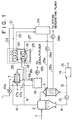
- Waste water 1 is introduced into an evaporating vessel 2 or into an inlet line of a heater 3 for a concentrated liquid 9, and mixed with an in-vessel liquid.
- the mixed in-vessel liquid is drawn from the lower part of the evaporating vessel 2 by means of a circulating pump 10 and sent to the heater 3 as the concentrated liquid 9, and a surplus concentrated liquid 12 is sent to a concentrated liquid tank 11.
- the concentrated liquid 12 sent to the concentrated liquid tank 11 is further treated by a solidifier 14 as a concentrated liquid 12b, and discharged to the outside of the system as a harmless solid matter 15.
- generated steam 6 discharged by the evaporation of the in-vessel liquid is sent to a cooler 7.
- the concentrated liquid 9 sent to the heater 3 is heated while passing through a heating tube in the heater 3.
- the heater 3 is a multitubular cylindrical heat exchanger, in which heating steam 4 introduced to a shell of the heater 3 is condensed by the absorption of latent heat caused by heat exchange, and discharged to the outside of the system as condensate 5 through a steam trap.
- the concentrated liquid 9 having passed through the heater 3 is allowed to flow back to the evaporating vessel 2, and the evaporative concentration is repeated.
- the generated steam 6 generated in the evaporating vessel 2 is sent to the cooler 7, and cooled into condensed water 8 in a shell of the cooler 7.
- Cooling water (cold) passes through a cooling tube of the cooler 7.
- the cooling water is discharged to the outside of the cooler as cooling water (warm).
- the cooling water (warm) is cooled into cold water (cold) again by a cooling tower or the like, and used in a circulating manner.
- Noncondensable gas generated in the cooler 7 is sucked by a vacuum pump 13 and discharged to the atmosphere.
- the noncondensible gas means a gas that is not liquefied by cooling.
- Desulfurization waste water 1 is saturated with gypsum, so that the temperature of the heating steam 4 must be not higher than 75°C to prevent scale generation. Therefore, the heating steam 4 must be low-temperature steam.
- the generated steam 6 generated form the evaporating vessel 2 condenses in the cooler, and is recovered to a desulfurizer as condensed water 8.
- the waste water in the evaporating vessel 2 is heated by the heat of the heating steam sent from the heater 3.
- the generated steam 6 heated in the evaporating vessel 2 is condensed by cooling water in the cooler 7 by heat exchange, and the exchanged heat is dissipated to the atmosphere as heat of evaporation in a cooling tower.
- most the heat of the heating steam is thrown away to the atmosphere as heat of evaporation in a cooling tower.
- the prior art has a drawback in that the quantity of the heating steam sent from the heater 3 is very large.
- the conventional evaporative concentration apparatus has a problem in that the thermal energy supplied to the heater 3 as steam is discharged to the atmosphere, so that new thermal energy is required to send the steam 4 to the heater 3 again.
- an evaporative concentration apparatus for waste water having an evaporating vessel and a heater for circular heating, in which the whole or part of thermal energy of generated steam discharged from the evaporating vessel is recovered by an absorption heat pump, and the thermal energy is supplied to the heater.
- the present invention was completed from such a viewpoint.
- the present invention provides an evaporative concentration apparatus for waste water having an evaporating vessel for evaporatively concentrating waste water and a heater for circularly heating an in-vessel liquid in the evaporating vessel, in which the whole or part of thermal energy of generated steam discharged from the evaporating vessel is recovered by an absorption heat pump, and the thermal energy is supplied to the heater.
- the absorption heat pump use water (H 2 O) as a refrigerant and lithium bromide (LiBr) solution as an absorbent (absorbing liquid), and include an evaporator for evaporating a refrigerant by the thermal energy from the generated steam, an absorber for absorbing the refrigerant steam in the absorbent, and a regenerator for making the absorbent concentrated by evaporating the refrigerant from the absorbent by using a driving heat source so as to be made reusable in the absorber.
- the absorption heat pump may be provided with a condenser for heating circulating warm water again by using the refrigerant steam generated in the regenerator.
- the driving heat source should be steam, or fuel combustion direct fire or combustion gas
- the pressure in the evaporating vessel should be lower than the atmospheric pressure.
- the evaporative concentration apparatus in accordance with the present invention is most effective in the case where the waste water evaporatively concentrated by the evaporating vessel is wet type desulfurization waste water when sulfur oxides in combustion exhaust gas of coal or oil are removed.
- the heating steam quantity necessary for evaporative concentration of waste water can be decreased significantly as compared with the conventional apparatus. Also, the capacity of cooler and cooling tower facility necessary for condensation of generated steam from the evaporating vessel can be reduced significantly as compared with the conventional apparatus.
- the condensate of steam of driving heat source is clean without being polluted, so that it can be sent back to a steam generating plant for reuse.
- reference numeral 1 denotes desulfurization waste water
- 2 denotes an evaporating vessel
- 3 denotes a heater
- 4 denotes steam
- 5 denotes condensate
- 6 denotes generated steam
- 7 denotes a cooler
- 8a and 8b denote condensed water
- 9 denotes concentrated liquid
- 10 denotes a circulating pump
- 11 denotes a concentrated liquid tank
- 13a denotes a vacuum pump
- 13b denotes a pump
- 14 denotes a solidifier
- 15 denotes a solid matter
- 16 denotes a condensed water tank
- 17a denotes cooling water (cold)
- 17b denotes cooling water (warm)
- 18 denotes an evaporator
- 19 denotes an absorber
- 20 denotes a regenerator
- 21 denotes plant steam
- 22 denotes condensate
- 23 denotes heated
- the whole or part of thermal energy of generated steam discharged from an evaporating vessel is recovered by an absorption heat pump, and the thermal energy is supplied to a heater.
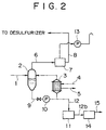
- waste water 1 is introduced into an evaporating vessel 2 and mixed with an in-vessel liquid.
- the mixed in-vessel liquid is heated by a circulating liquid sent from a heater 3, and part of water is evaporated and concentrated.
- the concentrated in-vessel liquid is drawn from the lower part of the evaporating vessel 2 by means of a circulating pump 10, and sent to the heater 3 as a concentrated liquid 9.
- a surplus concentrated liquid 12 is discharged to the outside of the system, and treated into a harmless solid matter by a solidifier 14 or the like.
- the whole or part of generated steam 6 discharged by the evaporation of in-vessel liquid is sent to an absorption heat pump 29, and other part thereof is sent to a cooler 7.
- the concentrated liquid 9 sent to the heater 3 is heated by heat exchange while passing through a heating tube of the heater 3.
- circulating warm water (warm) 25a introduced to a shell of the heater 3 is cooled by the absorption of latent heat caused by heat exchange, turning to circulating warm water (cold) 25b.
- Most of the circulating warm water (cold) 25b is sent to the absorption heat pump 29, and other part thereof is sent to a steam generating plant.
- the circulating warm water 25a supplied to the heater 3 should preferably be warm water having a saturation temperature of 70 to 80°C.
- the operating conditions in the evaporating vessel 2 are set as follows:
- the evaporation temperature is lower than 45°C, the interior of the evaporating vessel 2 must be made high vacuum, so that there arises a problem in that a high-performance vacuum pump is needed, which is uneconomical. If it exceeds 90°C, there is a drawback in that gypsum scale increases, and the calorie for heating during the evaporative concentration increases.
- the whole or part of the generated steam 6 generated in the evaporating vessel 2 is sent to the absorption heat pump 29.
- the absorption heat pump 29 which usually uses water as a refrigerant and lithium bromide solution as an absorbent, includes a refrigerant evaporator 18 for evaporating a refrigerant by the thermal energy from the generated steam 6, an absorber 19 for absorbing refrigerant steam in the absorbent, and regenerator 20 for making the absorbent concentrated by evaporating the refrigerant from the absorbent so as to be made reusable in the absorber. Also, it is preferable that the absorption heat pump 29 be provided with a condenser 28 for heating circulating warm water 27 again by the refrigerant steam generated in the regenerator.
- the whole or part of the generated steam 6 is introduced to the evaporator 18 in the absorption heat pump 29.
- the evaporator 18 water is heated by the generated steam 6, refrigerant steam at a low temperature is generated, and the refrigerant steam is supplied to the absorber 19.
- the introduced generated steam 6 dissipates thermal energy for the refrigerant evaporation and is condensed in the evaporator 18, and then is discharged from the evaporator 18 as a condensed liquid 8b.
- the aforesaid absorber 19 is supplied with low-pressure refrigerant steam generated in the evaporator 18 and a concentrated absorbent from the regenerator 20.
- the concentrated absorbent of lithium bromide absorbs the low-pressure refrigerant steam and turns to a dilute solution, and the absorption heat is discharged. That is, the refrigerant steam is absorbed in a concentrated absorbent with high lithium bromide concentrations while holding steam enthalpy.
- the aforesaid dilute solution with low lithium bromide concentrations is sent to the regenerator 20, and heated by plant steam 21 in the regenerator 20. By this heating, the refrigerant steam (water vapor) in the dilute solution is evaporated, and supplied to the condenser 28. Also, the dilute solution is concentrated into a concentrated absorbent with high lithium bromide concentrations. This concentrated absorbent is supplied again to the absorber 19.
- the circulating warm water 27 is introduced into the absorber 19 and heated by the absorption heat, and further is introduced into the condenser 28, where it is heated again by the refrigerant steam. Then, the circulating warm water 27 is discharged from the condenser 28 as high-temperature heated water 23.
- the thermal energy given to the heated water 23 usually reaches about 1.7 times the calorie of the plant steam 21, and the temperature thereof usually reaches 70 to 90°C depending on the quantity and temperature of the heated water 23.
- the refrigerant steam (water vapor) having heated the circulating warm water 27 in the condenser 28 is condensed into water, and supplied to the evaporator 18 as necessary. Also, the dilute solution having absorbed the low-pressure refrigerant steam in the absorber 19 is supplied to the regenerator 20.
- the heated water 23 heated two times in the absorption heat pump is sent to a circulating water tank 24, and combined with condensate 22 of the plant steam 21 in the tank 24.
- the warm water in the circulating water tank 24 is sent to the heater 3 as the circulating warm water (warm) 25a by a pump 26a.
- the circulating warm water 25a introduced into the heater 3 is cooled by the absorption of latent heat caused by heat exchange, and flows out as the circulating warm water (cold) 25b. Part thereof is sent to the absorption heat pump 29 as the circulating warm water 27, and other part is sent to the steam generating plant.
- cooling water (cold) flows through, cools the generated steam 6 by heat exchange, and then is discharged to the outside of the apparatus as cooling water (warm) 17b. Thereafter, the cooling water (warm) 17b is cooled into the cooling water (cold) again by a cooling tower or the like, by which it is used for circulation.
- the noncondensible gas generated in the cooler 7 is sucked by a vacuum pump 13a, and discharged to the atmosphere.
- the noncondensible gas means a gas that is not liquefied by cooling.
- the condensed water 8a sent from the cooler 7 is introduced into a condensed water tank 16 together with the condensed water 8b sent from the absorption heat pump 29.
- the generated noncondensible gas is sucked by the vacuum pump 13a and discharged to the atmosphere.
- the condensed water in the condensed water tank 16 is sent to a desulfurizer by means of a pump 13b.
- the evaporative concentration apparatus for waste water in accordance with the present invention is not limited to the above embodiment, and can be modified variously in the scope of the technical concept of the present invention.
- evaporative concentration can be effected efficiently in an evaporating vessel by effectively utilizing the thermal energy of generated steam, and also the operation of evaporative concentration apparatus can be performed stably by stably securing heating steam quantity.
- the thermal energy obtained from generated steam is taken out to heat circulating warm water, by which heating steam used for a heater can be supplied efficiently in large quantities.
- new heating steam quantity necessary for evaporative concentration of waste water can be decreased significantly (about 40 to 50%) as compared with the conventional apparatus.
- the evaporative concentration apparatus can be operated stably, and the evaporative concentration ratio of waste water can be kept constant.
- the capacity of cooler and cooling tower facility necessary for condensation of generated steam from an evaporating vessel can be reduced significantly (about 40 to 50%) as compared with the conventional apparatus.
- the condensate of steam of driving heat source is clean without being polluted, so that it can be sent back to a steam generating plant for reuse.
Landscapes
- Engineering & Computer Science (AREA)
- Chemical & Material Sciences (AREA)
- Chemical Kinetics & Catalysis (AREA)
- Physics & Mathematics (AREA)
- General Engineering & Computer Science (AREA)
- Thermal Sciences (AREA)
- Mechanical Engineering (AREA)
- Organic Chemistry (AREA)
- Environmental & Geological Engineering (AREA)
- Hydrology & Water Resources (AREA)
- Water Supply & Treatment (AREA)
- Life Sciences & Earth Sciences (AREA)
- Combustion & Propulsion (AREA)
- Heat Treatment Of Water, Waste Water Or Sewage (AREA)
- Vaporization, Distillation, Condensation, Sublimation, And Cold Traps (AREA)
- Treating Waste Gases (AREA)
Abstract
Description
- Evaporation temperature
- Normally 45 to 90°C
Preferably 50 to 70°C - Evaporated steam pressure
- Normally 70 to 530 Torr
Preferably 90 to 190 Torr
Claims (9)
- An evaporative concentration apparatus for waste water having an evaporating vessel for evaporatively concentrating waste water and a heater for circularly heating an in-vessel liquid in said evaporating vessel, in which the whole or part of thermal energy of generated steam discharged from said evaporating vessel is recovered by an absorption heat pump, and said thermal energy is supplied to said heater.
- An evaporative concentration apparatus for waste water according to claim (1), wherein said absorption heat pump, which uses water as a refrigerant and lithium bromide solution as an absorbent, includes an evaporator for evaporating a refrigerant by the thermal energy from said generated steam, an absorber for absorbing said refrigerant steam in the absorbent, and a regenerator for making the absorbent concentrated by evaporating the refrigerant from said absorbent by using a driving heat source so as to be made reusable in said absorber.
- An evaporative concentration apparatus for waste water according to claim (1) or (2), wherein said driving heat source is steam, fuel combustion direct fire or fuel combustion gas.
- An evaporative concentration apparatus for waste water according to claim (1) or (2), wherein said driving heat source is steam, and the thermal energy of condensed water obtained by condensing said steam by using said absorption heat pump is supplied to said heater.
- An evaporative concentration apparatus for waste water according to claim (1), wherein the pressure in said evaporating vessel is lower than the atmospheric pressure.
- An evaporative concentration apparatus for waste water according to claim (1) or (2), wherein the waste water evaporatively concentrated by said evaporating vessel is wet type desulfurization waste water when sulfur oxides in combustion exhaust gas of coal or oil are removed.
- An evaporative concentration apparatus for waste water according to claim (3), wherein the waste water evaporatively concentrated by said evaporating vessel is wet type desulfurization waste water when sulfur oxides in combustion exhaust gas of coal or oil are removed.
- An evaporative concentration apparatus for waste water according to claim (4), wherein the waste water evaporatively concentrated by said evaporating vessel is wet type desulfurization waste water when sulfur oxides in combustion exhaust gas of coal or oil are removed.
- An evaporative concentration apparatus for waste water according to claim (5), wherein the waste water evaporatively concentrated by said evaporating vessel is wet type desulfurization waste water when sulfur oxides in combustion exhaust gas of coal or oil are removed.
Applications Claiming Priority (2)
| Application Number | Priority Date | Filing Date | Title |
|---|---|---|---|
| JP1533998 | 1998-01-28 | ||
| JP01533998A JP3448201B2 (en) | 1998-01-28 | 1998-01-28 | Wastewater evaporative concentrator |
Publications (3)
| Publication Number | Publication Date |
|---|---|
| EP0933331A2 true EP0933331A2 (en) | 1999-08-04 |
| EP0933331A3 EP0933331A3 (en) | 1999-12-15 |
| EP0933331B1 EP0933331B1 (en) | 2005-03-23 |
Family
ID=11886040
Family Applications (1)
| Application Number | Title | Priority Date | Filing Date |
|---|---|---|---|
| EP98610045A Expired - Lifetime EP0933331B1 (en) | 1998-01-28 | 1998-11-27 | Evaporative concentration apparatus for waste water |
Country Status (8)
| Country | Link |
|---|---|
| US (1) | US6076369A (en) |
| EP (1) | EP0933331B1 (en) |
| JP (1) | JP3448201B2 (en) |
| KR (1) | KR100315299B1 (en) |
| CN (1) | CN1130312C (en) |
| DK (1) | DK0933331T3 (en) |
| ES (1) | ES2236884T3 (en) |
| TW (1) | TW541287B (en) |
Cited By (2)
| Publication number | Priority date | Publication date | Assignee | Title |
|---|---|---|---|---|
| EP2109114A3 (en) * | 2008-03-12 | 2010-04-21 | Areva NP GmbH | Method and system for separating a neutron absorber from a coolant used in a coolant system |
| CN102353178A (en) * | 2011-09-01 | 2012-02-15 | 吴健 | Lithium bromide absorptive refrigeration air conditioner and sanitary hot water system driven by solar energy |
Families Citing this family (35)
| Publication number | Priority date | Publication date | Assignee | Title |
|---|---|---|---|---|
| JP4587197B2 (en) * | 2003-11-25 | 2010-11-24 | バブコック日立株式会社 | Wet flue gas desulfurization method and apparatus |
| JP4593191B2 (en) * | 2004-06-21 | 2010-12-08 | 月島環境エンジニアリング株式会社 | Cleaning method of heat exchanger in incinerator |
| KR20060109619A (en) * | 2005-04-18 | 2006-10-23 | 최명호 | Evaporation High Concentration Wastewater Treatment System and Method |
| CN101799207B (en) * | 2010-03-05 | 2012-01-04 | 清华大学 | System and method for recycling waste heat of bath sewage by utilizing absorption heat pump |
| PL406241A1 (en) * | 2011-01-27 | 2014-05-12 | 1Nsite Technologies Ltd. | Compact modular portable vaporizer for the SAGD process |
| US10378800B2 (en) * | 2011-09-23 | 2019-08-13 | Lennox Industries Inc. | Multi-staged water manifold system for a water source heat pump |
| CA2790732C (en) | 2011-09-26 | 2020-03-10 | Lennox Industries Inc. | Multi-staged water manifold system for a water source heat pump |
| CN102344179A (en) * | 2011-09-29 | 2012-02-08 | 中国科学院广州能源研究所 | Solar absorption type sea water desalination device with regenerative cycle |
| CN102910692A (en) * | 2012-10-18 | 2013-02-06 | 东南大学 | Device and method for realizing sea water desalination and heat supply by utilizing open-type absorption heat pump |
| EP2959250B1 (en) * | 2013-02-19 | 2021-12-15 | Natural Systems Utilities, Llc | Systems and methods for recovering energy from wastewater |
| US9724638B2 (en) | 2014-01-02 | 2017-08-08 | General Electric Technology Gmbh | Apparatus and method for evaporating waste water and reducing acid gas emissions |
| US9352274B2 (en) | 2014-01-02 | 2016-05-31 | Alstom Technology Ltd | Apparatus and method for evaporating waste water and reducing acid gas emissions |
| CN103727700A (en) * | 2014-01-06 | 2014-04-16 | 杭州沃润节能科技有限公司 | Waste heat recovering system aiming at discontinuous and impure waste water resources |
| CN103727512A (en) * | 2014-01-06 | 2014-04-16 | 杭州沃润节能科技有限公司 | Waste heat recovering system capable of continuously generating steam aiming at impure waste water resources |
| CN103712368A (en) * | 2014-01-06 | 2014-04-09 | 杭州沃润节能科技有限公司 | Waste heat recovery system aiming at discontinuous waste water source and discontinuous process water |
| CN103727699A (en) * | 2014-01-06 | 2014-04-16 | 杭州沃润节能科技有限公司 | Printing and dyeing mill waste heat consecutive recovery system based on air-water heat exchange device |
| CN103712373A (en) * | 2014-01-06 | 2014-04-09 | 杭州沃润节能科技有限公司 | Waste heat recovery system aiming at intermittent heating production of waste water source containing impurities |
| US9650269B2 (en) | 2014-11-25 | 2017-05-16 | General Electric Technology Gmbh | System and method for reducing gas emissions from wet flue gas desulfurization waste water |
| WO2016092497A1 (en) * | 2014-12-10 | 2016-06-16 | Thermax Limited | A system and a method for generating low pressure steam |
| CN104707349B (en) * | 2015-02-05 | 2017-01-04 | 中国科学院理化技术研究所 | Plate evaporator type MVR heat pump evaporation system |
| CN105841388B (en) * | 2016-03-30 | 2019-05-14 | 杨溢 | A kind of salting liquid refrigeration machine comprehensively utilizing waste heat |
| JP7005166B2 (en) * | 2016-04-29 | 2022-01-21 | ゼネラル エレクトリック テクノロジー ゲゼルシャフト ミット ベシュレンクテル ハフツング | Equipment and methods for evaporating wastewater and reducing acid gas emissions |
| US10350542B2 (en) * | 2016-04-29 | 2019-07-16 | General Electric Company | Wet flue gas desulfurization system with zero waste water liquid discharge |
| EP3323496B1 (en) | 2016-11-18 | 2020-09-16 | General Electric Technology GmbH | Apparatus and method for reducing acid gas emissions with zero liquid discharge of waste water |
| CN108609786B (en) * | 2018-02-22 | 2024-01-05 | 华北水利水电大学 | Evaporation condensation circulation equipment and method for driving brine separation and full recovery of high-salt wastewater by low-quality waste heat |
| JP7096021B2 (en) * | 2018-03-20 | 2022-07-05 | オルガノ株式会社 | Evaporation concentrator |
| CN109173311A (en) * | 2018-08-09 | 2019-01-11 | 唐山三友远达纤维有限公司 | A kind of method of acid bath system flash distillation secondary steam cycling and reutilization |
| CN110255644A (en) * | 2019-06-24 | 2019-09-20 | 西安交通大学 | A combined device for complete evaporation of flue desulfurization wastewater |
| IT201900022839A1 (en) * | 2019-12-03 | 2021-06-03 | Veolia Water Tech Italia S P A Con Socio Unico | WASTE WATER TREATMENT MACHINE |
| CN111457408A (en) * | 2020-03-06 | 2020-07-28 | 复旦大学 | Device and method for waste heat recovery of flue gas swirl jet de-whitening coupled absorption heat pump |
| CN111870975A (en) * | 2020-06-11 | 2020-11-03 | 岳玉亮 | Solution concentration device for heat source tower system |
| WO2022018832A1 (en) * | 2020-07-21 | 2022-01-27 | 株式会社 ユーリカ エンジニアリング | Carbon dioxide gas recovery system |
| CN112097542B (en) * | 2020-10-12 | 2024-08-20 | 中国华电科工集团有限公司 | Device and method for recycling waste water concentration waste heat |
| CN113865140B (en) * | 2021-10-11 | 2022-12-30 | 中国科学技术大学 | Two-step method air carrying tritium-containing wastewater system with energy storage function |
| CN114195212A (en) * | 2021-10-19 | 2022-03-18 | 北京清新环境技术股份有限公司 | A new type of desulfurization wastewater evaporative crystallization process and equipment |
Family Cites Families (15)
| Publication number | Priority date | Publication date | Assignee | Title |
|---|---|---|---|---|
| JPS4830665A (en) * | 1971-08-24 | 1973-04-23 | ||
| JPS5849781B2 (en) * | 1980-03-12 | 1983-11-07 | 工業技術院長 | Absorption heat pump |
| DE3015525C2 (en) * | 1980-04-23 | 1982-07-01 | Langbein-Pfanhauser Werke Ag, 4040 Neuss | Plant for distilling liquids with a heat pump |
| US4350571A (en) * | 1980-10-10 | 1982-09-21 | Erickson Donald C | Absorption heat pump augmented thermal separation process |
| US4953361A (en) * | 1984-02-17 | 1990-09-04 | Knoche Karl F | Process for the operation of a generator absorption heat pump heating installation for space heating, water heating, etc. and generator absorption heat pump heating installation |
| WO1986002714A1 (en) * | 1984-11-02 | 1986-05-09 | Adolph Coors Company | Solution heat pump apparatus and method |
| GB2167848B (en) * | 1984-11-24 | 1989-07-05 | Hitachi Shipbuilding Eng Co | Absorption type heat pump |
| GB8503287D0 (en) * | 1985-02-08 | 1985-03-13 | Ic Gas Int Ltd | Heat pump systems |
| DE3612907A1 (en) * | 1986-04-17 | 1987-11-12 | Thermo Consulting Heidelberg | PLANT FOR RECOVERY OF WASTE HEAT CONTAINED IN THE EXHAUST OF DRYERS FROM PAPER MACHINES |
| FI81501C (en) * | 1988-09-28 | 1990-11-12 | Inventio Oy | Procedure for icing |
| US5211816A (en) * | 1989-01-06 | 1993-05-18 | Eco Pure, Inc. | Vacuum distillation apparatus for removal of volatile impurities from liquids |
| JPH06101932A (en) * | 1992-08-27 | 1994-04-12 | Hitachi Ltd | Absorption heat pump and cogeneration system using waste heat |
| IT1281057B1 (en) * | 1995-12-06 | 1998-02-11 | Cit S R L | PROCEDURE AND DEVICE FOR WATER PURIFICATION. |
| DE19629434C1 (en) * | 1996-07-22 | 1998-04-09 | Vogel Ludwig Jan | Device and method for separating an alcohol concentrate from a water / alcohol mixture |
| US5953927A (en) * | 1997-05-02 | 1999-09-21 | Uop Llc | Processes for integrating a continuous sorption cooling process with an external process |
-
1998
- 1998-01-28 JP JP01533998A patent/JP3448201B2/en not_active Expired - Lifetime
- 1998-11-02 TW TW087118182A patent/TW541287B/en not_active IP Right Cessation
- 1998-11-13 US US09/191,636 patent/US6076369A/en not_active Expired - Fee Related
- 1998-11-27 EP EP98610045A patent/EP0933331B1/en not_active Expired - Lifetime
- 1998-11-27 ES ES98610045T patent/ES2236884T3/en not_active Expired - Lifetime
- 1998-11-27 DK DK98610045T patent/DK0933331T3/en active
- 1998-12-30 CN CN98125948A patent/CN1130312C/en not_active Expired - Fee Related
-
1999
- 1999-01-12 KR KR1019990000543A patent/KR100315299B1/en not_active Expired - Fee Related
Cited By (2)
| Publication number | Priority date | Publication date | Assignee | Title |
|---|---|---|---|---|
| EP2109114A3 (en) * | 2008-03-12 | 2010-04-21 | Areva NP GmbH | Method and system for separating a neutron absorber from a coolant used in a coolant system |
| CN102353178A (en) * | 2011-09-01 | 2012-02-15 | 吴健 | Lithium bromide absorptive refrigeration air conditioner and sanitary hot water system driven by solar energy |
Also Published As
| Publication number | Publication date |
|---|---|
| DK0933331T3 (en) | 2005-07-11 |
| JPH11207102A (en) | 1999-08-03 |
| JP3448201B2 (en) | 2003-09-22 |
| HK1020936A1 (en) | 2000-05-26 |
| CN1224697A (en) | 1999-08-04 |
| KR100315299B1 (en) | 2001-11-26 |
| KR19990067853A (en) | 1999-08-25 |
| ES2236884T3 (en) | 2005-07-16 |
| TW541287B (en) | 2003-07-11 |
| CN1130312C (en) | 2003-12-10 |
| EP0933331A3 (en) | 1999-12-15 |
| US6076369A (en) | 2000-06-20 |
| EP0933331B1 (en) | 2005-03-23 |
Similar Documents
| Publication | Publication Date | Title |
|---|---|---|
| US6076369A (en) | Evaporative concentration apparatus for waste water | |
| EP1781995B1 (en) | Systems and methods for dehumidification | |
| RU2199059C2 (en) | Refrigerating plant for exhaust gas | |
| WO1996034236A1 (en) | Refrigerant enhancer-absorbent concentrator and turbo-charged absorption chiller | |
| JPH02306067A (en) | Absorption type freezing | |
| KR860001490B1 (en) | A system and method for distilling brine to obtain fresh water | |
| JPH0952082A (en) | Seawater desalination equipment | |
| JP2004324977A (en) | Absorption type refrigerating machine | |
| JPH08261600A (en) | Exhaust heat recovery method | |
| JP7096021B2 (en) | Evaporation concentrator | |
| JP2005098551A (en) | Method and facility for recovering energy generated in sewage treatment plant | |
| JPH0719647A (en) | Waste heat recovery system for direct-fired absorption chiller-heater | |
| JPH05272837A (en) | Compression absorption composite heat pump | |
| JPH0952083A (en) | Seawater desalination equipment | |
| JP2001349631A (en) | Absorption type freezer machine | |
| KR102558299B1 (en) | Waste heat recycling system using absorption chiller | |
| JPH05280825A (en) | Absorption heat pump | |
| JPS62172150A (en) | System utilizing heat engine exhaust gas | |
| JPH05263610A (en) | Power generation equipment | |
| JPH0670364B2 (en) | Turbine outlet Working fluid absorption / condensation system | |
| JP2004257704A (en) | Absorption heat pump device | |
| HK1020936B (en) | Evaporative concentration apparatus for waste water | |
| JP4322997B2 (en) | Absorption refrigerator | |
| JPH08100608A (en) | Mixed media binary power generation system | |
| JPS61287402A (en) | High vacuum evaporator |
Legal Events
| Date | Code | Title | Description |
|---|---|---|---|
| PUAI | Public reference made under article 153(3) epc to a published international application that has entered the european phase |
Free format text: ORIGINAL CODE: 0009012 |
|
| AK | Designated contracting states |
Kind code of ref document: A2 Designated state(s): DK ES IT |
|
| AX | Request for extension of the european patent |
Free format text: AL;LT;LV;MK;RO;SI |
|
| PUAL | Search report despatched |
Free format text: ORIGINAL CODE: 0009013 |
|
| AK | Designated contracting states |
Kind code of ref document: A3 Designated state(s): AT BE CH CY DE DK ES FI FR GB GR IE IT LI LU MC NL PT SE |
|
| AX | Request for extension of the european patent |
Free format text: AL;LT;LV;MK;RO;SI |
|
| RIC1 | Information provided on ipc code assigned before grant |
Free format text: 6C 02F 1/04 A, 6B 01D 3/00 B, 6B 01D 3/06 B, 6F 25B 29/00 B |
|
| 17P | Request for examination filed |
Effective date: 20000519 |
|
| AKX | Designation fees paid |
Free format text: DK ES IT |
|
| REG | Reference to a national code |
Ref country code: DE Ref legal event code: 8566 |
|
| 17Q | First examination report despatched |
Effective date: 20020124 |
|
| GRAP | Despatch of communication of intention to grant a patent |
Free format text: ORIGINAL CODE: EPIDOSNIGR1 |
|
| GRAS | Grant fee paid |
Free format text: ORIGINAL CODE: EPIDOSNIGR3 |
|
| GRAA | (expected) grant |
Free format text: ORIGINAL CODE: 0009210 |
|
| AK | Designated contracting states |
Kind code of ref document: B1 Designated state(s): DK ES IT |
|
| REG | Reference to a national code |
Ref country code: DK Ref legal event code: T3 |
|
| REG | Reference to a national code |
Ref country code: ES Ref legal event code: FG2A Ref document number: 2236884 Country of ref document: ES Kind code of ref document: T3 |
|
| PLBE | No opposition filed within time limit |
Free format text: ORIGINAL CODE: 0009261 |
|
| STAA | Information on the status of an ep patent application or granted ep patent |
Free format text: STATUS: NO OPPOSITION FILED WITHIN TIME LIMIT |
|
| 26N | No opposition filed |
Effective date: 20051227 |
|
| PGFP | Annual fee paid to national office [announced via postgrant information from national office to epo] |
Ref country code: DK Payment date: 20061114 Year of fee payment: 9 |
|
| PGFP | Annual fee paid to national office [announced via postgrant information from national office to epo] |
Ref country code: ES Payment date: 20061128 Year of fee payment: 9 |
|
| PGFP | Annual fee paid to national office [announced via postgrant information from national office to epo] |
Ref country code: IT Payment date: 20061130 Year of fee payment: 9 |
|
| REG | Reference to a national code |
Ref country code: DK Ref legal event code: EBP |
|
| PG25 | Lapsed in a contracting state [announced via postgrant information from national office to epo] |
Ref country code: DK Free format text: LAPSE BECAUSE OF NON-PAYMENT OF DUE FEES Effective date: 20071130 |
|
| REG | Reference to a national code |
Ref country code: ES Ref legal event code: FD2A Effective date: 20071128 |
|
| PG25 | Lapsed in a contracting state [announced via postgrant information from national office to epo] |
Ref country code: ES Free format text: LAPSE BECAUSE OF NON-PAYMENT OF DUE FEES Effective date: 20071128 |
|
| PG25 | Lapsed in a contracting state [announced via postgrant information from national office to epo] |
Ref country code: IT Free format text: LAPSE BECAUSE OF NON-PAYMENT OF DUE FEES Effective date: 20071127 |