EP0931992A2 - Procédé de récupération de frigorigène, appareil associé, outil associé et valve à trois voies pour la récupération d'un fluide sous pression - Google Patents
Procédé de récupération de frigorigène, appareil associé, outil associé et valve à trois voies pour la récupération d'un fluide sous pression Download PDFInfo
- Publication number
- EP0931992A2 EP0931992A2 EP99100743A EP99100743A EP0931992A2 EP 0931992 A2 EP0931992 A2 EP 0931992A2 EP 99100743 A EP99100743 A EP 99100743A EP 99100743 A EP99100743 A EP 99100743A EP 0931992 A2 EP0931992 A2 EP 0931992A2
- Authority
- EP
- European Patent Office
- Prior art keywords
- coolant
- recovering
- valve
- socket
- recovered
- Prior art date
- Legal status (The legal status is an assumption and is not a legal conclusion. Google has not performed a legal analysis and makes no representation as to the accuracy of the status listed.)
- Withdrawn
Links
Images


Classifications
-
- F—MECHANICAL ENGINEERING; LIGHTING; HEATING; WEAPONS; BLASTING
- F16—ENGINEERING ELEMENTS AND UNITS; GENERAL MEASURES FOR PRODUCING AND MAINTAINING EFFECTIVE FUNCTIONING OF MACHINES OR INSTALLATIONS; THERMAL INSULATION IN GENERAL
- F16K—VALVES; TAPS; COCKS; ACTUATING-FLOATS; DEVICES FOR VENTING OR AERATING
- F16K11/00—Multiple-way valves, e.g. mixing valves; Pipe fittings incorporating such valves
- F16K11/02—Multiple-way valves, e.g. mixing valves; Pipe fittings incorporating such valves with all movable sealing faces moving as one unit
- F16K11/08—Multiple-way valves, e.g. mixing valves; Pipe fittings incorporating such valves with all movable sealing faces moving as one unit comprising only taps or cocks
- F16K11/085—Multiple-way valves, e.g. mixing valves; Pipe fittings incorporating such valves with all movable sealing faces moving as one unit comprising only taps or cocks with cylindrical plug
-
- F—MECHANICAL ENGINEERING; LIGHTING; HEATING; WEAPONS; BLASTING
- F25—REFRIGERATION OR COOLING; COMBINED HEATING AND REFRIGERATION SYSTEMS; HEAT PUMP SYSTEMS; MANUFACTURE OR STORAGE OF ICE; LIQUEFACTION SOLIDIFICATION OF GASES
- F25B—REFRIGERATION MACHINES, PLANTS OR SYSTEMS; COMBINED HEATING AND REFRIGERATION SYSTEMS; HEAT PUMP SYSTEMS
- F25B45/00—Arrangements for charging or discharging refrigerant
-
- F—MECHANICAL ENGINEERING; LIGHTING; HEATING; WEAPONS; BLASTING
- F25—REFRIGERATION OR COOLING; COMBINED HEATING AND REFRIGERATION SYSTEMS; HEAT PUMP SYSTEMS; MANUFACTURE OR STORAGE OF ICE; LIQUEFACTION SOLIDIFICATION OF GASES
- F25B—REFRIGERATION MACHINES, PLANTS OR SYSTEMS; COMBINED HEATING AND REFRIGERATION SYSTEMS; HEAT PUMP SYSTEMS
- F25B2345/00—Details for charging or discharging refrigerants; Service stations therefor
- F25B2345/006—Details for charging or discharging refrigerants; Service stations therefor characterised by charging or discharging valves
Definitions
- the present invention relates to a method of recovering a coolant, to an apparatus therefor, to a tool therefor and to a three-way valve for recovering a pressurized fluid. More specifically, the invention relates to a simple method of recovering a coolant by utilizing a compressor in a refrigerator circuit such as an air conditioner of an automobile from which the coolant is to be recovered, to an apparatus therefor, as well as to a three-way valve for recovering a pressurized fluid, which opens or closes the valve unit upon manipulating a socket or a plug in a coupler unit.
- the condenser in the refrigerator circuit and the fan of the indoor evaporator in the vehicle from which to recover are not driven when the atmospheric temperature is low (e.g., -10°C).
- the atmospheric temperature e.g., -10°C.
- the coolant is not heated and the receiver tank is frozen. Therefore, the coolant does not flow and is not recovered despite the compressor of the vehicle from which to recover is driven or despite the coolant is sucked utilizing the negative pressure produced by the compressor of the vehicle that is going to recover.
- the present inventors therefore have conducted keen study, have learned that a highly efficient method of recovering the coolant at a low cost can be realized by temporarily driving the compressor included in the air conditioner or in the refrigerator circuit in the apparatus from which the coolant is to be recovered, such as cars or refrigerators out of service, and have arrived at the present invention.
- a three-way valve for recovering a pressurized fluid
- a coupler is connected to discharge the pressurized fluid out of the pressurized fluid circuit such as a refrigerator circuit, the three-way valve communicating the interior of the refrigerator circuit from which to recover with the exterior of the circuit.
- the three-way valve is normally closed but is opened for the first time upon connecting the coupler.
- the coupler that is connected is equipped with an automatic stop valve even on the side of the circuit from which to recover, in order to prevent the pressurized fluid from flowing into the environment.
- the coupler has been designed to be connected through one-touch operation and has also been designed to be disconnected through one-touch operation by simply moving the sleeve with a finger toward the direction of disconnection, leaving such a probability that the coupler in a connected state may be inadvertently and undesirably disconnected.
- a double action is required, i.e., a manually operated three-way valve is provided for the pressurized fluid circuit and is, then, opened to the recovery circuit after the coupler is connected.
- the double action is not much of a work.
- the three-way valve is closed, first, and then the coupler is connected (which is usually the way it is). In this case, the compressor does not readily come into a halt, and the pressure of the fluid suddenly rises. In the worst case, the refrigerator circuit is ruptured. Therefore, the three-way valve must be operated simultaneously with the connection of the coupler, which, however, could not be accomplished with the conventional combination of the three-way valve and the coupler that were independent from each other.
- the present inventors have discovered the fact that the above-mentioned problem could be solved by operating the three-way valve simultaneously with the coupler unit that is molded integrally therewith, and have thus accomplished the three-way valve of the present invention.
- the object of the present invention is to provide a method of highly efficiently recovering a coolant at a low cost and an apparatus therefor.
- Another object of the present invention is to provide a method of recovering a coolant by utilizing the refrigerator circuit of the apparatus from which the coolant is to be recovered, such as a car or an apparatus out of service, and an apparatus therefor.
- a further object of the present invention is to provide a method of voluntarily recovering a coolant by driving only a compressor in the apparatus from which the coolant is to be recovered.
- a still further object of the present invention is to enhance safety after the recovery and to lessen the contamination to the environment by burning the fuel remaining in the fuel tank as efficiently as possible when the apparatus from which to recover is an automobile.
- a yet further object of the present invention is to provide a piercing/shutting-off tool which is very effective in carrying out the method of recovering a coolant according to the present invention, and which ensures a high operation efficiency and an excellent degree of safety.
- Another object of the present invention is to provide a three-way valve for recovering a pressurized fluid comprising a valve unit and a coupler unit, and having a function enabling the three-way valve unit to be opened to the recovery circuit as the coupler unit is connected to the recovery circuit.
- a further object of the present invention is to readily recover the pressurized fluid by the external recovery circuit without causing the pressure to suddenly rise despite the compressor is not halted at the time of recovering the pressurized fluid such as coolant.
- a further object of the present invention is to quickly recover the pressurized fluid safely, reliably and in a foolproof manner.
- the invention further provides:
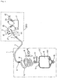
- Fig. 1 is a view schematically illustrating an embodiment of the present invention
- Fig. 2 is a view schematically illustrating a refrigerator circuit of the present invention
- Fig. 3 is a sectional view schematically illustrating a condenser utilizing gravity according to the present invention.
- reference numeral 1 denotes a coolant recovery apparatus
- 2 denotes a compressor in a vehicle from which the coolant is to be recovered
- 2A denotes a low-pressure inlet port of the compressor
- 2B denotes a high-pressure outlet port of the compressor
- 2C denotes a low-pressure hose
- 2D denotes a high-pressure hose
- 2E and 2F denote pressurized shielding portions
- 2G denotes a receiver tank
- 2H denotes an evaporator
- 2I denotes a blower
- 2J denotes a condenser
- 2K denotes an engine room
- 3 denotes a coolant recovery hose
- 4 denotes a joint with air vent
- 5 denotes a valve
- 6 denotes a piercing pipe
- 6A denotes a nut joint
- 8 and 9 denote joints
- 10 denotes a condenser utilizing gravity
- a compressor of a vehicle from which the coolant is to be recovered (or electric refrigerator, refrigerated show case, air conditioner in a large building) is driven.
- a small amount of fuel is remaining in the fuel tank of the vehicle from which to recover, or at least a small amount of fuel is remaining in the fuel pipe. Therefore, if an electric power is supplied from a DC 12V to 24V battery, the engine of the vehicle in most cases runs for 5 to 10 minutes or longer.
- the compressor 2 can be driven maintaining a considerably high reliability.
- an electric power of a 100V AC single-phase or a 200V AC three-phase may he supplied to drive the compressor.
- the vibration source 20 such as an electromagnetic vibrator or a reciprocal vibration device based on a rotary machine.
- the condenser 10 utilizing gravity is air-cooled by an electric fan 16 driven by a motor (or which may be a fan driven by the crankshaft of an engine through a V-belt).
- the condenser 10 utilizing gravity is a heat exchanger of a round or square spiral or zig-zag hose having a gravity gradient, and has a round, a square, an oval or an elliptic shape in cross section to create a small flow resistance and to exhibit a large heat-radiating effect.
- the pipe may be provided with fins to enhance the heat-radiating effect.
- the pipe may be held by plate-like fins to enhance the rigidity as a whole, so that vibration V is given to the condenser as a whole.
- the condensed droplets of freon gas in the condenser are efficiently trapped and stays in the coolant recovery tank 18 located at a lower portion due to gravity.
- the periphery of the coolant recovery tank 18 may be covered with the heat-insulating material 22 or may be cooled by the water jacket 25, so that the coolant can be contained in large amounts even in summer where the atmospheric temperature is high.
- the lower coolant take-out valve 19 is opened to transfer the coolant to another portable container.
- the coolant recovery tank 18 itself may be designed so as to be transported, as a matter of course.
- the condenser 10 utilizing gravity may be water-cooled by using the water jacket or the cooling tower which is based on the heat of vaporization of water. Or, the condenser may be of the type which is directly sprayed.
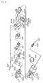
- Fig. 4 is a side view of a pipe piercing/shielding tool according to an embodiment of the present invention
- Fig. 5 is a sectional view (illustrating a portion of the front surface) along the arrow A-A in Fig. 4.
- reference numeral 50 denotes a piercing/shutting-off tool
- 51 denotes a plastic upper flange
- 52 denotes a plastic lower flange
- 53 and 54 denote arm portions
- 6 denotes a piercing pipe
- 57 denotes a disk with packing
- 60 and 70 denote coil springs
- 61 denotes a metallic upper flange
- 62 denotes a metallic lower flange
- 64A and 64B denote a first fulcrum for the upper and lower plastic flanges
- 66 denotes a second fulcrum for the upper and lower plastic flanges
- 67 denotes a first fulcrum for the upper and lower metallic flanges
- 68 denotes a second fulcrum for the upper and lower metallic flanges
- 69 denotes a lever fulcrum
- 71 denotes an upper lever
- 72 denotes a lower lever
- 73 de
- Fig. 4 illustrates a tool of the present invention modified from a known piercing pincers.
- the basic mechanism will now be briefly described.
- a pair of upper lever 71 and lower lever 72 made of a steel move via the lower flange 62.
- the upper and lower steel flanges 61 and 62 approach together to pressurize the high-pressure hose 20 (which may be a copper pipe) held therebetween, whereby the piercing tube having a sharp end pierces therethrough so that the coolant can be discharged.
- the upper plastic flange is provided with a disk 57 having an annular packaging around the central piercing pipe, preventing the coolant from escaping to the external side.
- the lower plastic flange is provided with a round groove (not shown) for clearing the end of the piercing pipe.
- a check valve 79 is provided at the outlet port of the discharge pipe.
- the stroke between the upper and lower flanges is adjusted by the screw knob 78.
- the important members are the pressure shut-off portions 2E, 2F and the arms 53, 54 supporting them, that are shown in Fig. 5 which is a front sectional view along the arrow A-A in Fig. 4.
- the arms 53, 54 are nearly symmetrically secured to the sides (left side in Fig. 5) of the upper and lower metallic flanges 61, 62.
- the piercing pipe 6 pierces into the high-pressure hose 2D which, at the same time, is tightened by the shut-off portions 2E, 2F to shut-off the flow of the coolant.
- the tool of the present invention shuts off and pierces the high-pressure hose (or copper pipe or the like pipe) simultaneously, making it possible to very highly efficiently carry out the work.
- the shut-off portions may be provided on either the right side or the left side of the upper and lower flanges. Since a strong gripping force is required, a hydraulic cylinder such as of hydraulic pressure or pneumatic pressure may be used or an electrically operated cylinder may be used to drive the tool of the present invention when the pressure cannot be applied by hand in a narrow engine room.
- Table 1 shows Examples and Comparative Examples of when the work is conducted at atmospheric temperatures of from -10°C to 30°C. The results of Table 1 will now be described.
- Fig. 6 is a graph illustrating some of the results. Ex. 1 Ex. 2 Ex. 3 Ex. 4 Ex. 5 Ext. temp.
- the condenser and the fan of the indoor evaporator are not driven in the vehicle from which to recover when the atmospheric temperature is low (about -10°C). Therefore, the indoor evaporator does not produce the endothermic action, whereby the receiver tank is frozen.
- the compressor is driven in the vehicle from which to recover or in the vehicle that is going to recover, in order to produce a negative pressure, the coolant does not flow and is not recovered.
- the coolant is not vaporized and is recovered even at -10°C.
- the coolant is once vaporized and is liquefied again. That is, the coolant is vaporized in the circuit of the vehicle from which to recover, and the circuit is frozen. Even after the passage of time of one minute and 30 seconds or so, therefore, the interior of the recovery pipe is clogged, and the gas does not flow into the vehicle that is going to recover no matter how negative pressure is applied.
- the coolant that is once vaporized must be liquefied by being pressurized by the compressor in the vehicle that is going to recover.
- the circuit is frozen and clogged due to the receiver tank that is frozen in the vehicle from which to recover. Therefore, a negative pressure is simply produced in a circuit from the frozen receiver tank to the compressor through the indoor evaporator and, hence, the coolant flows with difficulty.
- the temperature is low, therefore, an extended period of time is required for the recovery, and the recovery ratio drops as shown in Fig. 6. According to the embodiment of the present invention, however, this does not occur and the coolant is recovered very highly efficiently.
- the difference over the prior art appears conspicuously particularly at low temperatures.
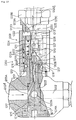
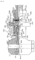
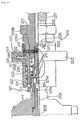
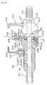
- Fig. 7 is a sectional view of an embodiment 6 (ON-OFF type) of when the fluid is to be recovered
- Fig. 8 is a sectional view of the embodiment 6 during the normal state
- Fig. 9 is a view along the arrow A-A in Fig. 8
- Fig. 10 is a view along the line B-B in Fig. 8
- Fig. 11 is a view of a socket in a disassembled state
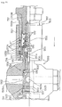
- Fig. 12 is a sectional view illustrating a portion of an embodiment 7 (proportional control type) of when the fluid is to be recovered
- Fig. 13 is a sectional view illustrating a portion of the embodiment 7 (proportional control type)
- Fig. 14 is a sectional view illustrating a portion of the socket which is part of the embodiment 7 of when the fluid is to be recovered
- Fig. 15 is a sectional view illustrating a portion of the socket of when it is normally placed (before being inserted) according to the embodiment 7
- Fig. 16 is a view along the line C-C in Fig. 15
- Fig. 17 is a sectional view illustrating a portion of the socket of the embodiment 7 of when it is being fitted
- Fig. 18 is a side view of a plug
- Fig. 19 is a view along the line D-D in Fig. 18,
- Fig. 20 is a diagram illustrating the socket unit according to the embodiment 7 in a disassembled state
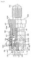
- FIG. 21 is a sectional view illustrating a portion of an embodiment 8 (depressed ON-OFF type) of when the fluid is to be recovered
- Fig. 22 is a sectional view illustrating a portion of the socket according to the embodiment 8 (normal state)
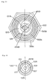
- Fig. 23 is a view along the arrow E-E in Fig. 22
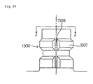
- Fig. 24 is a side view of the plug according to the embodiment 8
- Fig. 25 is a view along the line F-F in Fig. 25
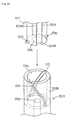
- Fig. 26 is a perspective view of a valve-depressing shaft and an upper part of the valve according to the embodiment 8
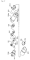
- Fig. 27 is a view of the socket according to the embodiment 8 in a disassembled state
- Fig. 28 is a sectional view illustrating a portion of an embodiment 9 (safety by-pass).
- reference numeral 1100 denotes an embodiment 6
- reference numeral 1200 denotes an embodiment 7
- reference numeral 1300 denotes an embodiment 8
- reference numeral 1400 denotes an embodiment 9
- reference numerals 1101, 1201, 1301 denote valves units (valve boxes)
- reference numerals 1102A, 1102B, 1202A, 1202B, 1302A, 1302B, 1402A and 1402B denote normal fluid passages
- reference numerals 1103, 1203, 1303 and 1403 denote valves
- reference numerals 1103A, 1203A, 1303A and 1403A denote normal passages of valves
- reference numerals 1103B, 1203B, 1303B and 1403B denote upper parts of valves
- reference numerals 1104, 1204 and 1304 denote valve-turning socket holes
- reference numerals 1104B, 1204B and 1304B denote fluid escape grooves
- reference numerals 1105, 1205 and 1305 denote fluid recovery passage
- Figs. 7 and 8 illustrate an embodiment 6, wherein a valve unit (valve box) 1101 is provided between the normal fluid passages 1102A and 1102B.
- the socket 1109 of the coupler unit is coupled to the plug 1106 and is turned from the outer side by about 90 degrees by hand or by using a tool, in order to change the passage of the fluid (e.g., gaseous/liquid coolant) flowing from the left side, and to guide it to an upper fluid recovery circuit, thereby to recover the pressurized fluid in the system.
- the fluid e.g., gaseous/liquid coolant
- the valve unit 1101 is threaded on both sides thereof as designated at 1117, 1117, and a normal fluid circuit (pipe) is connected thereto to flow the fluid from the left toward the right.
- a cylindrical cavity is formed in the valve unit 1101, and a valve 1103 is rotatably (slidably) inserted therein, the valve 1103 having the shape of a long-necked solid bottle with a thickness of an inverted T-shape in cross section.
- a threaded closure 1114 at the lower end of the valve is screwed into the threaded portion 117 via an O-ring 1110.
- Two O-rings 1110, 1110 are fitted to the lower part of the valve 1103 on the upper and lower sides of the normal fluid circuit 1102A - 1102B, and the fluid is air-/liquid-tightly maintained in the up-and-down direction.
- a normal passage 1103A is perforated at the central portion in the lower part of the valve 1103, and is usually in parallel with the normal fluid passage 1102A - 1102B in the valve box 1101 to permit the flow of the fluid without resistance (see Fig. 2).
- the normal fluid passage is shut off and, at the same time, the flow passage is changed over so that the pressurized fluid is upwardly guided through another fluid recovery inlet port 1105A perforated in the valve 1103 and that the fluid can be recovered through the fluid recovery passage 1105B.
- the upper part 1103B of the valve is a cylinder integral with the lower part of the valve rotatably (slidably) inserted in the inner cylinder in the upper part of the valve unit.
- the fluid recovery passage 1105B is upwardly extending at the central portion.
- the upper part of the valve unit 1101 is forming a plug 1106 of the coupler unit, and fits to the socket 1109 of the coupler unit that is inserted from the upper side.
- the coupler unit includes a plug 1106 (1206, 1306) and a socket 1109 (1209, 1309).
- the plug 1106 at the upper part of the valve unit 1101 has a cylindrical shape as shown in Figs. 8 and 9, and is threaded along the inner diameter at the upper end thereof as designated at 1117 so that a cap can be screwed therein, and has a slightly smaller outer diameter.
- the upper end of the valve body 1103 is on a level close to the lower end of the threaded portion 1117.
- the fluid recovery passage at the center having a diameter slightly larger than the inner diameter of the fluid recovery passage is exposed as a valve-turning socket hole 1104 which is a square hole as viewed on a plan view.
- valve-turning socket hole 1104 and the lower end 1111A of the coupling shaft 1111 inserted therein has a relationship of lock and key, and the opposite relationship is also allowable (see claim 1).
- the check valve 1119 in the socket shown in Figs. 7 and 8 is urged by the valve coil spring 1112 so as to push down the upper end of the plug located on the lower side.
- O-rings 1110, 1110 and 1110 are so arranged that air-tightness/liquid-tightness is maintained between the outer periphery of the upper end of the plug and the coupling shaft 1111.
- the check valve 1119 works to prevent the leakage of the fluid in the fluid recovery circuit 1105C to the external side when the socket 1109 is separated away from the plug 1106 (see Fig. 8). At this moment, the gap between the check valve 1119 and the coupling shaft 1111 is closed by the two O-rings 1110, 1110. When the socket 1109 is pushed onto the plug 1106, the check valve 1119 rises against the urging force of the valve coil spring 1112, and the fluid recovery circuit 1105B in the valve is communicated with the fluid recovery circuit 1105C in the socket (see Fig. 7).
- the upper end of the coupling shaft 1111 is threaded as designated at 1117 and meshes with the inner threaded portion 1117 of the socket inner 1109.
- the socket inner 1109B is in mesh at its another outer threaded portion 1117 with the inner diameter of the socket outer 1109A.
- the upper end of the socket outer 1109A is connected to the fluid recovery passage that is threaded along its outer periphery as designated at 1117.
- a strong adhesive is applied to the threaded junction portion between the coupling shaft 1111 and the socket inner 1109 and between the socket inner 1109B and the socket outer 1109A prior to joining them together.
- the threaded portion when it is a right-handed screw is particularly strongly secured when the socket is turned clockwise as the thrust of the shoulder ends comes into a halt.
- the junction portion is strongly secured due to the frictional force of the threaded portions and the adhering force of the adhesive.
- the positioning protuberance 1140 on the inner surface of the socket 1109 is fitted along the L-shaped positioning groove 1140A in the outer surface of the plug 1106 shown in Figs. 9 and 10. That is, the socket 1109 is once pushed down against the urging force of the valve coil spring 1112 so that the lower end 1111A of the coupling shaft is fitted into the valve-turning socket hole 1104 of the upper part 1103B of the valve, and the socket 1109 is turned by about 90 degrees (desirably from about 45 to about 90 degrees) so that the valve 1103 is turned so as to be shifted from the state shown in Fig. 8 to the state shown in Fig. 7.
- the positioning protuberance 1140 is anchored at the end of the L-shaped positioning groove that is slightly recessed upward being urged by the valve coil spring 1112.
- the L-shaped grooves may be formed in a plural number in the outer periphery of the plug maintaining a distance of 120 degrees to 180 degrees to accomplish improved anchored state of the socket and to decrease the leakage.
- the normal fluid passage 1102A - 1102B is closed, and the fluid flowing from the left side goes up through the fluid recovery circuit inlet port 1105A and the fluid recovery circuit 1105B.
- the fluid then passes through the pair of fluid escape grooves 104B formed in the lower end 111A of the coupling shaft inserted in the valve-turning socket hole as described earlier, and flows upward to the upper end of the socket.
- the ON and OFF are changed over, and no consideration has been given to the intermediate proportional control. That is, the normal fluid passage is fully opened/fully closed, and the fluid recovery circuit is fully closed/fully opened corresponding thereto.
- valve-turning socket 1104 and the lower end 1111A of the coupling shaft fitted thereto clearly shown in Figs. 9 and 10 may have such shapes as to transmit the torque and may be equipped with the fluid escape grooves 1104B. Therefore, they are not limited to square shapes shown in the plan view of Fig. 4, but may have a figure with spline, a polygonal shape such as pentagon or hexagon, or may have an elliptic shape.
- Fig. 11 is a view illustrating the socket of the embodiment 6 in a disassembled state, from which the structure of the embodiment 6 can be easily understood.
- An embodiment 7 has a basic structure that resembles the embodiment 6, but is of the proportional control type which is different from the ON-OFF type of the embodiment 6. As shown in Figs. 12 to 15, the proportional control is executed via a coupling pin 1213 which couples the coupling shaft 1211 which is the innermost core to the sleeve grip 1223 of the outermost circumference in the radial direction.
- the sleeve grip 1223 is twisted to turn the sleeve 1222.
- the coupling pin 1213 rotates in the circumferential direction in the holes 1213B and 1213C which are elongated in the circumferential direction of the socket outer 1209A, and the coupling shaft 1211 which is the inner core is turned by the same angle (see Figs. 15 and 20).
- the inner surface at the upper part of the sleeve 1222 is vertically splined, and is contacted to the outer end of the coupling pin 1213 to slide up and down and to transmit torque thereto.
- the coupling shaft 1211 can be turned by the turn of the sleeve irrespective of the motion of the sleeve 1222 in the up-and-down direction.
- the socket 1209 has a sleeve 1222 on the outer side and is equipped with a locking ball-fitted connector having a plurality of locking balls 1216 at the lower portion.
- the plug of the opposing side has an annular engaging protuberance 1207 and a positioning notch 1208.
- the positioning protuberance 1218 on the inner diameter of the socket outer 1209A must be pushed down along the positioning notch 1208 of the plug.
- the sleeve 1222 is limited by the downwardly urging coil spring 1212A, by the rod-like positioning protuberance 1220 and by the stop ring 1215 fitted to the annular groove 1215A at the lower end of the socket outer 1209A.
- the sleeve 1222 is allowed to be raised only when the rod-like positioning protuberance 1220 is fitted to the positioning recessed portion 1221 by turning the sleeve 1222.
- the fluid usually flows straight from the left side toward the right side.
- the valve 1208 is turned by a maximum of about 90 degrees, whereby the normal fluid circuit 1202 is closed as shown in Fig. 12, the fluid recovery circuit 1205A is opened, and the fluid all flows into the upper fluid recovery circuit 1205 and is recovered by a separate tank.
- the opening degree of the fluid recovery circuit inlet port 1205A can be adjusted depending upon the rotational angle of the sleeve 1222.
- both the inlet port 1203A of the normal fluid circuit in the valve 1203 and the inlet port 1205A of the fluid recovery circuit can be exposed to the normal fluid passage side 1202A at an intermediate angle (e.g., valve rotational angle of about 45 degrees).
- the valve 1203 is necessarily in parallel with the normal fluid circuit 1202 due to the above-mentioned constitution, and the fluid is not undesirably discharged out of the system.
- the coil springs 122B and the balls 1227 inserted in the pair of grips 1223 and 1223 constitute a so-called click-stop mechanism like a manual F-stop mechanism of a camera in relation to recessed portions formed in the outer circumference of the socket outer 1209A, that is not shown, making it possible to easily select any valve opening degree, such as fluid recovery circuit 0 (fully closed), 1/4, 1/2, 3/4, 1 (fully opened).
- An embodiment 8 mechanically resembles the embodiment 7 and copes with such a situation where it is difficult, due to the circuit structure, to turn the socket of the coupler unit for recovering the fluid.
- the valve is turned by only pushing and pulling the socket by using a spiral groove and a protuberance that engages with the spiral groove.
- the embodiment 8 is based on the ON-OFF control like the embodiment 6. In the embodiments 6 and 8, however, the proportional control can be easily accomplished relying on the combination with a screw mechanism. This, however, is not so much meaningful since the embodiment 8 tends to become complex.
- valve 1303 is turned by pushing and pulling the socket 1309.
- a thrust bearing such as a needle roller bearing between the lower part of the valve an the upper surface 1303S of the threaded closure 1314 and/or between the shoulder portion of the valve and the valve box 1303T.
- a pair of protuberances 1330 and 1330 are attached to the outer periphery of the lower end 1311A of the coupling shaft that moves up and down along the spline but does not rotate. These protuberances 1330 and 1330 are engaged with a pair of spiral grooves 1331 and 1331 formed in the surface of the cylindrical upper part 1303B of the valve, the valve 1303 is turned via the coupling shaft 1311 upon moving the socket 1309 up and down by hand, in order to accomplish the function of the three-way valve similar to those of the embodiments 6, 7 and 8 (see Figs. 26 and 27).
- reference numeral 1318 denotes a protuberance inwardly protruded in the socket, which engages with the notch 1308 of the side of the plug of Fig. 24 so as to secure the socket.
- Other respects are the same as those of the embodiments 6, 7 and 8.
- Fig. 28 is a sectional view illustrating a portion of an embodiment 9.
- the three-way valve 1401 itself may be the one used in the embodiments 6, 7 and 8 or may be any other one.
- a safety measure is taken in case the three-way valve does not work to a sufficient degree. That is, the fluid flows through the normal fluid circuit 1402A - 1402B.
- the valve 1442A downwardly pushed by the valve spring 1412 in the safety valve 1442 is opened when the pressure reaches a dangerous level, so that the pressurized fluid is released into the normal fluid circuit 402B on the outlet side through a by-pass 1443.
- the power source circuit for the compressor in the refrigerator circuit is broken by a pressure switch 1441 through a relay circuit.
- the operation pressure A of the safety valve 1442 and the operation pressure B of the pressure switch 1441 are usually set to be B ⁇ A. This is because a predetermined time constant is required for halting the compressor. It is desired to provide both the safety valve 1442 and the pressure switch 1441. However, either one of them may often suffice for the need provided the sensitivity and time constant are designed well.
- the fuel remaining in the fuel tank of the vehicle from which the coolant is to be recovered is burned as efficiently as possible to enhance safety after the recovery and to lessen contamination to the environment.
- a three-way valve for recovering a pressurized fluid comprising a valve unit and a coupler unit, and having a function for opening the three-way valve unit to the recovery circuit simultaneously with the connection of the coupler unit to the recovery circuit.
- the pressure does not suddenly increase despite the compressor is not readily halted, and the pressurized fluid is safely recovered through the recovery circuit out of the system.
Applications Claiming Priority (4)
| Application Number | Priority Date | Filing Date | Title |
|---|---|---|---|
| JP2039698 | 1998-01-17 | ||
| JP02039698A JP3345577B2 (ja) | 1998-01-17 | 1998-01-17 | 冷媒回収法およびそのための装置と工具 |
| JP10377453A JP3106430B2 (ja) | 1998-12-31 | 1998-12-31 | 加圧流体回収用三方弁 |
| JP37745398 | 1998-12-31 |
Publications (2)
| Publication Number | Publication Date |
|---|---|
| EP0931992A2 true EP0931992A2 (fr) | 1999-07-28 |
| EP0931992A3 EP0931992A3 (fr) | 2005-03-30 |
Family
ID=26357341
Family Applications (1)
| Application Number | Title | Priority Date | Filing Date |
|---|---|---|---|
| EP99100743A Withdrawn EP0931992A3 (fr) | 1998-01-17 | 1999-01-16 | Procédé de récupération de frigorigène, appareil associé, outil associé et valve à trois voies pour la récupération d'un fluide sous pression |
Country Status (5)
| Country | Link |
|---|---|
| US (1) | US6216473B1 (fr) |
| EP (1) | EP0931992A3 (fr) |
| KR (1) | KR19990067961A (fr) |
| AU (1) | AU1211799A (fr) |
| CA (1) | CA2259051A1 (fr) |
Cited By (1)
| Publication number | Priority date | Publication date | Assignee | Title |
|---|---|---|---|---|
| CN114111127A (zh) * | 2020-08-26 | 2022-03-01 | 广东美的暖通设备有限公司 | 换热器、电控盒及空调系统 |
Families Citing this family (8)
| Publication number | Priority date | Publication date | Assignee | Title |
|---|---|---|---|---|
| US6446453B1 (en) * | 2000-10-12 | 2002-09-10 | Interdynamics, Inc. | Unitary hose connector for automobile air conditioner servicing and kit utilizing same |
| US6463359B2 (en) * | 2001-02-20 | 2002-10-08 | Infotech Ag | Micro-alignment pick-up head |
| US7051996B2 (en) * | 2003-11-19 | 2006-05-30 | Parker-Hannifin Corporation | Plug-style air-conditioning service valve |
| US7516942B2 (en) * | 2003-11-19 | 2009-04-14 | Parker-Hannifin Corporation | Plug-style air-conditioning service valve |
| US8297063B2 (en) * | 2008-08-12 | 2012-10-30 | General Electric Company | Method for servicing a refrigeration system |
| CN109690220B (zh) | 2016-09-09 | 2020-06-09 | 株式会社电装 | 设备温度调节装置的制造方法以及工作流体的填充方法 |
| GB2586482B (en) * | 2019-08-20 | 2022-08-17 | Singh Bath Charanjit | Modified ball valve |
| CN114623380A (zh) * | 2022-03-23 | 2022-06-14 | 新智认知数据服务有限公司 | Lng场站火雾识别系统 |
Citations (1)
| Publication number | Priority date | Publication date | Assignee | Title |
|---|---|---|---|---|
| JPH0968292A (ja) | 1995-08-29 | 1997-03-11 | Joban Debero Enjinia Kk | 連結及び自動スリーブロック機構型カップラー |
Family Cites Families (14)
| Publication number | Priority date | Publication date | Assignee | Title |
|---|---|---|---|---|
| US4998413A (en) * | 1988-09-01 | 1991-03-12 | Nippondenso Co., Ltd. | Refrigerant recovery system |
| DE3830718A1 (de) * | 1988-09-09 | 1990-03-22 | Licentia Gmbh | Verfahren und vorrichtung zur entsorgung eines kaeltemittelkreislaufs |
| US5094277A (en) * | 1989-06-27 | 1992-03-10 | Ashland Oil Inc. | Direct condensation refrigerant recovery and restoration system |
| US4996848A (en) * | 1989-09-28 | 1991-03-05 | Whirlpool Corporation | Method and apparatus for recovering refrigerants from home refrigeration systems |
| US5027605A (en) * | 1990-05-17 | 1991-07-02 | Murray Corporation | Oil injection system for air conditioning equipment |
| US5220810A (en) * | 1990-09-26 | 1993-06-22 | Technical Chemical Company | Refrigerant recovery system with flush mode and associated flushing adapter apparatus |
| US5214927A (en) * | 1990-10-05 | 1993-06-01 | Squires David C | Method and apparatus for passive refrigerant and storage |
| JPH062995A (ja) | 1992-06-18 | 1994-01-11 | Nakajima Jidosha Denso:Kk | フロンガスの回収方法及び回収装置 |
| US5275013A (en) * | 1992-09-24 | 1994-01-04 | Price Leslie D | Reusable tube piercing tool for refrigerant recovery |
| JPH06241621A (ja) * | 1993-02-15 | 1994-09-02 | Mitsui Touatsu Liquid Kaabonitsuku Kk | フロンガス回収装置 |
| US5699678A (en) * | 1996-04-17 | 1997-12-23 | Trigiani; Phil | Charging device |
| JPH09292169A (ja) * | 1996-04-26 | 1997-11-11 | Seiko Seiki Co Ltd | 空気調和装置 |
| US5645104A (en) * | 1996-10-07 | 1997-07-08 | Baumgartner; A. C. | Line evacuation device |
| US5915402A (en) * | 1998-09-21 | 1999-06-29 | Mitchell, Ii; William G. | Refrigeration isolation valve apparatus and method of use |
-
1999
- 1999-01-13 US US09/229,325 patent/US6216473B1/en not_active Expired - Fee Related
- 1999-01-15 AU AU12117/99A patent/AU1211799A/en not_active Abandoned
- 1999-01-15 CA CA002259051A patent/CA2259051A1/fr not_active Abandoned
- 1999-01-16 EP EP99100743A patent/EP0931992A3/fr not_active Withdrawn
- 1999-01-18 KR KR1019990001341A patent/KR19990067961A/ko not_active Application Discontinuation
Patent Citations (1)
| Publication number | Priority date | Publication date | Assignee | Title |
|---|---|---|---|---|
| JPH0968292A (ja) | 1995-08-29 | 1997-03-11 | Joban Debero Enjinia Kk | 連結及び自動スリーブロック機構型カップラー |
Cited By (1)
| Publication number | Priority date | Publication date | Assignee | Title |
|---|---|---|---|---|
| CN114111127A (zh) * | 2020-08-26 | 2022-03-01 | 广东美的暖通设备有限公司 | 换热器、电控盒及空调系统 |
Also Published As
| Publication number | Publication date |
|---|---|
| AU1211799A (en) | 1999-08-05 |
| US6216473B1 (en) | 2001-04-17 |
| CA2259051A1 (fr) | 1999-07-17 |
| EP0931992A3 (fr) | 2005-03-30 |
| KR19990067961A (ko) | 1999-08-25 |
Similar Documents
| Publication | Publication Date | Title |
|---|---|---|
| EP0931992A2 (fr) | Procédé de récupération de frigorigène, appareil associé, outil associé et valve à trois voies pour la récupération d'un fluide sous pression | |
| US10359220B2 (en) | Systems, methods and apparatus for servicing a refrigeration system | |
| US7147004B1 (en) | Check valve for cam lock fitting | |
| US10288333B2 (en) | Refrigeration charging devices and methods of use thereof | |
| US11060774B2 (en) | Apparatus and methodology for opening refrigerant sources while servicing automotive refrigeration systems | |
| EP2933584A1 (fr) | Circuit de fluide frigorigène | |
| US20070113575A1 (en) | Valve manifold assembly | |
| US10113657B2 (en) | Multiple valve refrigerant leak protection device | |
| US20180313451A1 (en) | Multi-ported refrigeration valve assembly | |
| US5431189A (en) | Flow control manifold and gauge | |
| EP0623203A4 (fr) | Systeme de vannes a collecteur de derivation pour charger, preparer et/ou tester des systemes refrigerants. | |
| WO1994012835A1 (fr) | Systeme de vannes a collecteur de derivation pour charger, preparer et/ou tester des systemes refrigerants | |
| US8225618B2 (en) | Refrigerant recovery method and apparatus | |
| US6837064B2 (en) | Coupling for servicing a pressurized system | |
| US3717008A (en) | Charging valve tool | |
| US11713910B2 (en) | Environmental air conditioning and refrigeration isolation safety valve | |
| JP3380715B2 (ja) | 熱交換装置の処理方法 | |
| US5551247A (en) | Refrigerant handling system and method especially for flammable and potentially flammable refrigerants | |
| KR20060037052A (ko) | 팬을 구비한 수액기와, 그 수액기를 포함한 냉난방 공조장치 | |
| JP3001696U (ja) | フロン回収装置 | |
| Equipment | Air Conditioning | |
| EP3631324A1 (fr) | Pompe de réfrigérant à service intégrée | |
| WO1994018511A1 (fr) | Dispositif de recuperation de chlorofluorocarbone | |
| JPH07218102A (ja) | コンテナ用冷凍ユニットの換気装置 | |
| MXPA99008677A (es) | Valvula de bola de colocacion incremental |
Legal Events
| Date | Code | Title | Description |
|---|---|---|---|
| PUAI | Public reference made under article 153(3) epc to a published international application that has entered the european phase |
Free format text: ORIGINAL CODE: 0009012 |
|
| AK | Designated contracting states |
Kind code of ref document: A2 Designated state(s): AT BE CH CY DE DK ES FI FR GB GR IE IT LI LU MC NL PT SE |
|
| AX | Request for extension of the european patent |
Free format text: AL;LT;LV;MK;RO;SI |
|
| PUAL | Search report despatched |
Free format text: ORIGINAL CODE: 0009013 |
|
| AK | Designated contracting states |
Kind code of ref document: A3 Designated state(s): AT BE CH CY DE DK ES FI FR GB GR IE IT LI LU MC NL PT SE |
|
| AX | Request for extension of the european patent |
Extension state: AL LT LV MK RO SI |
|
| 17P | Request for examination filed |
Effective date: 20050929 |
|
| AKX | Designation fees paid |
Designated state(s): AT BE CH CY DE DK ES LI |
|
| STAA | Information on the status of an ep patent application or granted ep patent |
Free format text: STATUS: THE APPLICATION IS DEEMED TO BE WITHDRAWN |
|
| 18D | Application deemed to be withdrawn |
Effective date: 20060703 |