EP0931442A1 - Epandeur d'engrais - Google Patents
Epandeur d'engrais Download PDFInfo
- Publication number
- EP0931442A1 EP0931442A1 EP99200059A EP99200059A EP0931442A1 EP 0931442 A1 EP0931442 A1 EP 0931442A1 EP 99200059 A EP99200059 A EP 99200059A EP 99200059 A EP99200059 A EP 99200059A EP 0931442 A1 EP0931442 A1 EP 0931442A1
- Authority
- EP
- European Patent Office
- Prior art keywords
- hub
- stirring
- container
- fertilizer spreader
- fertilizer
- Prior art date
- Legal status (The legal status is an assumption and is not a legal conclusion. Google has not performed a legal analysis and makes no representation as to the accuracy of the status listed.)
- Withdrawn
Links
- 239000003337 fertilizer Substances 0.000 title claims abstract description 60
- 238000003756 stirring Methods 0.000 claims abstract description 60
- 230000015572 biosynthetic process Effects 0.000 description 1
- 238000010276 construction Methods 0.000 description 1
- 230000007423 decrease Effects 0.000 description 1
- 230000003247 decreasing effect Effects 0.000 description 1
- 230000000694 effects Effects 0.000 description 1
- 210000003608 fece Anatomy 0.000 description 1
- 239000010871 livestock manure Substances 0.000 description 1
- 238000007789 sealing Methods 0.000 description 1
- 239000007787 solid Substances 0.000 description 1
Images


Classifications
-
- A—HUMAN NECESSITIES
- A01—AGRICULTURE; FORESTRY; ANIMAL HUSBANDRY; HUNTING; TRAPPING; FISHING
- A01C—PLANTING; SOWING; FERTILISING
- A01C15/00—Fertiliser distributors
- A01C15/005—Undercarriages, tanks, hoppers, stirrers specially adapted for seeders or fertiliser distributors
- A01C15/006—Hoppers
- A01C15/007—Hoppers with agitators in the hopper
Definitions
- the invention relates to a fertilizer spreader provided with a substantially funnel-shaped container comprising a bottom and at least one outlet opening present therein, with a spreading element disposed under said outlet opening and with a stirring unit disposed in said container, which stirring unit is provided with a hub comprising a plurality of projecting stirring fingers, which hub is freely rotatable about a first shaft which is eccentrically, non-rotatably fixed on a second shaft, which can be rotatably driven.
- a fertilizer spreader of this type is known, for example from DE-A-36 37 045.
- a hood is mounted above the stirring unit in the funnel-shaped container, which hood functions to prevent fertilizer present in the container from exerting pressure on the fertilizer which is present at the location of the stirring unit.
- the stirring unit there may be a problem of the stirring unit damaging the manure, especially when no fertilizer is being delivered via the outlet opening for a short period, as a result of which so much heat is generated that a solid mass of fertilizer is formed, which interferes with the outflow of the fertilizer, possibly even preventing said outflow altogether.
- the objective of the invention is to provide a fertilizer spreader of the kind referred to in the introduction, wherein this drawback has been overcome in a simple yet efficient manner.
- the fertilizer spreader according to the invention is characterized in that the operating area of the stirring unit is located at some distance above the bottom in a funnel-shaped flaring part of the container.
- the invention is based on the insight that it is not necessary to position the operating area of the stirring unit as closely to the outlet opening as possible in order to achieve a satisfactory delivery of the fertilizer via the outflow opening.
- the stirring unit Since the stirring unit is operative in an area some distance above the bottom, the fertilizer can be loosened more easily by the stirring fingers at this location, and the operation of the stirring unit will cause any damaged fertilizer to sink into the layer of fertilizer that is present between the stirring unit and the bottom, so that no coagulated mass of fertilizer will be formed at the location of the operating area of the stirring unit.
- the hub is positioned some distance above the bottom, and the stirring fingers extend from the hub into the container in a direction away from the bottom.
- Fig. 1 is a schematic sectional view/side view of a part of an embodiment of the fertilizer spreader according to the invention.
- Fig. 2 is a plan view of the bottom part of the fertilizer spreader of Fig. 1.
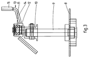
- Fig. 3 is a side view of the spreading element and of the stirring unit of the fertilizer spreader of Fig. 1.
- Fig. 1 shows a part of a fertilizer spreader, which is provided with a substantially funnel-shaped container 1, which is shown only partially.
- Container 1 comprises a fixed bottom plate 2, in which three circular outlet openings 3 (see Fig. 2) are present.
- Bottom plate 2 supports a cylinder 4, whose bottom 3 is provided with profiled openings 5, which can be aligned with outlet openings 3 by rotating cylinder 4 to a greater or lesser extent so as to adjust the metering by the fertilizer spreader.
- cylinder 4 comprises an outwardly extending end edge 6 at its upper side, which surrounds the open underside 7 of container 1.
- the opening between end edge 7 and the outer wall of container 1 is closed by a rubber sealing ring, which is not shown in the drawing.
- the fertilizer spreader is provided with an intermediate plate 8 as shown in Fig. 3, under which a spreading element can be mounted, possibly via an extended shaft. Intermediate plate 8 can be rotated via a shaft 9, in a manner known per se, at a variable speed in dependence on the desired spreading range.
- a shaft 11 is fixed eccentrically on the end of shaft 9 that extends upwards into cylinder 4 by means of a mounting bush 10.
- a hub 12 is mounted on shaft 11 in such a manner that it can rotate freely by means of a schematically indicated ball bearing.
- Hub 12 is provided with four stirring fingers 13, which are each hook-shaped and which comprise a first part 14, which slopes upwards from hub 12 in a direction away from bottom plate 2, and a second part 15 contiguous thereto, which extends substantially axially, i.e.
- Said axial parts 15 comprise an end portion of triangular cross-section, one surface of which extends obliquely to the radial direction.
- Hub 12 and stirring fingers 13 together provide a stirring unit, by means of which the fertilizer in container 1 is loosened, so that an even outflow of fertilizer via outlet openings 3 to intermediate plate 8 is ensured.
- Said stirring unit 12, 13 is driven by the drive gear of shaft 9 (not shown). Since shaft 11 is disposed eccentrically with respect to shaft 9, hub 12 will move in a circular path. Due to the mounting of the hub 12 on the shaft 11 in a freely rotatable manner, the hub 12 can be stationary with respect to this shaft, so that the hub 12 with the stirring fingers 13 does not rotate.
- the stirring fingers 13 When the container 1 is filled with fertilizer, the stirring fingers 13 are pressed into the fertilizer by the eccentric movement of hub 12, and hub 12 is caused to rotate about shaft 11 as a result of the presence of the oblique surfaces on the end portions of the stirring fingers 13.
- the number of revolutions of stirring unit 12, 13 is much smaller than the number of revolutions of intermediate plate 8 and shaft 9, respectively.
- the number of revolutions of shaft 9 can vary from 540 upto 950 depending on the type of fertilizer spreader, wherein the number of revolutions of the stirring unit 12, 13 will vary from about 30 upto 80.
- the operating area of the stirring unit 12, 13 is located some distance above the bottom plate 2 in an area of the container 1 which flares outwardly like a funnel. This is obtained in the described fertilizer in that hub 12 is located some distance above the bottom plate 2 which has the same order of magnitude as the length of the axial parts 15 of the stirring fingers 13.
- the hub 12 is located substantially at the height of the end edge 7 of the container 1. Thereby, the operating area does not extend further in height direction as necessary for loosening the fertilizer streaming towards.
- the axial parts 15 are provided with a surface oblique to the radial direction only and the side of the axial parts 15 leading in rotational direction is rounded, so that the stirring unit 12,13 when rotating meets less resistance from the fertilizer.
- the operating area of stirring unit 12, 13 is located some distance above bottom plate 2, to wit in an area of the container which is funnel-shaped and flaring. This minimizes the amount of damage which is done to the fertilizer by stirring fingers 13 and hub 12.
- the stirring fingers 13 can be pressed into the fertilizer relatively easily, since the fertilizer can move out into the upwardly diverging container.
- a layer of fertilizer will be present under the operating area of stirring unit 12, 13 at all times, into which any fertilizer that has been pulverized by the operation of the stirring unit can sink, so that there will be no formation of a coagulated fertilizer mass in said operating area.
- a proper flow of fertilizer will be started at all times when the outlet openings 3 are opened.
- stirring unit 12, 13 is furthermore provided with an additional stirring finger 17, which extends obliquely towards bottom plate 2 from hub 12.
- Said additional stirring finger 17 acts to keep the fertilizer in loosened condition in the area below the operating area 16 of stirring unit 12, 13.
- additional stirring finger 17 is shown, it is also possible to provide two or more stirring fingers 17, if desired.
- the spacing between the central axis of shaft 9 and that of shaft 11 varies from 6-12 mm and is preferably at least approximately 9 mm. Tests have shown that a satisfactory stirring action is achieved by using the aforementioned spacing at the usual rotational speeds of intermediate plate 8, whilst minimizing the amount of damage to the fertilizer.
Landscapes
- Life Sciences & Earth Sciences (AREA)
- Soil Sciences (AREA)
- Environmental Sciences (AREA)
- Fertilizing (AREA)
Applications Claiming Priority (2)
| Application Number | Priority Date | Filing Date | Title |
|---|---|---|---|
| NL1008034A NL1008034C2 (nl) | 1998-01-15 | 1998-01-15 | Kunstmeststrooier. |
| NL1008034 | 1998-01-15 |
Publications (1)
| Publication Number | Publication Date |
|---|---|
| EP0931442A1 true EP0931442A1 (fr) | 1999-07-28 |
Family
ID=19766350
Family Applications (1)
| Application Number | Title | Priority Date | Filing Date |
|---|---|---|---|
| EP99200059A Withdrawn EP0931442A1 (fr) | 1998-01-15 | 1999-01-12 | Epandeur d'engrais |
Country Status (2)
| Country | Link |
|---|---|
| EP (1) | EP0931442A1 (fr) |
| NL (1) | NL1008034C2 (fr) |
Cited By (2)
| Publication number | Priority date | Publication date | Assignee | Title |
|---|---|---|---|---|
| EP1656822A1 (fr) * | 2004-11-12 | 2006-05-17 | Harry Sörensen | Distributeur et méthode pour la distribution de substances liquides telles que du lisier aux sorties d'un épandeur de lisier |
| DK201400478A1 (da) * | 2014-08-28 | 2016-03-07 | Harry Højvang Sørensen | Smøresystem til gyllefordeler med excentrisk arbejdende skæreringe. |
Citations (4)
| Publication number | Priority date | Publication date | Assignee | Title |
|---|---|---|---|---|
| DE1278780B (de) * | 1964-01-25 | 1968-09-26 | Amazonen Werke Dreyer H | Ruehrwerk fuer Zentrifugalstreuer, insbesondere zum Ausstreuen von mineralischen Duengemitteln |
| DE1407677A1 (de) * | 1958-02-03 | 1968-10-31 | Lely Nv C Van Der | Streugeraet,vorzugsweise Kunstduengerstreuer |
| DE3637045A1 (de) | 1985-11-01 | 1987-05-07 | Laursen As A P | Ruehrwerk fuer einen duengerstreuer |
| EP0813806A1 (fr) * | 1996-06-13 | 1997-12-29 | A.P. Laursen A/S | Arrangement pour remuer une substance granulaire, en particulier fertilisateur, dans la sortie d'un conteneur |
-
1998
- 1998-01-15 NL NL1008034A patent/NL1008034C2/nl not_active IP Right Cessation
-
1999
- 1999-01-12 EP EP99200059A patent/EP0931442A1/fr not_active Withdrawn
Patent Citations (4)
| Publication number | Priority date | Publication date | Assignee | Title |
|---|---|---|---|---|
| DE1407677A1 (de) * | 1958-02-03 | 1968-10-31 | Lely Nv C Van Der | Streugeraet,vorzugsweise Kunstduengerstreuer |
| DE1278780B (de) * | 1964-01-25 | 1968-09-26 | Amazonen Werke Dreyer H | Ruehrwerk fuer Zentrifugalstreuer, insbesondere zum Ausstreuen von mineralischen Duengemitteln |
| DE3637045A1 (de) | 1985-11-01 | 1987-05-07 | Laursen As A P | Ruehrwerk fuer einen duengerstreuer |
| EP0813806A1 (fr) * | 1996-06-13 | 1997-12-29 | A.P. Laursen A/S | Arrangement pour remuer une substance granulaire, en particulier fertilisateur, dans la sortie d'un conteneur |
Cited By (3)
| Publication number | Priority date | Publication date | Assignee | Title |
|---|---|---|---|---|
| EP1656822A1 (fr) * | 2004-11-12 | 2006-05-17 | Harry Sörensen | Distributeur et méthode pour la distribution de substances liquides telles que du lisier aux sorties d'un épandeur de lisier |
| DK201400478A1 (da) * | 2014-08-28 | 2016-03-07 | Harry Højvang Sørensen | Smøresystem til gyllefordeler med excentrisk arbejdende skæreringe. |
| DK178936B1 (da) * | 2014-08-28 | 2017-06-12 | Harry Højvang Sørensen | Gyllefordeler |
Also Published As
| Publication number | Publication date |
|---|---|
| NL1008034C2 (nl) | 1999-07-16 |
Similar Documents
| Publication | Publication Date | Title |
|---|---|---|
| US4166581A (en) | Spreader for particulate material | |
| US7261248B2 (en) | Spray nozzle | |
| EP0931442A1 (fr) | Epandeur d'engrais | |
| KR20030089423A (ko) | 분립체 공급기 | |
| GB2251166A (en) | Slurry spreaders | |
| CA1224824A (fr) | Epandeur mecanique de granules | |
| US4126250A (en) | Apparatus for dispensing granular material | |
| US4776519A (en) | Device for spreading granular and/or powdery material | |
| US4106707A (en) | Feed distributor for gyratory crusher | |
| US3863815A (en) | Grain metering device | |
| US5447404A (en) | Silo discharge arrangement | |
| JPH08268558A (ja) | 粉粒体圧送用テーブルフィーダ | |
| CN114982444A (zh) | 一种肥料抛撒式施肥机 | |
| JPS6338739Y2 (fr) | ||
| EP0078585B1 (fr) | Dispositif de distribution de produits granuleux et/ou poudreux | |
| WO1991005460A1 (fr) | Appareil de decharge | |
| JPS6115729B2 (fr) | ||
| RU2269245C2 (ru) | Способ использования центробежного разбрасывателя для распределения удобрений (варианты) | |
| JPH089007B2 (ja) | 精米機の付着糠防止装置 | |
| KR200315259Y1 (ko) | 비료 살포 장치 | |
| WO2005033417A1 (fr) | Systeme d'epandage pour engin de voirie et engin de voirie comprenant un systeme d'epandage | |
| EP0813806A1 (fr) | Arrangement pour remuer une substance granulaire, en particulier fertilisateur, dans la sortie d'un conteneur | |
| JP2829125B2 (ja) | 連続ミキサー | |
| JPH054867U (ja) | 自動給餌機 | |
| SU1404011A1 (ru) | Лункопрессова се лка |
Legal Events
| Date | Code | Title | Description |
|---|---|---|---|
| PUAI | Public reference made under article 153(3) epc to a published international application that has entered the european phase |
Free format text: ORIGINAL CODE: 0009012 |
|
| AK | Designated contracting states |
Kind code of ref document: A1 Designated state(s): AT BE CH CY DE DK ES FI FR GB GR IE IT LI LU MC NL PT SE |
|
| AX | Request for extension of the european patent |
Free format text: AL;LT;LV;MK;RO;SI |
|
| AKX | Designation fees paid | ||
| REG | Reference to a national code |
Ref country code: DE Ref legal event code: 8566 |
|
| STAA | Information on the status of an ep patent application or granted ep patent |
Free format text: STATUS: THE APPLICATION IS DEEMED TO BE WITHDRAWN |
|
| 18D | Application deemed to be withdrawn |
Effective date: 20000129 |