EP0930980B1 - Traction device for vehicle wheels - Google Patents
Traction device for vehicle wheels Download PDFInfo
- Publication number
- EP0930980B1 EP0930980B1 EP97911939A EP97911939A EP0930980B1 EP 0930980 B1 EP0930980 B1 EP 0930980B1 EP 97911939 A EP97911939 A EP 97911939A EP 97911939 A EP97911939 A EP 97911939A EP 0930980 B1 EP0930980 B1 EP 0930980B1
- Authority
- EP
- European Patent Office
- Prior art keywords
- tread
- road surface
- segments
- tire
- chamber
- Prior art date
- Legal status (The legal status is an assumption and is not a legal conclusion. Google has not performed a legal analysis and makes no representation as to the accuracy of the status listed.)
- Expired - Lifetime
Links
Images


Classifications
-
- B—PERFORMING OPERATIONS; TRANSPORTING
- B60—VEHICLES IN GENERAL
- B60C—VEHICLE TYRES; TYRE INFLATION; TYRE CHANGING; CONNECTING VALVES TO INFLATABLE ELASTIC BODIES IN GENERAL; DEVICES OR ARRANGEMENTS RELATED TO TYRES
- B60C11/00—Tyre tread bands; Tread patterns; Anti-skid inserts
-
- B—PERFORMING OPERATIONS; TRANSPORTING
- B60—VEHICLES IN GENERAL
- B60B—VEHICLE WHEELS; CASTORS; AXLES FOR WHEELS OR CASTORS; INCREASING WHEEL ADHESION
- B60B11/00—Units comprising multiple wheels arranged side by side; Wheels having more than one rim or capable of carrying more than one tyre
- B60B11/02—Units of separate wheels mounted for independent or coupled rotation
-
- B—PERFORMING OPERATIONS; TRANSPORTING
- B60—VEHICLES IN GENERAL
- B60B—VEHICLE WHEELS; CASTORS; AXLES FOR WHEELS OR CASTORS; INCREASING WHEEL ADHESION
- B60B15/00—Wheels or wheel attachments designed for increasing traction
- B60B15/02—Wheels with spade lugs
-
- B—PERFORMING OPERATIONS; TRANSPORTING
- B60—VEHICLES IN GENERAL
- B60B—VEHICLE WHEELS; CASTORS; AXLES FOR WHEELS OR CASTORS; INCREASING WHEEL ADHESION
- B60B15/00—Wheels or wheel attachments designed for increasing traction
- B60B15/02—Wheels with spade lugs
- B60B15/10—Wheels with spade lugs with radially-adjustable spade lugs; Control mechanisms therefor
-
- B—PERFORMING OPERATIONS; TRANSPORTING
- B60—VEHICLES IN GENERAL
- B60B—VEHICLE WHEELS; CASTORS; AXLES FOR WHEELS OR CASTORS; INCREASING WHEEL ADHESION
- B60B15/00—Wheels or wheel attachments designed for increasing traction
- B60B15/26—Auxiliary wheels or rings with traction-increasing surface attachable to the main wheel body
- B60B15/266—Traction increasing surface being located radially outside tire circumferential surface
-
- B—PERFORMING OPERATIONS; TRANSPORTING
- B60—VEHICLES IN GENERAL
- B60B—VEHICLE WHEELS; CASTORS; AXLES FOR WHEELS OR CASTORS; INCREASING WHEEL ADHESION
- B60B19/00—Wheels not otherwise provided for or having characteristics specified in one of the subgroups of this group
- B60B19/04—Wheels not otherwise provided for or having characteristics specified in one of the subgroups of this group expansible
-
- B—PERFORMING OPERATIONS; TRANSPORTING
- B60—VEHICLES IN GENERAL
- B60B—VEHICLE WHEELS; CASTORS; AXLES FOR WHEELS OR CASTORS; INCREASING WHEEL ADHESION
- B60B3/00—Disc wheels, i.e. wheels with load-supporting disc body
- B60B3/02—Disc wheels, i.e. wheels with load-supporting disc body with a single disc body integral with rim
-
- B—PERFORMING OPERATIONS; TRANSPORTING
- B60—VEHICLES IN GENERAL
- B60B—VEHICLE WHEELS; CASTORS; AXLES FOR WHEELS OR CASTORS; INCREASING WHEEL ADHESION
- B60B3/00—Disc wheels, i.e. wheels with load-supporting disc body
- B60B3/04—Disc wheels, i.e. wheels with load-supporting disc body with a single disc body not integral with rim, i.e. disc body and rim being manufactured independently and then permanently attached to each other in a second step, e.g. by welding
-
- B—PERFORMING OPERATIONS; TRANSPORTING
- B60—VEHICLES IN GENERAL
- B60B—VEHICLE WHEELS; CASTORS; AXLES FOR WHEELS OR CASTORS; INCREASING WHEEL ADHESION
- B60B3/00—Disc wheels, i.e. wheels with load-supporting disc body
- B60B3/14—Attaching disc body to hub ; Wheel adapters
- B60B3/16—Attaching disc body to hub ; Wheel adapters by bolts or the like
-
- B—PERFORMING OPERATIONS; TRANSPORTING
- B60—VEHICLES IN GENERAL
- B60C—VEHICLE TYRES; TYRE INFLATION; TYRE CHANGING; CONNECTING VALVES TO INFLATABLE ELASTIC BODIES IN GENERAL; DEVICES OR ARRANGEMENTS RELATED TO TYRES
- B60C11/00—Tyre tread bands; Tread patterns; Anti-skid inserts
- B60C11/14—Anti-skid inserts, e.g. vulcanised into the tread band
- B60C11/16—Anti-skid inserts, e.g. vulcanised into the tread band of plug form, e.g. made from metal, textile
- B60C11/1606—Anti-skid inserts, e.g. vulcanised into the tread band of plug form, e.g. made from metal, textile retractable plug
- B60C11/1612—Anti-skid inserts, e.g. vulcanised into the tread band of plug form, e.g. made from metal, textile retractable plug actuated by fluid, e.g. using fluid pressure difference
-
- Y—GENERAL TAGGING OF NEW TECHNOLOGICAL DEVELOPMENTS; GENERAL TAGGING OF CROSS-SECTIONAL TECHNOLOGIES SPANNING OVER SEVERAL SECTIONS OF THE IPC; TECHNICAL SUBJECTS COVERED BY FORMER USPC CROSS-REFERENCE ART COLLECTIONS [XRACs] AND DIGESTS
- Y10—TECHNICAL SUBJECTS COVERED BY FORMER USPC
- Y10T—TECHNICAL SUBJECTS COVERED BY FORMER US CLASSIFICATION
- Y10T152/00—Resilient tires and wheels
- Y10T152/10—Tires, resilient
- Y10T152/10279—Cushion
Landscapes
- Engineering & Computer Science (AREA)
- Mechanical Engineering (AREA)
- Physics & Mathematics (AREA)
- Fluid Mechanics (AREA)
- Tires In General (AREA)
- Manufacture Of Iron (AREA)
- Vehicle Body Suspensions (AREA)
- Automatic Cycles, And Cycles In General (AREA)
- Lubricants (AREA)
Abstract
Description
- This invention relates to a traction device mounted to a vehicle wheel and is selectively convertible to road engaging and non-road engaging positions.
- This invention has particular application to dual wheels as exist on large trucks. However, as will be made clear, different forms of the invention can be applied to different types of vehicle wheels.
- The invention is considered most applicable to large trucks driven by truck drivers that crisscross the country continuously throughout the year. Invariably a truck driver driving over mountain roads in the winter or even flat land roads in the Northern states, will on many occasions encounter road conditions where snow and/or ice is coated over the road surface.
- The conventional wheel tire provides a road contacting surface area that frictionally grips a dry or even wet road surface providing steering and stopping control as well as propulsion over the road surface, but not when that surface is covered with ice and/or snow. The conventional tire surface has poor frictional gripping capability when riding on snow or ice. Whereas several explanations can be given depending on the condition of the ice/snow, what can and often does happen is that the surface of the snow or ice liquefies and forms a liquid film between the tires and underlying surface, thereby eliminating any opportunity for the tire to grip the surface frictionally.
- An answer to this dilemma is to provide the tire with metal studs or chains. The studs are embedded in the tire permanently and the chains are designed to be placed on the tire when needed and removed when not needed. In both cases, the projecting metal bites down through the snow or ice (and liquid film) to generate the desired gripping action. Both have problems. Studded tires tear up a dry road surface, i.e., when not covered with snow or ice and most states have strict rules about using them. Most states ban their use except during the harsh winter months. Tire chains are designed to be put on and taken off. However, mounting the chains onto the vehicle tires is an unpleasant task even in ideal conditions which most often is not the case. Weather conditions are likely uncomfortably cold and blustery. Mounting the chains onto the tires can take upwards to an hour or more, and when parked alongside an ice-covered roadway and probably on a graded road, the driver is exposed to potential life threatening risks as other unchained vehicles attempt to pass.
- Other attempts have been made to provide a gripping member that can be left on the tires and would project into the road surface only when needed. An example of such an attempt is disclosed in E. Partin, U.S. Patent No. 2,765,199. Among other differences, Partin does not teach the basic concept of using a studded tire that is expanded in the confining space between dual tires whereby the stationary tire walls induce circumferential expansion of the studded tire beyond the circumference of the dual tires.
- EP-A-0 236 041 discloses a spike device comprising a main casing with a rim which can be allocated to a wheel hub. The spike device is mounted to the hub, adjacent a conventional wheel and the main casing of the spike device contains a pressure tube which, when inflated, courses the spikes to project outwardly to an extent which is beyond that of the perimeter of the wheel, thereby enabling the spikes to engage with the road, when the pressure tube is deflated the spikes are retracted inwardly so as to not to extend beyond the perimeter of the wheel.
- DE 3800326 discloses a type for motor vehicles for use in winter having at least one fully integrated, radially arranged countersunk grip belt which is located over a circumferential air chamber and can be moved into the tread area of the tyre. The grip belt which is moved out for the purpose of providing the type with better grip and is equipped with spikes or similar means moves back into its countersunk position by the medium being let out, as a result of which the status of a spike tyre is cancelled out and the vehicle equipped with combination types can be driven again more quickly that at 50 km/h.
- JP 59-164 208 discloses a tire with studs that are grounded or ungranded depending on the pressure of an additional air chamber.
- The present invention alleviates or obviates the problems associated with studded tires and the chaining of tires using a retractable studded tire having metal spike-like studs that project from the periphery of the tire and into the road surface or not.
- A special single tire is produced which provides conventional (non-studded) tread portions which are separated on the tire's periphery and a studded tire segment is provided between the separated tread portions. Air pressure is separately provided to the studded tire segment. In a preferred form of this alternative embodiment, the studded tire segment is inflated and deflated to expose and retract the studs. In a further embodiment, it is the conventional tread portions that are deflated and inflated to achieve the same result.
- According to a first aspect of the present invention there is provided a wheel hub and tire for mounting to a vehicle comprising:
- a wheel hub, a tire mounted on said wheel hub, said tire having a normally inflated inflatable primary chamber, said primary chamber defining a circumferential wall including side wall portions and a bottom wall portion extending substantially linearly between said side wall portions, and an integral tread layer overlying and in major supportive contact with the bottom wall portion including first and second circumferential tread segments secured to said bottom wall portion for engaging a road surface;
- a secondary chamber provided between one of said first and second tread segments and the bottom wall portion and not in supportive contact with the bottom wall portion, a fluid source and fluid control connected to said secondary chamber, said first and second tread segments structured to have one only of said tread segments engaging a road surface and alternatively both of the said segments engaging a road surface in response to inflation or deflation of said secondary chamber, and
- studs fixedly mounted in one of said tread segments and arranged to extend into a road surface for gripping engagement , of the road surface only with both of said segments engaging the road surface.
- According to a second aspect of the present invention there is provided a tire for mounting on a wheel hub and arranged with a normally inflated inflatable primary chamber, said primary chamber defining a circumferential wall including side wall portions and a bottom wall portion extending substantially linearly between said side wall portions, and an integral tread layer overlying and in major supportive contact with the bottom wall portion including first and second circumferential tread segments secured to said bottom wall portion for engaging a road surface;
a secondary chamber provided between one of said first and second tread segments and the bottom wall portion and not in supportive contact with the bottom wall portion a fluid source and fluid control connected to said secondary chamber (104), said first and second tread segments structured to have one only of said tread segments engaging a road surface and alternatively both of the said segments engaging a road surface in response to inflation or deflation of said secondary chamber, and
studs fixedly mounted in one of said tread segments and arranged to extend into a road surface for gripping engagement of the road surface only with both of said segments engaging the road surface. - According to a third aspect of the present invention there is provided a method for forming a wheel hub and tire combination comprising:
- providing a wheel hub;
- forming a tire including the steps of forming a first layer to define a primary inflatable chamber;
- forming a second, separate, one piece layer on the first layer as the outermost circumferential portion of the tire including at least one non-stud bearing tread segment as the majority of the second layer and in supportive contact with the first layer and at least one stud bearing tread segment;
- forming a secondary inflatable chamber between the first layer and one of the tread segments of the second layer;
- providing an inlet control selectively providing the inflation and deflation of the secondary chamber;
- selectively inflating and deflating the secondary chamber to selectively and respectively place the stud bearing tread segment in contact with the road surface and out of contact with the road surface; and mounting the tire on wheel hub.
- Reference is made to the detailed description and drawings referred to therein for a thorough understanding of the invention.
-
- Fig. 1 is a perspective view of a traction device mounted between dual wheels;
- Fig. 2 is a perspective view of the traction device only;
- Fig. 3 is a sectional view as viewed on view lines 3-3 of Fig. 1;
- Fig. 4 is a side view of the traction device of Fig. 2 showing both retracted and expanded (in phantom) conditions thereof ;
- Fig. 5 is another example of the traction device;
- Fig. 6 is an example of the traction device as applied to a single wheel;
- Fig. 7 illustrates the traction device including an air source for automatic actuation of the device;
- Figs. 8 and 9 are views of a traction device as applied to a single wheel in accordance with the invention;
- Figs. 10 and 11 are views illustrating a further alternative example ;
- Figs. 12 and 13 are views of a further embodiment wherein a traction device is applied to a single wheel;
- Figs. 14 and 15 are views of a still further embodiment of a traction device as applied to a single wheel;
- Figs. 16 and 17 are views of another example of a traction device applied to a single wheel; and
- Figs. 18-21 illustrate a wheel having a replacement tread portion
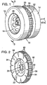
- Refer now to Fig. 1 of the drawings that illustrates a
traction device 10 mounted between a set ofdual wheels wheels dual wheels common wheel housing 16 and as shown theouter wheel 12 is spaced form theinner wheel 14. This is typical of the dual wheel mounting arrangement in which a space is provided between theouter wheel 12 and theinner wheel 14. Note from Fig. 3 that therim 13 of both of the innerdual wheel 14 and outerdual wheels 12 are mounted to thewheel housing 16 on conventional mounting lugs 15 (or bolts) that retain theinner wheel 14 andouter wheel 12 securely onto thewheel housing 16. The configuration of therims 13 of theouter wheel 12 and theinner wheel 14 positions thewheels - The
traction device 10 not assembled to the dual tires is illustrated in Figs. 2 and 4. Thetraction device 10 has arim 22 on which atire 24 of thetraction device 10 is mounted. Therim 22 hasholes 26 that are alignable with the mounting lugs orbolts 15 of thewheel housing 16. A valve stem 28 (Fig. 2) is provided to inflate thetire 24 by pressurized air and to deflate thetire 24 by exhausting the pressurized air. Thetire 24 of thetraction device 10 hasstuds 20 extending from itsperipheral surface 32. Thetire 24 hasexpansion slots 30 that are arranged to permit the radial expansion and contraction of thetire 24. As shown, theslots 30 extend across theperipheral surface 32 of thetire 24 and extend into theside walls tire 24 is arranged to expand radially as pressurized air is introduced via thevalve stem 28. - The introduction of pressurized air through the
valve stem 28 to the interior of thetire 24 will force thetire 24 to expand radially outward and thus increase its diameter. Theslots 30 are configured to enhance the uniform radial expansion of theLire 24 and to minimize the axial or lateral expansion of thetire 24. - The mounting arrangement of the
traction device 10 is further illustrated in the sectional view of Fig. 3. In this example, thewheels numbers Wheels rim 13 that has a hole pattern that mates with the conventional mounting lugs of thewheel assembly 16. - As shown in Fig. 3, the
rim 22 of thetraction device 10 is sandwiched between therims 13 of theinner wheel 14 andouter wheel 12. Therim 13 of thewheels rim 22 of thetraction device 10 are mounted to thewheel assembly 16 and are secured by the mounting lugs orbolts 15. Thetraction device 10 is thus rotatable with thewheels rim 13 of thewheels 12. This provides access to thevalve stem 28 for inflating and deflating thetire 24 of thetraction device 10. As shown in the figure, thetire 24 of thetraction device 10 is illustrated in the deflated state (contracted) in solid lines and thetire 24 is shown in the inflated (expanded) state in dashed lines. In the contracted state, thetire 24 has been deflated to contract radially inward and thus the diameter of thetire 24 is less than the diameter of thewheels tire 24 has been inflated with pressurized air to expand the tire radially to exceed the diameter of thewheels - The illustration of the
tire 24 in the expanded state is exaggerated for illustrative purposes. Thetire 24 is expanded such that thestuds 20 will extend beyond the diameter of thewheels wheels tire 24 provides the traction. - Referring to the dashed outline of the
tire 24 of thetraction device 10 of Figs. 3 and 4 (which shows thetraction device 10 in the expanded state) thetire 24 has been inflated by pressurized air. Thetire 24 has expanded radially such that the diameter of thetire 24 is greater than thewheels studs 20, when thetire 24 is in the expanded state, will extend beyond the diameter of thewheels studs 20 in engagement with the roadway R will provide the necessary traction required when the vehicle encounters slippery surfaces caused by ice, snow and the like. (The representation of ice/snow covering S and the projection of the studs to the roadway R is illustrative only of the expandability function of the invention and is not intended to accurately depict the manner by which gripping occurs, e.g., the studs in packed snow or ice conditions will not necessarily penetrate through to the bare roadway.) - Fig. 5 illustrates another known mounting arrangement for dual wheels on a vehicle. The
wheels wheel 42 can be mounted in the position ofwheel 44 and vice versa.Wheels rim 46 that is mountable onto awheel housing spider 48. The conventional mounting of thewheels spacer 50 positioned on thespider 48 between thewheels spacer 50 is provided to space thewheels wheel spider 48. In this example, thespacer 50 is altered to support thetraction device 10. Thespacer 50 includes awheel supporting rim 52 on which thetire 24 of thetraction device 10 is mounted. The valve stem 28 is extended through ahole 54 provided in thespacer 50 with thevalve stem 28 extending between twoadjacent spiders 48. Thetire 24 of the traction device is inflated to increase the diameter of thetire 24 to that which is larger than thewheels tire 24 is deflated to contract thetire 24 radially inward such that its diameter is less than thewheels - Fig. 6 illustrates the
traction device 10 arranged for use with asingle wheel 70. As shown, thetraction device 10 and thewheel 70 are mounted to awheel assembly 78 on conventional mounting lugs. Thewheel 70 has arim 72 configured to fit against therim 22 of thetraction device 10. Therim 72 has anopening 74 through which thevalve stem 28 protrudes. Thetire 24 of thetraction device 10 is illustrated in the contracted state in solid line and in the expanded state in dashed lines. It is contemplated that thetire 24 may be constructed to have radial as opposed to axial expansion and alternatively a side plate 27 (in phantom lines) may be secured to the tire rim or otherwise to take the place of the moving dual wheel and force radial expansion. - The
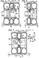
tire 24 of the traction device is inflated by conventional air sources, such as a compressed air tank. Thetire 24 of eachtraction device 24 mounted on a vehicle may be individually inflated by manually applying pressurized air to eachtire 24. Most large dual wheel vehicles have their own on board air source to provide air to the vehicle brakes, air horn and the like. Eachtire 24 may thus be coupled to the air source by suitable controls and air lines to remotely inflate and deflate thetires 24 of thetraction devices 10. Referring to Fig. 7, anair line 80 is coupled to thevalve stem 28 of thetire 24 of thetraction device 10. Theair line 80 extends through thewheel housing 16 and is coupled to anair line 82 that extends to control valve(s) 84. Thecontrol valve 84 is connected to anair supply tank 88 of the vehicle by anair line 86.Additional air lines 82 are provided to couple thecontrol valve 84 to each of the wheel housings 16 (and thus each tire 24). Thecontrol valve 84 preferably is arranged to supply air to inflate eachtire 24 or deflate each tire either individually or simultaneously. The operator of the vehicle may thus inflate or deflate thetires 24 remotely without the need of Stopping the vehicle. - Referring now to the embodiments of Figs. 8- 21 Figs. 8 and 9 of the drawings illustrate a traction device applied to a
single wheel 100.Studs 20 are provided at spaced intervals along the center of thetread portion 102. Thecenter tread portion 102 in combination with thetire wall 104 forms anexpandable chamber 106 as shown in Fig. 9. Ahose 108 connects thechamber 106 to a valve stem 110 (valve mechanism) to permit applying air pressure to thechamber 106 or relieving air pressure from thechamber 106. Air pressure is applied by a known air source, either remote or self contained on the vehicle. Thechamber 106 is shown in the expanded state in Fig. 9 which forces thecenter tread portion 102 outwardly with reference to thewheel 100 to thus place thestuds 20 into engagement with the ground surface. Fig. 8 shows thechamber 106 collapsed. That is, the air has been released from thechamber 106 and the natural resilience of thecenter tread portion 102 retracts thestuds 20 inwardly toward thetire wall 104. - Figs. 10 and 11 illustrate another traction device applied to a
wheel 120. Acenter tread portion 122 is provided between the side treads 124 and 126.Studs 20 are provided at spaced intervals along thecenter tread portion 122. Thecenter tread portion 122 is expandable as shown in Fig. 11 and is contractible as shown in Fig. 10. Thecenter tread portion 122 is expanded by the application of air pressure to achamber 127 formed within thecenter tread portion 122 and is contractible by releasing the air from thechamber 127. Ahose 128 couples thechamber 127 to avalve stem 130. Thecenter tread portion 122 in the expanded state as is shown in Fig. 11 places thestuds 20 in contact with the road surface to provided added traction. - Figs. 12 and 13 illustrate a traction device similar to those of Figs. 8 and 9 except that in Figs. 12 and 13
studs 20 are provided near eachside edge 133 of thetire tread 132 on thewheel 121. Anexpandable chamber 134 is provided for each row ofstuds 20. Ahose 136 couples each of thechambers 134 to avalve stem 138. Thechambers 134 are expandable as shown in Fig. 13 and are contractible as shown in Fig. 12. Thechambers 134 are expanded by applying air pressure to thechambers 134 and thechambers 134 are contracted by releasing the air from thechambers 134. When thechambers 134 are expanded, thestuds 20 are moved radially outward to contact the road surface. - Figs. 14 and 15 are similar to the traction devices of Figs. 12 and 13 except that the
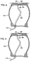
chambers 134 are joined by aduct 142 provided in thetread 132 of thewheel 140. Preferablymultiple ducts 142 are provided at spaced intervals along the length of thechambers 134. As shown in Figs. 14 and 15, asingle hose 146 is coupled to one of thechambers 134 and is connected to avalve stem 148. Thechambers 134 are shown in the expanded state in Fig. 15 and are expanded by the application of air pressure. Fig. 14 illustrates thechambers 134 in the contracted or collapsed state and thechamber 134 is collapsed by releasing the air applied to thechamber 134. - Figs. 16 and 17 illustrate another traction device applied to a
wheel 150. In this example,studs 20 are provided at spaced intervals in two rows around the periphery of thewheel 150. Thestuds 20 project from a tread portion 152 of thewheel 150. Thewheel 150 hasside tread sections center tread section 158. Each of thetread sections chamber 160 that is expandable and contractible. Ahose 162 connects thechambers 160 to avalve stem 164. Thechambers 160 are collapsible as illustrated in Fig. 16 to place thestuds 20 in contact with the road surface. Thechambers 160 are expandable as shown in Fig. 17 with thetread sections studs 20 to thus keep thestuds 20 out of contact with the road surface. - Figs. 18 and 19 illustrate a traction device as applied to a
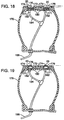
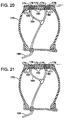
single wheel 170. In this, example thewheel 170 has a tread 172. The tread 172 haschannels 174 formed around its periphery with thechannels 174 being of a depth to receive replaceabletubular section 176. Thetubular section 176 is provided withstuds 20. Thetubular section 176 is removably mounted in thechannels 174 provided in the tire tread 172. The profile of thechannels 174 in the tread 172 will have a profile that matches the profile of the tubular section 176 (see Fig. 23). The tubular section has sufficient elasticity such that they may be installed and removed on thewheel 170 as required. Thetubular section 176 withstuds 20 would be installed on thewheel 170 when additional traction is required such as in ice or snowy conditions and thestuds 20 will provide the added traction required. Eachtubular portion 176 is inflatable (expandable) by pressurized air and as shown in Figs. 18, 19, thetubular portion 176 has astem 180 that extends through anaperture 171 into the cavity portion of thewheel 170. Acoupler 182 connects the stems 180 to anair line 184.Air line 184 is connected to aconventional valve stem 186 for inflating and deflating thetubular portion 176. Thetubular portion 176 is contractible by releasing the pressurized air. - The
tubular portion 176 is inflated by pressurized air so that thetubular portion 176 will be substantially even with the tread 172 of thewheel 170. When thetubular portion 176 is inflated to be even with the tread 172, thestuds 20 will project beyond the tread 172 and thestuds 20 of thetubular portion 176 thus will be in contact with the ground surface to provide additional traction. -
Tubular portion 178, as illustrated in Figs. 20 and 21, is a filler unit that is most often utilized when additional traction afforded by thestuds 20 is not required such as during the summer months. Thetubular portion 178 when inflated (Fig. 21) will have its upper surface substantially even with the tread 172 of thewheel 170. Thetubular portion 178 has a profile that will mate with the profile of the channel 174 (Fig. 21). Thetubular portion 178 has astem 180 that extends through theaperture 171 into the cavity portion of thewheel 170. Acoupler 182 connects thestem 184 to anair line 184.Air line 184 is connected to aconventional valve stem 186 for inflating and deflating the tubular portion 173.
Claims (7)
- A wheel hub and tire for mounting to a vehicle comprising:a wheel hub, a tire mounted on said wheel hub, said tire having a normally inflated inflatable primary chamber, said primary chamber defining a circumferential wall including side wall portions and a bottom wall portion (104) extending substantially linearly between said side wall portions, characterised by: an integral tread layer (102) overlying and in major supportive contact with the bottom wall portion (104) including first and second circumferential tread segments secured to said bottom wall portion (104) for engaging a road surface;a secondary chamber (106) provided between one of said first and second tread segments and the bottom wall portion (104) and a fluid source and fluid control (108,110) connected to said secondary chamber (104), said first and second tread segments structured to have one only of said tread segments engaging a road surface and alternatively both of the said segments engaging a road surface in response to inflation or deflation of said secondary chamber, andstuds (20) fixedly mounted in one of said tread segments and arranged to extend into a road surface for gripping engagement of the road surface only with both of said segments engaging the road surface.
- A wheel hub and tire as defined in claim 1, wherein the integral tread layer further includes a third segment, said second tread segment being the stud bearing tread segment and positioned between said first and third tread segments both being non-stud bearing segments, said secondary chamber positioned between said circumferential wall and said second tread segment, said second tread segment being in non-engaging relation to said road surface with the secondary chamber not inflated, and in engaging relation to said road surface with the secondary chamber inflated.
- A wheel hub and tire as defined in claim 1, wherein the integral tread layer further includes a third tread segment, said second tread segment being the stud bearing tread segment and positioned between said first and third tread segments both being non-stud bearing segments, said secondary chamber positioned between said circumferential wall and said first and third tread segments, said second tread segments being in non-engaging relation to said road surface with the secondary chamber inflated and in engaging relation to said road surface with the secondary chamber not inflated.
- A tire for mounting on a wheel hub and arranged with a normally inflated inflatable primary chamber, said primary chamber defining a circumferential wall including side wall portions and a bottom wall portion (104) extending substantially linearly between said side wall portions, characterised by : an integral tread layer (102) overlying and in major supportive contact with the bottom wall portion (104) including first and second circumferential tread segments secured to said bottom wall portion (104) for engaging a road surface;
a secondary chamber (106) provided between one of said first and second tread segments and the bottom wall portion (104) and a fluid source and fluid control (108, 110) connected to said secondary chamber (104), said first and second tread segments structured to have one only of said tread segments engaging a road surface and alternatively both of the said segments engaging a road surface in response to inflation or deflation of said secondary chamber, and
studs (20) fixedly mounted in one of said tread segments and arranged to extend into a road surface for gripping engagement of the road surface only with both of said segments engaging the road surface. - A wheel as defined in claim 1, wherein the secondary chamber is associated with the stud bearing tread segment and is positioned between the primary chamber when inflated and the stud bearing tread segment whereby inflation of the secondary chamber forces extension of the stud bearing tread segment into contact with the road surface.
- A wheel as defined in claim 1, wherein the secondary inflatable chamber is positioned between the primary chamber when inflated and the non-stud bearing tread segments whereby inflation of the secondary chamber forces extension of the non-stud bearing tread segments beyond the stud bearing segment to place the stud bearing segment out of contact with the road surface.
- A method for forming a wheel hub and tire combination comprising:providing a wheel hub;forming a tire including the steps of forming a first layer to define a primary inflatable chamber;forming a second, separate, one piece layer on the first layer as the outermost circumferential portion of the tire and in major supportive contact with the first layer including at least one non-stud bearing tread segment and at least one stud bearing tread segment;forming a secondary inflatable chamber between the first layer and one of the tread segments of the second layer;providing an inlet control selectively providing the inflation and deflation of the secondary chamber;selectively inflating and deflating the secondary chamber to selectively place the stud bearing tread segment in contact with the road surface and out of contact with the road surface; and mounting the tire on wheel hub.
Applications Claiming Priority (5)
| Application Number | Priority Date | Filing Date | Title |
|---|---|---|---|
| US909302 | 1986-09-19 | ||
| US08/733,676 US5788335A (en) | 1996-10-17 | 1996-10-17 | Traction device for vehicle wheels |
| US733676 | 1996-10-17 | ||
| US08/909,302 US5810451A (en) | 1996-10-17 | 1997-08-11 | Traction device for vehicle wheels |
| PCT/US1997/019454 WO1998016399A1 (en) | 1996-10-17 | 1997-10-17 | Traction device for vehicle wheels |
Publications (3)
| Publication Number | Publication Date |
|---|---|
| EP0930980A1 EP0930980A1 (en) | 1999-07-28 |
| EP0930980A4 EP0930980A4 (en) | 2002-10-02 |
| EP0930980B1 true EP0930980B1 (en) | 2006-04-26 |
Family
ID=27112611
Family Applications (1)
| Application Number | Title | Priority Date | Filing Date |
|---|---|---|---|
| EP97911939A Expired - Lifetime EP0930980B1 (en) | 1996-10-17 | 1997-10-17 | Traction device for vehicle wheels |
Country Status (11)
| Country | Link |
|---|---|
| US (3) | US5810451A (en) |
| EP (1) | EP0930980B1 (en) |
| JP (1) | JP2001524043A (en) |
| AT (1) | ATE324274T1 (en) |
| AU (1) | AU4920197A (en) |
| CA (1) | CA2269071C (en) |
| DE (1) | DE69735765T2 (en) |
| DK (1) | DK0930980T3 (en) |
| ES (1) | ES2264161T3 (en) |
| PT (1) | PT930980E (en) |
| WO (1) | WO1998016399A1 (en) |
Cited By (2)
| Publication number | Priority date | Publication date | Assignee | Title |
|---|---|---|---|---|
| WO2012034545A1 (en) | 2010-09-14 | 2012-03-22 | Technicka Univerzita V Liberci | Travelling vehicle wheel |
| WO2015070270A1 (en) | 2013-11-12 | 2015-05-21 | Würkner Gerald | Device for improving the grip of a vehicle tyre |
Families Citing this family (43)
| Publication number | Priority date | Publication date | Assignee | Title |
|---|---|---|---|---|
| US5810451A (en) * | 1996-10-17 | 1998-09-22 | O'brien; John Michael | Traction device for vehicle wheels |
| US6022082A (en) * | 1996-10-17 | 2000-02-08 | Traction On Demand Llc | Traction device for vehicle wheels |
| US6905564B1 (en) * | 1996-10-17 | 2005-06-14 | Power Cleat, Ltd. | Process for creating expandable tire chamber |
| EP0909666B1 (en) * | 1997-09-16 | 2004-06-16 | Kinzo Hatta | Tire having anti-slip properties |
| US6581661B1 (en) | 1999-07-10 | 2003-06-24 | Large Car Equipment And Apparel, Llc | Apparatus for improving tire traction |
| US6615888B2 (en) * | 2001-10-15 | 2003-09-09 | Douglas B. Elkow | Variable-diameter wheel-and-tire apparatus for motor vehicles |
| US6637834B2 (en) | 2001-10-15 | 2003-10-28 | Douglas B. Elkow | Variable-diameter wheel apparatus for motor vehicles |
| WO2004005048A1 (en) * | 2002-07-08 | 2004-01-15 | John Maltzahn | All-terrain vehicle |
| SE524746C2 (en) * | 2003-02-13 | 2004-09-28 | Sven A Jansson | vehicle Wheels |
| US6918544B2 (en) * | 2003-02-18 | 2005-07-19 | Clay Ferguson | Automobile traction devices |
| US20050092411A1 (en) * | 2003-10-31 | 2005-05-05 | O'brien John M. | Tire having expandable tread portion |
| US7252728B2 (en) * | 2004-07-12 | 2007-08-07 | The Goodyear Tire & Rubber Company | Method for forming a pneumatic tire |
| US20080066348A1 (en) * | 2005-02-07 | 2008-03-20 | Select Sole, Llc | Footwear with retractable members |
| US7234250B2 (en) * | 2005-02-07 | 2007-06-26 | Stacy Renee Fogarty | Convertible traction shoes |
| KR100738649B1 (en) | 2005-03-23 | 2007-07-11 | 금호타이어 주식회사 | Pneumatic Tire improved running performance |
| US7291237B2 (en) * | 2005-03-24 | 2007-11-06 | O'brien John Michael | Method of making tire having wear indicators |
| FR2885844B1 (en) * | 2005-05-17 | 2007-07-27 | Philippe Biesse | RIM ANTI-ENLISEMENT |
| CN101007492B (en) * | 2006-01-27 | 2010-05-12 | 蓝进 | Safe tyre and its production method and method for promoting traffic safety using the tyre |
| JP3123417U (en) * | 2006-05-02 | 2006-07-20 | 株式会社アイメック | Vibration isolator for truck loader type vehicle |
| US20080047645A1 (en) * | 2006-08-24 | 2008-02-28 | Jon Stuart Gerhardt | tractive tire method and apparatus |
| US7784196B1 (en) * | 2006-12-13 | 2010-08-31 | Reebok International Ltd. | Article of footwear having an inflatable ground engaging surface |
| US20080190531A1 (en) * | 2007-02-09 | 2008-08-14 | Mabra Holeyfield | Snow and Ice Patch For Tires |
| US20090114322A1 (en) * | 2007-11-06 | 2009-05-07 | O'brien Pat | Tread marker, tire with integral tread markers, and methods for producing both |
| US8082961B2 (en) * | 2007-12-31 | 2011-12-27 | The Goodyear Tire & Rubber Company | Tire with retractable stud |
| US8186985B2 (en) * | 2009-12-17 | 2012-05-29 | The Goodyear Tire & Rubber Company | Mold apparatus for forming grooves in tire shoulder |
| US9744804B2 (en) | 2010-09-27 | 2017-08-29 | Kendall W Pope | Multi-diameter tire and wheel assembly for improved vehicle mileage with passive transfer between tire diameters |
| US9278584B2 (en) * | 2011-10-31 | 2016-03-08 | Innovative Technologies, Llc | All-weather tire |
| US9290057B2 (en) * | 2011-10-31 | 2016-03-22 | Innovative Technologies, Llc | All season safety tire |
| US20130153082A1 (en) * | 2011-12-14 | 2013-06-20 | International Business Machines Corporation | Variable friction tires |
| CN102555665A (en) * | 2012-02-16 | 2012-07-11 | 杜增辉 | Antiskid method for running of automobile in winters and inflatable external antiskid wheel used for antiskid method |
| JP6007592B2 (en) * | 2012-05-22 | 2016-10-12 | 横浜ゴム株式会社 | Tire and wheel assembly and electric vehicle |
| CZ24299U1 (en) | 2012-07-09 | 2012-09-10 | Gross@Petr | Non-skid device for automobile wheels |
| CA3034727C (en) | 2012-08-20 | 2019-10-22 | Ice Adaptive Tires, LLC | Ice adaptive tire system |
| ES2423083B1 (en) * | 2013-05-16 | 2014-09-02 | Seat, S.A. | Automatic tire deflation system of a motor vehicle, and double chamber tire for the same |
| KR102137829B1 (en) * | 2014-10-06 | 2020-07-27 | 현대자동차주식회사 | Variable tire |
| US9855800B2 (en) * | 2016-02-22 | 2018-01-02 | The Goodyear Tire & Rubber Company | Tripletube tire |
| KR101732427B1 (en) | 2016-03-07 | 2017-05-24 | 김종태 | Mounting apparatus for a assistance wheel of dolly |
| KR102351638B1 (en) * | 2017-09-04 | 2022-01-17 | 현대건설기계 주식회사 | Double Tire Protector, Double Tire Having the Same and Vehicle Having the Double Tire |
| CN108284705A (en) * | 2018-01-25 | 2018-07-17 | 安徽港泰机械制造集团有限公司 | A kind of portable type rail-road car wheel with long service life |
| PL425275A1 (en) * | 2018-04-19 | 2019-10-21 | Rybka Piotr P.P.H.U. Rybka-Globgum 3 | Car tyre for practice driving and method for making the tread of that tyre |
| FR3087085B1 (en) * | 2018-10-12 | 2021-01-29 | Otico | SELF-CLEANING AGRICULTURAL ROLLER |
| US11458761B2 (en) * | 2019-10-01 | 2022-10-04 | Joe Cindrich | Traction system for vehicle |
| WO2023061518A1 (en) * | 2021-10-14 | 2023-04-20 | Technicka Univerzita V Liberci | Adaptive vehicle wheel |
Citations (2)
| Publication number | Priority date | Publication date | Assignee | Title |
|---|---|---|---|---|
| DE2100334A1 (en) * | 1970-01-08 | 1971-07-22 | Cadhni, Alberto, Haldenstein (Schweiz) | Season tires, convertible on the spot from summer tires to winter tires for snow and ice, and vice versa |
| JPS59164208A (en) * | 1983-03-04 | 1984-09-17 | Hiroyuki Ito | Spike tire |
Family Cites Families (59)
| Publication number | Priority date | Publication date | Assignee | Title |
|---|---|---|---|---|
| FR1066702A (en) * | 1954-06-09 | |||
| FR659277A (en) | 1928-02-17 | 1929-06-26 | Polyphase electric current rectification process | |
| US1749766A (en) | 1928-08-11 | 1930-03-11 | Hitchner Tire Corp | Tire |
| FR723612A (en) * | 1931-09-10 | 1932-04-12 | Safety wheel with pneumatic tires for automobiles or other similar vehicles | |
| US2079501A (en) * | 1935-10-19 | 1937-05-04 | Gerald R Gallagher | Antiskid device |
| US2201632A (en) * | 1937-09-15 | 1940-05-21 | Elmon C Gillette | Antiskidding device for automobiles |
| US2174944A (en) * | 1937-11-16 | 1939-10-03 | Rae H Leggett | Vehicle wheel traction means |
| US2377923A (en) * | 1938-12-22 | 1945-06-12 | Aloysius J Cawley | Road engaging means for automobiles or the like |
| US2254318A (en) * | 1939-02-04 | 1941-09-02 | Louis Otto E Roessel | Traction device |
| US2241849A (en) * | 1940-02-07 | 1941-05-13 | Arthur S Kee | Nonskid mechanism for dual wheels |
| FR1006702A (en) * | 1947-08-19 | 1952-04-28 | Geigy Ag J R | Process for the preparation of ethylene diamine derivatives |
| US2480548A (en) | 1948-08-02 | 1949-08-30 | William H Carhart | Vehicle tire |
| BE495802A (en) * | 1949-05-23 | |||
| US2559721A (en) * | 1950-05-16 | 1951-07-10 | John J Kruse | Ice gripper for vehicle wheels |
| US2708470A (en) | 1952-02-20 | 1955-05-17 | Clarence U Gramelspacher | Tire construction |
| US2751959A (en) * | 1953-06-11 | 1956-06-26 | Fairchild Engine And Aiplane C | Vehicle wheel |
| US2835302A (en) | 1955-12-30 | 1958-05-20 | Gedge Thomas James | Adjustable pneumatic tire |
| US2765199A (en) * | 1956-02-17 | 1956-10-02 | Earl E Partin | Anti-skid wheel assembly |
| AT198148B (en) * | 1957-04-24 | 1958-06-10 | Wenzel Schlifelner | Anti-skid device for motor vehicles |
| US2926720A (en) | 1957-08-02 | 1960-03-01 | Gosman Clarence Berveir | Method of and apparatus for making inflatable articles |
| US2903037A (en) * | 1958-03-17 | 1959-09-08 | Fred L Palmer | Traction attachment for wheels |
| US3110339A (en) | 1962-01-02 | 1963-11-12 | Lawrence K Fickel | Ventilated pneumatic tire structure and method of fabricating the tire |
| US3942572A (en) | 1974-01-15 | 1976-03-09 | Crandall Azel L | Multicelled, tubeless safety tire with air activated snow and ice studs |
| NL7400507A (en) * | 1974-01-15 | 1975-07-17 | Lely Nv C Van Der | ANTI-SLIP DEVICE FOR A VEHICLE, ESPECIALLY AN AGRICULTURAL TRACTOR. |
| US5109905A (en) | 1977-12-01 | 1992-05-05 | Lambe Donald M | Dual chamber pneumatic tire with the chambers separated by a collapsible partition wall |
| US4293017A (en) | 1977-12-01 | 1981-10-06 | Lambe Donald M | Dual-chamber pneumatic tire |
| DE2901606A1 (en) * | 1979-01-17 | 1980-07-31 | Schmitt Baugeraetevermittlung | Insert for heavy vehicle twin wheels - comprises shaped reinforced belt with outer tread to prevent entry of stones or debris |
| DE3001483A1 (en) * | 1980-01-17 | 1981-07-23 | Dietmar 2071 Hamfelde Heidemann | Vehicle wheel snow grip - has second tyre with studded tread selectively inflatable for contact with road |
| JPS58122207A (en) | 1982-01-12 | 1983-07-20 | Kinya Nakamura | Anti-spinning tyre which protrudes and retracts |
| JPS59114103A (en) | 1982-12-17 | 1984-07-02 | Kinya Nakamura | Anti-slipping tire with projectable tread |
| FR2556656B1 (en) * | 1983-12-14 | 1988-04-22 | Amara Mohand | ANTI-PITCHING SAFETY ACCESSORY, ANTI-LOCK WHEELS, ANTI-SLIP |
| US4676289A (en) * | 1984-08-13 | 1987-06-30 | Cherng Yi Su | Automobile tire having retractable tread studs |
| US4909972A (en) | 1985-12-02 | 1990-03-20 | Britz Johannes H | Method and apparatus for making a solid foamed tire core |
| US4803029A (en) | 1986-01-28 | 1989-02-07 | Pmt Corporation | Process for manufacturing an expandable member |
| EP0236041A3 (en) * | 1986-02-25 | 1988-09-07 | Kabushiki Kaisha Tohdoh Koumuten | Spike device for vehicles and control mechanism thereof |
| JPS62299408A (en) * | 1986-06-17 | 1987-12-26 | Masashi Kumano | Pneumatic spike tire |
| JPS6343804A (en) * | 1986-08-09 | 1988-02-24 | Natsuo Suzuki | Spike radial tire for preventing formation of dust through recession of spike by pneumatic operation |
| JPS6368408A (en) | 1986-09-09 | 1988-03-28 | Kiyohiro Hirakawa | Non-skid tire device |
| FR2607757B1 (en) | 1986-12-04 | 1991-05-31 | Peugeot | DEVICE FOR SUSPENDING THE BODY AND THE DRIVE UNIT OF A MOTOR VEHICLE |
| JPS63145109A (en) | 1986-12-05 | 1988-06-17 | Mitsuya Ooba | Variable spiked snow tire |
| DE3721500A1 (en) | 1987-06-30 | 1989-01-12 | Agot Eric Joel | Retractable integrated tyre spike system (integrated spike system) |
| JPH01122708A (en) | 1987-11-07 | 1989-05-16 | Teruo Iwama | Spike tire possible to be manually changed over |
| DE3800326A1 (en) * | 1988-01-08 | 1989-07-20 | Reinhold Kuhn | Combination tyre for motor vehicles |
| CN1050866A (en) | 1989-09-19 | 1991-04-24 | 联合碳化化学品及塑料有限公司 | The silver-containing catalyst that is used for oxidative coupling |
| JPH07102762B2 (en) | 1989-11-27 | 1995-11-08 | 武昭 永井 | Car tires |
| FR2659277A1 (en) | 1990-03-09 | 1991-09-13 | Landreau Francois | Retractable device for a studded tyre, especially for the automobile |
| US5411070A (en) * | 1990-04-05 | 1995-05-02 | Yadegar; Iraj | Self-contained anti-skid device for pneumatic tires |
| DE4207613A1 (en) | 1992-03-10 | 1993-09-16 | Hans Scheibenpflug | Tyre fitted with withdrawable spikes in tread - has internal diaphragm which is cured circumferentially inside shoulder and can be pressurised to force spikes out through holes in tread |
| JPH0632111U (en) | 1992-10-07 | 1994-04-26 | 藤一 竹林 | Tire structure |
| US5609700A (en) * | 1993-11-06 | 1997-03-11 | West; Allen D. | Operator selectable "on demand" studded tire |
| US5419726A (en) | 1993-12-17 | 1995-05-30 | Switlik Parachute Company, Inc. | Inflatable flotation raft apparatus having heated seal areas and method of assembly thereof |
| JPH07276926A (en) | 1994-04-02 | 1995-10-24 | Shigeru Kato | Spike tire |
| JPH07309107A (en) | 1994-05-16 | 1995-11-28 | Shigeru Kato | Spiked tire |
| JPH08310204A (en) | 1995-05-18 | 1996-11-26 | Takatoshi Aoyama | Tire |
| DE29601450U1 (en) * | 1996-01-29 | 1996-03-07 | Seifert Adelheid | Antiskid for motor vehicles |
| US5795414A (en) | 1996-04-10 | 1998-08-18 | Shih; Choon J. | Puncture resistant tire assembly |
| US5810451A (en) * | 1996-10-17 | 1998-09-22 | O'brien; John Michael | Traction device for vehicle wheels |
| US5788335A (en) * | 1996-10-17 | 1998-08-04 | O'brien; John M. | Traction device for vehicle wheels |
| EP0909666B1 (en) * | 1997-09-16 | 2004-06-16 | Kinzo Hatta | Tire having anti-slip properties |
-
1997
- 1997-08-11 US US08/909,302 patent/US5810451A/en not_active Expired - Lifetime
- 1997-10-17 JP JP51867098A patent/JP2001524043A/en active Pending
- 1997-10-17 US US09/284,557 patent/US6386252B1/en not_active Expired - Fee Related
- 1997-10-17 DE DE69735765T patent/DE69735765T2/en not_active Expired - Fee Related
- 1997-10-17 PT PT97911939T patent/PT930980E/en unknown
- 1997-10-17 EP EP97911939A patent/EP0930980B1/en not_active Expired - Lifetime
- 1997-10-17 AU AU49201/97A patent/AU4920197A/en not_active Abandoned
- 1997-10-17 WO PCT/US1997/019454 patent/WO1998016399A1/en active IP Right Grant
- 1997-10-17 AT AT97911939T patent/ATE324274T1/en not_active IP Right Cessation
- 1997-10-17 DK DK97911939T patent/DK0930980T3/en active
- 1997-10-17 CA CA002269071A patent/CA2269071C/en not_active Expired - Fee Related
- 1997-10-17 ES ES97911939T patent/ES2264161T3/en not_active Expired - Lifetime
-
2000
- 2000-02-03 US US09/497,310 patent/US6244666B1/en not_active Expired - Fee Related
Patent Citations (2)
| Publication number | Priority date | Publication date | Assignee | Title |
|---|---|---|---|---|
| DE2100334A1 (en) * | 1970-01-08 | 1971-07-22 | Cadhni, Alberto, Haldenstein (Schweiz) | Season tires, convertible on the spot from summer tires to winter tires for snow and ice, and vice versa |
| JPS59164208A (en) * | 1983-03-04 | 1984-09-17 | Hiroyuki Ito | Spike tire |
Cited By (2)
| Publication number | Priority date | Publication date | Assignee | Title |
|---|---|---|---|---|
| WO2012034545A1 (en) | 2010-09-14 | 2012-03-22 | Technicka Univerzita V Liberci | Travelling vehicle wheel |
| WO2015070270A1 (en) | 2013-11-12 | 2015-05-21 | Würkner Gerald | Device for improving the grip of a vehicle tyre |
Also Published As
| Publication number | Publication date |
|---|---|
| PT930980E (en) | 2006-08-31 |
| DE69735765T2 (en) | 2006-11-02 |
| EP0930980A1 (en) | 1999-07-28 |
| DK0930980T3 (en) | 2006-07-31 |
| ES2264161T3 (en) | 2006-12-16 |
| WO1998016399A1 (en) | 1998-04-23 |
| DE69735765D1 (en) | 2006-06-01 |
| AU4920197A (en) | 1998-05-11 |
| US6244666B1 (en) | 2001-06-12 |
| CA2269071A1 (en) | 1998-04-23 |
| CA2269071C (en) | 2009-01-27 |
| ATE324274T1 (en) | 2006-05-15 |
| JP2001524043A (en) | 2001-11-27 |
| US5810451A (en) | 1998-09-22 |
| EP0930980A4 (en) | 2002-10-02 |
| US6386252B1 (en) | 2002-05-14 |
Similar Documents
| Publication | Publication Date | Title |
|---|---|---|
| EP0930980B1 (en) | Traction device for vehicle wheels | |
| US5788335A (en) | Traction device for vehicle wheels | |
| US6022082A (en) | Traction device for vehicle wheels | |
| US6044883A (en) | Retractable anti-skid tread for dual tire vehicles | |
| US4676289A (en) | Automobile tire having retractable tread studs | |
| US3942572A (en) | Multicelled, tubeless safety tire with air activated snow and ice studs | |
| US4059138A (en) | Run-flat tire and hub therefor | |
| US20130300185A1 (en) | Mobility device and method | |
| US4945965A (en) | Safety tube assembly for pneumatic tires | |
| AU2011312935B2 (en) | An apparatus for preventing the skidding of a vehicle provided with wheels | |
| US6109319A (en) | Run-flat support for pneumatic tired wheel | |
| US5660653A (en) | Run-flat support for pneumatic tired wheel | |
| US5609700A (en) | Operator selectable "on demand" studded tire | |
| US2775282A (en) | Vehicle wheel | |
| US2650632A (en) | Adjustable tire | |
| CA2591561A1 (en) | Traction device for vehicle wheels | |
| CA1050404A (en) | Run-flat system for a vehicle wheel | |
| US3777798A (en) | Safety wheel | |
| CA2700102A1 (en) | Extendable/retractable studs for a tire | |
| WO1999007564A1 (en) | Traction device for vehicle wheels | |
| US3506051A (en) | Traction-increasing device | |
| US2617689A (en) | Emergency wheel | |
| US1918694A (en) | Emergency tire for vehicles | |
| US1004582A (en) | Tire for vehicle-wheels. | |
| KR100286420B1 (en) | Snow spike device of tubeless tire |
Legal Events
| Date | Code | Title | Description |
|---|---|---|---|
| PUAI | Public reference made under article 153(3) epc to a published international application that has entered the european phase |
Free format text: ORIGINAL CODE: 0009012 |
|
| 17P | Request for examination filed |
Effective date: 19990415 |
|
| AK | Designated contracting states |
Kind code of ref document: A1 Designated state(s): AT BE CH DE DK ES FI FR GB GR IE IT LI LU MC NL PT SE |
|
| A4 | Supplementary search report drawn up and despatched |
Effective date: 20020816 |
|
| AK | Designated contracting states |
Kind code of ref document: A4 Designated state(s): AT BE CH DE DK ES FI FR GB GR IE IT LI LU MC NL PT SE |
|
| RIC1 | Information provided on ipc code assigned before grant |
Free format text: 7B 60B 15/00 A, 7B 60B 15/26 B, 7B 60C 27/00 B, 7B 60C 11/16 B |
|
| 17Q | First examination report despatched |
Effective date: 20030206 |
|
| GRAP | Despatch of communication of intention to grant a patent |
Free format text: ORIGINAL CODE: EPIDOSNIGR1 |
|
| GRAS | Grant fee paid |
Free format text: ORIGINAL CODE: EPIDOSNIGR3 |
|
| GRAA | (expected) grant |
Free format text: ORIGINAL CODE: 0009210 |
|
| AK | Designated contracting states |
Kind code of ref document: B1 Designated state(s): AT BE CH DE DK ES FI FR GB GR IE IT LI LU MC NL PT SE |
|
| PG25 | Lapsed in a contracting state [announced via postgrant information from national office to epo] |
Ref country code: IT Free format text: LAPSE BECAUSE OF FAILURE TO SUBMIT A TRANSLATION OF THE DESCRIPTION OR TO PAY THE FEE WITHIN THE PRESCRIBED TIME-LIMIT;WARNING: LAPSES OF ITALIAN PATENTS WITH EFFECTIVE DATE BEFORE 2007 MAY HAVE OCCURRED AT ANY TIME BEFORE 2007. THE CORRECT EFFECTIVE DATE MAY BE DIFFERENT FROM THE ONE RECORDED. Effective date: 20060426 |
|
| REG | Reference to a national code |
Ref country code: GB Ref legal event code: FG4D |
|
| REG | Reference to a national code |
Ref country code: IE Ref legal event code: FG4D |
|
| REF | Corresponds to: |
Ref document number: 69735765 Country of ref document: DE Date of ref document: 20060601 Kind code of ref document: P |
|
| REG | Reference to a national code |
Ref country code: SE Ref legal event code: TRGR |
|
| REG | Reference to a national code |
Ref country code: DK Ref legal event code: T3 |
|
| REG | Reference to a national code |
Ref country code: PT Ref legal event code: SC4A Effective date: 20060712 Ref country code: CH Ref legal event code: NV Representative=s name: ISLER & PEDRAZZINI AG |
|
| REG | Reference to a national code |
Ref country code: GR Ref legal event code: EP Ref document number: 20060402579 Country of ref document: GR |
|
| PG25 | Lapsed in a contracting state [announced via postgrant information from national office to epo] |
Ref country code: IE Free format text: LAPSE BECAUSE OF NON-PAYMENT OF DUE FEES Effective date: 20061017 |
|
| PG25 | Lapsed in a contracting state [announced via postgrant information from national office to epo] |
Ref country code: MC Free format text: LAPSE BECAUSE OF NON-PAYMENT OF DUE FEES Effective date: 20061031 Ref country code: DK Free format text: LAPSE BECAUSE OF NON-PAYMENT OF DUE FEES Effective date: 20061031 |
|
| ET | Fr: translation filed | ||
| RAP2 | Party data changed (patent owner data changed or rights of a patent transferred) |
Owner name: Q TIRES, INC |
|
| RIN2 | Information on inventor provided after grant (corrected) |
Inventor name: Q TIRES, INC |
|
| REG | Reference to a national code |
Ref country code: ES Ref legal event code: FG2A Ref document number: 2264161 Country of ref document: ES Kind code of ref document: T3 |
|
| NLT2 | Nl: modifications (of names), taken from the european patent patent bulletin |
Owner name: Q TIRES, INC Effective date: 20061213 |
|
| PLBE | No opposition filed within time limit |
Free format text: ORIGINAL CODE: 0009261 |
|
| STAA | Information on the status of an ep patent application or granted ep patent |
Free format text: STATUS: NO OPPOSITION FILED WITHIN TIME LIMIT |
|
| 26N | No opposition filed |
Effective date: 20070129 |
|
| PG25 | Lapsed in a contracting state [announced via postgrant information from national office to epo] |
Ref country code: NL Free format text: LAPSE BECAUSE OF NON-PAYMENT OF DUE FEES Effective date: 20070501 |
|
| REG | Reference to a national code |
Ref country code: GB Ref legal event code: 732E |
|
| NLV4 | Nl: lapsed or anulled due to non-payment of the annual fee |
Effective date: 20070501 |
|
| REG | Reference to a national code |
Ref country code: FR Ref legal event code: TP Ref country code: FR Ref legal event code: CJ Ref country code: FR Ref legal event code: CD |
|
| PG25 | Lapsed in a contracting state [announced via postgrant information from national office to epo] |
Ref country code: PT Free format text: LAPSE BECAUSE OF NON-PAYMENT OF DUE FEES Effective date: 20070717 |
|
| REG | Reference to a national code |
Ref country code: PT Ref legal event code: MM4A Free format text: LAPSE DUE TO NON-PAYMENT OF FEES Effective date: 20070717 |
|
| REG | Reference to a national code |
Ref country code: CH Ref legal event code: PCAR Free format text: ISLER & PEDRAZZINI AG;POSTFACH 1772;8027 ZUERICH (CH) |
|
| BERE | Be: lapsed |
Owner name: *O'BRIEN JOHN M. Effective date: 20061031 |
|
| PGFP | Annual fee paid to national office [announced via postgrant information from national office to epo] |
Ref country code: ES Payment date: 20071120 Year of fee payment: 11 Ref country code: DE Payment date: 20071011 Year of fee payment: 11 |
|
| PGFP | Annual fee paid to national office [announced via postgrant information from national office to epo] |
Ref country code: AT Payment date: 20071011 Year of fee payment: 11 Ref country code: CH Payment date: 20071015 Year of fee payment: 11 Ref country code: FI Payment date: 20071012 Year of fee payment: 11 Ref country code: IT Payment date: 20071027 Year of fee payment: 11 |
|
| PGFP | Annual fee paid to national office [announced via postgrant information from national office to epo] |
Ref country code: SE Payment date: 20071004 Year of fee payment: 11 |
|
| PG25 | Lapsed in a contracting state [announced via postgrant information from national office to epo] |
Ref country code: GR Free format text: LAPSE BECAUSE OF NON-PAYMENT OF DUE FEES Effective date: 20060727 |
|
| PGFP | Annual fee paid to national office [announced via postgrant information from national office to epo] |
Ref country code: GB Payment date: 20071017 Year of fee payment: 11 Ref country code: FR Payment date: 20071009 Year of fee payment: 11 |
|
| PG25 | Lapsed in a contracting state [announced via postgrant information from national office to epo] |
Ref country code: LU Free format text: LAPSE BECAUSE OF NON-PAYMENT OF DUE FEES Effective date: 20061017 |
|
| REG | Reference to a national code |
Ref country code: CH Ref legal event code: PL |
|
| EUG | Se: european patent has lapsed | ||
| GBPC | Gb: european patent ceased through non-payment of renewal fee |
Effective date: 20081017 |
|
| REG | Reference to a national code |
Ref country code: FR Ref legal event code: ST Effective date: 20090630 |
|
| PG25 | Lapsed in a contracting state [announced via postgrant information from national office to epo] |
Ref country code: FI Free format text: LAPSE BECAUSE OF NON-PAYMENT OF DUE FEES Effective date: 20081017 |
|
| PG25 | Lapsed in a contracting state [announced via postgrant information from national office to epo] |
Ref country code: IT Free format text: LAPSE BECAUSE OF NON-PAYMENT OF DUE FEES Effective date: 20081017 Ref country code: DE Free format text: LAPSE BECAUSE OF NON-PAYMENT OF DUE FEES Effective date: 20090501 Ref country code: BE Free format text: LAPSE BECAUSE OF FAILURE TO SUBMIT A TRANSLATION OF THE DESCRIPTION OR TO PAY THE FEE WITHIN THE PRESCRIBED TIME-LIMIT Effective date: 20061031 Ref country code: AT Free format text: LAPSE BECAUSE OF NON-PAYMENT OF DUE FEES Effective date: 20081017 |
|
| PG25 | Lapsed in a contracting state [announced via postgrant information from national office to epo] |
Ref country code: LI Free format text: LAPSE BECAUSE OF NON-PAYMENT OF DUE FEES Effective date: 20081031 Ref country code: FR Free format text: LAPSE BECAUSE OF NON-PAYMENT OF DUE FEES Effective date: 20081031 Ref country code: CH Free format text: LAPSE BECAUSE OF NON-PAYMENT OF DUE FEES Effective date: 20081031 |
|
| PG25 | Lapsed in a contracting state [announced via postgrant information from national office to epo] |
Ref country code: GB Free format text: LAPSE BECAUSE OF NON-PAYMENT OF DUE FEES Effective date: 20081017 |
|
| REG | Reference to a national code |
Ref country code: ES Ref legal event code: FD2A Effective date: 20081018 |
|
| PG25 | Lapsed in a contracting state [announced via postgrant information from national office to epo] |
Ref country code: ES Free format text: LAPSE BECAUSE OF NON-PAYMENT OF DUE FEES Effective date: 20081018 |
|
| PG25 | Lapsed in a contracting state [announced via postgrant information from national office to epo] |
Ref country code: SE Free format text: LAPSE BECAUSE OF NON-PAYMENT OF DUE FEES Effective date: 20081018 |