EP0930771A2 - Kompaktes Multifunktionsgerät - Google Patents
Kompaktes Multifunktionsgerät Download PDFInfo
- Publication number
- EP0930771A2 EP0930771A2 EP98310799A EP98310799A EP0930771A2 EP 0930771 A2 EP0930771 A2 EP 0930771A2 EP 98310799 A EP98310799 A EP 98310799A EP 98310799 A EP98310799 A EP 98310799A EP 0930771 A2 EP0930771 A2 EP 0930771A2
- Authority
- EP
- European Patent Office
- Prior art keywords
- sheet conveying
- printhead
- record sheet
- carriage
- service station
- Prior art date
- Legal status (The legal status is an assumption and is not a legal conclusion. Google has not performed a legal analysis and makes no representation as to the accuracy of the status listed.)
- Ceased
Links
Images


Classifications
-
- G—PHYSICS
- G06—COMPUTING; CALCULATING OR COUNTING
- G06K—GRAPHICAL DATA READING; PRESENTATION OF DATA; RECORD CARRIERS; HANDLING RECORD CARRIERS
- G06K7/00—Methods or arrangements for sensing record carriers, e.g. for reading patterns
-
- H—ELECTRICITY
- H04—ELECTRIC COMMUNICATION TECHNIQUE
- H04N—PICTORIAL COMMUNICATION, e.g. TELEVISION
- H04N1/00—Scanning, transmission or reproduction of documents or the like, e.g. facsimile transmission; Details thereof
- H04N1/04—Scanning arrangements, i.e. arrangements for the displacement of active reading or reproducing elements relative to the original or reproducing medium, or vice versa
- H04N1/12—Scanning arrangements, i.e. arrangements for the displacement of active reading or reproducing elements relative to the original or reproducing medium, or vice versa using the sheet-feed movement or the medium-advance or the drum-rotation movement as the slow scanning component, e.g. arrangements for the main-scanning
- H04N1/126—Arrangements for the main scanning
- H04N1/128—Arrangements for the main scanning using a scanning head arranged for linear reciprocating motion
-
- H—ELECTRICITY
- H04—ELECTRIC COMMUNICATION TECHNIQUE
- H04N—PICTORIAL COMMUNICATION, e.g. TELEVISION
- H04N1/00—Scanning, transmission or reproduction of documents or the like, e.g. facsimile transmission; Details thereof
- H04N1/04—Scanning arrangements, i.e. arrangements for the displacement of active reading or reproducing elements relative to the original or reproducing medium, or vice versa
- H04N1/0461—Scanning arrangements, i.e. arrangements for the displacement of active reading or reproducing elements relative to the original or reproducing medium, or vice versa part of the apparatus being used in common for reading and reproducing
-
- H—ELECTRICITY
- H04—ELECTRIC COMMUNICATION TECHNIQUE
- H04N—PICTORIAL COMMUNICATION, e.g. TELEVISION
- H04N1/00—Scanning, transmission or reproduction of documents or the like, e.g. facsimile transmission; Details thereof
- H04N1/04—Scanning arrangements, i.e. arrangements for the displacement of active reading or reproducing elements relative to the original or reproducing medium, or vice versa
- H04N1/12—Scanning arrangements, i.e. arrangements for the displacement of active reading or reproducing elements relative to the original or reproducing medium, or vice versa using the sheet-feed movement or the medium-advance or the drum-rotation movement as the slow scanning component, e.g. arrangements for the main-scanning
Definitions
- multi-functional apparatus refers to a device that includes a scanner, a copier, a printer, a facsimile device and a modem, that is connected to a computer and prints or stores in a hard disk of the computer data scanned by the scanner or transferred through the modem from another system.
- a multi-functional apparatus can act as a facsimile device, a printer, a scanner and a copier.
- Scanners used in such multi-functional apparatus having printer, scanner, facsimile device and copier functions are generally one of two kinds: sheet feed scanners and flat bed scanners.
- Sheet feed scanners are usually used in facsimile devices and scan data from a document line-by-line while feeding the document.
- flat bed scanners are usually used in copiers and scan data on a document placed upon a flat bed while moving in a main scanning direction.
- Multi-functional apparatus having sheet feed scanners are typically provided with facsimile devices using ink or toner, depending on the method of printing employed, and a PC interface.
- Multi-functional apparatus having flat bed scanners are typically provided with a printer and a facsimile device.
- Multi-functional apparatus having sheet feed scanners suffer from a disadvantage in that since both a scanner module and a printhead are mounted on a carriage, the width of the apparatus is increased.
- the present invention is designed to overcome this problem. Thus, it is an object of the present invention to provide a compact multi-functional apparatus.
- a multi-functional apparatus comprises:
- FIG. 1 is a block diagram of the multi-functional apparatus according to the present invention.
- a multi-functional peripheral controller 1 (hereinafter, referred to a s MFP controller) controls the entire system of the multi-functional apparatus.
- the MFP controller 1 controls a memory 4 containing a system driving program and an image processor 2 so that a shuttle scanner module 3 scans image data or the image processor 2 processes the image data. That is, the image processor 2 rasterizes the image data scanned by the scanner module 3. Further, the MFP controller 1 controls a modem 8 and a LIU 9 in order to transfer facsimile image data processed by the image processor.
- the MFP controller 1 controls an interface 11 to transfer the data to the personal computer as well as controls an inkjet head driver 5, a LF motor driver 7, and a CR motor driver 9 to print data transferred from the personal computer and facsimile data received by a facsimile device.
- the image processor 2 performs shading and gamma correction, edge emphasis and error diffusion of the image data scanned by the shuttle scanner module 3.
- the memory includes an EPROM containing a system program, a SRAM for processing system data, and a DRAM for storing printing data, scanned data, and image data received by the facsimile device.
- the interface 11 is a module for interfacing with the personal computer and transfers the scanned data to the personal computer and receives the printing data from the personal computer.
- the inkjet printhead driver 5 is operated according to the control of the MFP controller 1 and the LF motor driver 7 and the CR motor driver 9 receive control signals for a phase and a position of a carriage motor from the MFP controller 1 so as to drive the LF motor 8 and the CR motor 10.
- the modem modulates the image data to communicate with the other facsimile device and the LIU 13 makes the multi-functional apparatus to connect with the PSTN.
- the LF motor 8 makes the document or the record paper move through the paper transferring section while the scanning module and the inkjet printhead module are reciprocally moved along the guide shaft and across the width of the document or the record paper to scan the document or to print the data on the record paper.
- the multi-functional apparatus includes the scanning module 3 and the inkjet printhead 6 mounted on the carriage 20 which is reciprocally moved along the guide shaft 18.
- the scanning module 3 is provided with a charge coupled device board, a lens, and a light emitting source and the inkjet printhead 6 includes nozzles 6a.
- the scanning module 3 is mounted on the carriage 20 to be near the paper transferring section. That is, the inkjet printer is divided into the paper transferring section in which the document or the record paper is transferred and the service station in which the scanning module 3 and the inkjet printhead 6 stay when stop the scanning or printing.
- the scanning module 3 is mounted together with the inkjet printhead on the carriage 20 to be positioned near the paper transferring section.
- the scanning module 3 is at an outside of the character recognising region of the paper transferring section.
- the service station is present at the left side of the paper transferring section.
- the scanning module 3 is disposed at the right side of the inkjet printhead 6 on the carriage 20.
- the service station may be at the right side of the paper transferring section. In that case, the scanning module 3 is positioned at the left side of the inkjet printhead 6 on the carriage 20.
- the carriage 20 is driven by means of a driving force of the CR motor 10. That is, the driving force generated by the CR motor 10 is transferred to the timing belt 15 to drive the carriage 20 connected to the timing belt 15.
- the scanning module 3 and the inkjet printhead 6 on the carriage 20 are moved along the guide shaft 18.
- the inkjet printhead 6 is reciprocally moved by the CR motor 10 along the guide shaft 10 while the inkjet printhead 6 injects ink through the nozzles 6a to print the data on the record paper.
- the LF motor 8 feeds the record motor.
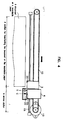
- the inkjet printhead 6 When a position detecting sensor 31 detects the inkjet printhead 6 during the printing operation, the inkjet printhead 6 is moved by a controller (not shown) to a position S in the service station 30. On the other hand, the inkjet printhead 6 is moved to an initial position C so that the nozzle 6a of the printhead is closed by a cap 32 for the ink to be prevented from being dried.
- the multi-functional apparatus receives a command for printing or scanning operation from a host computer, the carriage 20 is moved along the guide shaft 18 to an end of the guide shaft 18 so that the nozzle 6a of the inkjet printhead 6 is positioned at the position S. Then, the carriage 20 is reciprocally moved along the guide shaft 18 while the inkjet printhead 6 performs the printing operation.
- the carriage 20 When the printing operation is completed, the carriage 20 is moved along the guide shaft 18 to the service station. As shown in FIG. 4, when the position detecting sensor 31 detects the carriage 20, the controller controls the inkjet printhead 4 so that the nozzle 6a is engaged with the cap 32. At that time, the scanning module 3 is positioned near the paper transferring section.
- the carriage 20 having the scanning module 3 and the inkjet printhead 6 mounted thereon move reciprocally along a small length of the guide shaft.
- the multi-functional apparatus can be made to be small. That is, the scanning module 3 is mounted to be adjacent to the character recognising region and the printhead 6 is disposed to be at the side of the scanning module 3, allowing the width of the multi-functional apparatus to be reduced.
Landscapes
- Engineering & Computer Science (AREA)
- Multimedia (AREA)
- Signal Processing (AREA)
- Artificial Intelligence (AREA)
- Computer Vision & Pattern Recognition (AREA)
- Physics & Mathematics (AREA)
- General Physics & Mathematics (AREA)
- Theoretical Computer Science (AREA)
- Ink Jet (AREA)
- Facsimile Scanning Arrangements (AREA)
Applications Claiming Priority (2)
| Application Number | Priority Date | Filing Date | Title |
|---|---|---|---|
| KR7823997 | 1997-12-30 | ||
| KR1019970078239A KR100288694B1 (ko) | 1997-12-30 | 1997-12-30 | 소형 복합기 |
Publications (2)
| Publication Number | Publication Date |
|---|---|
| EP0930771A2 true EP0930771A2 (de) | 1999-07-21 |
| EP0930771A3 EP0930771A3 (de) | 2000-06-07 |
Family
ID=19529800
Family Applications (1)
| Application Number | Title | Priority Date | Filing Date |
|---|---|---|---|
| EP98310799A Ceased EP0930771A3 (de) | 1997-12-30 | 1998-12-30 | Kompaktes Multifunktionsgerät |
Country Status (3)
| Country | Link |
|---|---|
| US (1) | US6264384B1 (de) |
| EP (1) | EP0930771A3 (de) |
| KR (1) | KR100288694B1 (de) |
Cited By (1)
| Publication number | Priority date | Publication date | Assignee | Title |
|---|---|---|---|---|
| US7815304B2 (en) * | 2005-03-04 | 2010-10-19 | Samsung Electronics Co., Ltd. | Print medium stacking unit and image forming apparatus with the same |
Families Citing this family (8)
| Publication number | Priority date | Publication date | Assignee | Title |
|---|---|---|---|---|
| US6561606B1 (en) * | 1999-09-30 | 2003-05-13 | Canon Kabushiki Kaisha | Ink jet printing apparatus, image reading apparatus, ink jet printing method and image reading method |
| EP1158766A1 (de) * | 2000-05-24 | 2001-11-28 | Hewlett-Packard Company, A Delaware Corporation | Verfahren und Vorrichtung zur Auswahl von Objekten |
| US6592197B2 (en) * | 2001-07-31 | 2003-07-15 | Hewlett-Packard Development Company, L.P. | Printer device and method |
| KR100608007B1 (ko) * | 2004-09-22 | 2006-08-02 | 삼성전자주식회사 | 화상입출력장치 |
| KR100608008B1 (ko) * | 2004-09-25 | 2006-08-02 | 삼성전자주식회사 | 화상입출력장치 |
| EP1681845A3 (de) * | 2005-01-18 | 2006-10-18 | Samsung Electronics Co., Ltd. | Drucken und Abtasten von Information |
| ITTO20110261A1 (it) * | 2011-03-25 | 2012-09-26 | St Microelectronics Srl | "apparecchio scanner, procedimento e prodotto informatico relativi" |
| TWI505689B (zh) * | 2013-01-04 | 2015-10-21 | Microjet Technology Co Ltd | 適用於頁寬列印裝置之自動化列印校正方法 |
Citations (4)
| Publication number | Priority date | Publication date | Assignee | Title |
|---|---|---|---|---|
| EP0517396A1 (de) * | 1991-05-20 | 1992-12-09 | Xerox Corporation | Abtaster |
| EP0664640A2 (de) * | 1994-01-10 | 1995-07-26 | Fujitsu Limited | Einheit zum Lesen und Drucken von Bildern |
| JPH09109375A (ja) * | 1995-10-16 | 1997-04-28 | Alps Electric Co Ltd | インクジェットプリンタ |
| FR2748177A1 (fr) * | 1996-04-25 | 1997-10-31 | Girod Raoul | Tete mixte d'impression-lecture |
Family Cites Families (5)
| Publication number | Priority date | Publication date | Assignee | Title |
|---|---|---|---|---|
| US5049999A (en) * | 1990-07-02 | 1991-09-17 | Xerox Corporation | Compact multimode input and output scanner |
| JPH06343116A (ja) * | 1993-03-26 | 1994-12-13 | Canon Inc | 画像記録装置 |
| KR0165206B1 (ko) * | 1995-10-18 | 1999-05-01 | 김광호 | 홈위치 감지장치 및 방법 |
| KR0150298B1 (ko) * | 1995-12-12 | 1998-12-01 | 김광호 | 잉크젯 프린터의 캐리지 위치 이탈 감지와 보정 방법 |
| KR200151933Y1 (ko) * | 1996-04-08 | 1999-07-15 | 윤종용 | 잉크젯프린터의 서어비스 스테이션장치 |
-
1997
- 1997-12-30 KR KR1019970078239A patent/KR100288694B1/ko not_active IP Right Cessation
-
1998
- 1998-12-30 US US09/222,823 patent/US6264384B1/en not_active Expired - Fee Related
- 1998-12-30 EP EP98310799A patent/EP0930771A3/de not_active Ceased
Patent Citations (4)
| Publication number | Priority date | Publication date | Assignee | Title |
|---|---|---|---|---|
| EP0517396A1 (de) * | 1991-05-20 | 1992-12-09 | Xerox Corporation | Abtaster |
| EP0664640A2 (de) * | 1994-01-10 | 1995-07-26 | Fujitsu Limited | Einheit zum Lesen und Drucken von Bildern |
| JPH09109375A (ja) * | 1995-10-16 | 1997-04-28 | Alps Electric Co Ltd | インクジェットプリンタ |
| FR2748177A1 (fr) * | 1996-04-25 | 1997-10-31 | Girod Raoul | Tete mixte d'impression-lecture |
Cited By (1)
| Publication number | Priority date | Publication date | Assignee | Title |
|---|---|---|---|---|
| US7815304B2 (en) * | 2005-03-04 | 2010-10-19 | Samsung Electronics Co., Ltd. | Print medium stacking unit and image forming apparatus with the same |
Also Published As
| Publication number | Publication date |
|---|---|
| KR100288694B1 (ko) | 2001-05-02 |
| KR19990058152A (ko) | 1999-07-15 |
| EP0930771A3 (de) | 2000-06-07 |
| US6264384B1 (en) | 2001-07-24 |
Similar Documents
| Publication | Publication Date | Title |
|---|---|---|
| US5790915A (en) | Plane registration for monochrome and color printing systems | |
| EP2346235B1 (de) | Optische Lesevorrichtung, Steuerungsverfahren für eine optische Lesevorrichtung und Programm | |
| EP0930771A2 (de) | Kompaktes Multifunktionsgerät | |
| KR101739595B1 (ko) | 광학 판독 장치, 광학 판독 장치의 제어 방법 및 컴퓨터가 판독 가능한 기록 매체 | |
| JP2960930B2 (ja) | スキャニング機能および印刷機能を有する複合機,複合機のスキャニングおよび印刷方法 | |
| KR100223006B1 (ko) | 셔틀방식 복합기의 인쇄오차 보정방법 | |
| JP3297431B2 (ja) | 画像処理装置 | |
| JP3457179B2 (ja) | 画像読取方法および画像読取装置 | |
| KR100708136B1 (ko) | 화상입출력장치 및 화상입출력방법 | |
| US6108456A (en) | Image processing system | |
| KR100218002B1 (ko) | 셔틀 스캐너 방식의 복합기에서 프린팅 영역 판별 방법 | |
| KR19990027149A (ko) | 스캐너의 블록간 화질현차 보상방법 | |
| US5793499A (en) | Fax status stamp on back of document | |
| KR100234431B1 (ko) | 셔틀 스캐너 방식 복합기의 스캔 영역 감지 장치 및 감지 방법 | |
| JP3605809B2 (ja) | プリンタ | |
| KR100477628B1 (ko) | 셔틀방식의프린터,스캐너,팩스및복사기능을갖는복합기 | |
| KR19990000354A (ko) | 작은용지의 퀵(Quick)스캐닝 장치 및 방법 | |
| JP3549304B2 (ja) | 記録装置 | |
| KR19980084052A (ko) | 셔틀 스캐너 방식의 복합기에서 팩스 송신시 비 규격 원고의 스캐닝 방법 | |
| KR100213907B1 (ko) | 프린터의 독취 장치 및 그 제어 방법 | |
| KR100238053B1 (ko) | 복합기의 스캐닝/인쇄 이중처리 방법 및 장치 | |
| KR100202269B1 (ko) | 상형성체와 데이터독취기가 일체화된 복합장치 | |
| JP3347379B2 (ja) | 画像処理方法及び装置 | |
| KR100277772B1 (ko) | 컬러 카트리지를 이용한 팩스 데이터의 프린팅 방법 | |
| KR100229509B1 (ko) | 셔틀 스캐너 방식 복합기에서 용지 선단 검출 및 정렬방법 |
Legal Events
| Date | Code | Title | Description |
|---|---|---|---|
| PUAI | Public reference made under article 153(3) epc to a published international application that has entered the european phase |
Free format text: ORIGINAL CODE: 0009012 |
|
| 17P | Request for examination filed |
Effective date: 19990119 |
|
| AK | Designated contracting states |
Kind code of ref document: A2 Designated state(s): DE FR GB IT |
|
| AX | Request for extension of the european patent |
Free format text: AL;LT;LV;MK;RO;SI |
|
| PUAL | Search report despatched |
Free format text: ORIGINAL CODE: 0009013 |
|
| AK | Designated contracting states |
Kind code of ref document: A3 Designated state(s): AT BE CH CY DE DK ES FI FR GB GR IE IT LI LU MC NL PT SE |
|
| AX | Request for extension of the european patent |
Free format text: AL;LT;LV;MK;RO;SI |
|
| AKX | Designation fees paid |
Free format text: DE FR GB IT |
|
| STAA | Information on the status of an ep patent application or granted ep patent |
Free format text: STATUS: THE APPLICATION HAS BEEN REFUSED |
|
| 18R | Application refused |
Effective date: 20061118 |