EP0930501A2 - Procédé et capteur pour mesurer la concentration de NOx - Google Patents
Procédé et capteur pour mesurer la concentration de NOx Download PDFInfo
- Publication number
- EP0930501A2 EP0930501A2 EP99101007A EP99101007A EP0930501A2 EP 0930501 A2 EP0930501 A2 EP 0930501A2 EP 99101007 A EP99101007 A EP 99101007A EP 99101007 A EP99101007 A EP 99101007A EP 0930501 A2 EP0930501 A2 EP 0930501A2
- Authority
- EP
- European Patent Office
- Prior art keywords
- concentration
- oxygen
- space
- nox
- pumping
- Prior art date
- Legal status (The legal status is an assumption and is not a legal conclusion. Google has not performed a legal analysis and makes no representation as to the accuracy of the status listed.)
- Granted
Links
Images


Classifications
-
- G—PHYSICS
- G01—MEASURING; TESTING
- G01N—INVESTIGATING OR ANALYSING MATERIALS BY DETERMINING THEIR CHEMICAL OR PHYSICAL PROPERTIES
- G01N27/00—Investigating or analysing materials by the use of electric, electrochemical, or magnetic means
- G01N27/26—Investigating or analysing materials by the use of electric, electrochemical, or magnetic means by investigating electrochemical variables; by using electrolysis or electrophoresis
- G01N27/416—Systems
- G01N27/417—Systems using cells, i.e. more than one cell and probes with solid electrolytes
Definitions
- the present invention relates to a method for measuring the concentration of NOx in a gas to be measured as well as to an NOx concentration sensor and to an apparatus for measuring NOx concentration.
- the conventional method includes the steps of: pumping out oxygen from one measurement space by means of a first pumping cell to an extent so as not to cause dissociation of NO; causing NO to completely dissociate in the other measurement space by means of a second pumping cell; and determining NOx concentration based on a pumping current induced by oxygen ions generated by dissociation of NO.
- Japanese Patent Application Laid-Open ( Kokai ) No. 2-1543 proposes a method for measuring the concentration of NOx, typically nitrogen monoxide (NO), contained in exhaust gas, using an NOx concentration sensor composed of two measurement spaces, each of which is equipped with a pumping cell.
- NOx nitrogen monoxide
- the method includes the steps of: pumping out only oxygen from one measurement space to an extent so as not to cause dissociation of NO; measuring a current, Ip1, flowing through a pumping cell (hereinafter referred to as a pumping current) associated with the measurement space; causing O 2 and NO to dissociate in the second measurement space; pumping out, from the second measurement space, oxygen generated by dissociation of O 2 and NO; measuring a pumping current, Ip2, flowing through the second pumping cell; and determining NOx concentration based on the difference between the pumping currents (Ip2 - Ip1).
- Japanese Patent Application Laid-Open ( Kokai ) No. 2 122255 proposes a method for measuring the concentration of a certain gas component contained in a mixed gas which contains an oxygen compound other than the gas component to be measured.
- the method includes the steps of: causing dissociation of the oxygen compound having a dissociation voltage lower than that of the gas component to be measured, by applying a certain fixed voltage (which does not cause dissociation of the gas component to be measured) to a first pumping cell; pumping out oxygen generated by dissociation of the oxygen compound; causing dissociation of the gas component to be measured by applying a certain voltage to a second pumping cell; detecting the amount of oxygen generated by dissociation of the gas component to be measured in terms of a second pumping current, Ip2; and determining the concentration of the gas component to be measured based on the second pumping current Ip2.
- Japanese Patent Application Laid-Open ( Kokai ) No. 8 271476 proposes an improvement in the above-described method for measuring NOx concentration.
- the method includes the steps of: eliminating excess oxygen from a first space by controlling the amount of oxygen contained in the first space so as not to substantially affect the measurement of NOx concentration and so as not to cause substantial dissociation of NO; causing dissociation of NO in a second space; and determining NOx concentration based on a pumping current, Ip2, induced by oxygen generated by dissociation of NO.
- the above-described methods have been developed in order to measure the concentration of NOx, for example, in an automobile exhaust gas.
- a need for measuring the concentration of NOx in a catalytically purified exhaust gas in order to verify the purification performance of an exhaust gas purification catalyst.
- the accuracy required for measuring NOx concentration is not greater than ⁇ several tens of ppm with respect to several hundreds of ppm in NOx concentration.
- the above-described methods fail to sufficiently satisfy this accuracy requirement and thus there is a need for further improvement.
- the method for measuring NOx concentration using the aforementioned NOx concentration sensor significantly depends on oxygen concentration and temperature, and therefore it is difficult to accurately measure the NOx concentration.
- the present invention relates to an NOx concentration sensor for measuring the concentration of NOx in exhaust gas emitted from an internal combustion engine used in transportation equipment such as an automobile, ship, or an airplane, or industrial equipment such as a boiler, as well as to an apparatus and a method for measuring NOx concentration.
- the first pumping current Ip1 is relatively strong.
- the differential pumping current (Ip2 - Ip1) is considerably influenced by variation of the first pumping current Ip1. Therefore, due to variation among sensors and temperature, measurement accuracy is impaired.
- the present invention has been achieved in view of the above problems of the prior art. It is therefore the object of the present invention to provide a method for measuring the concentration of NOx contained in a measurement gas as well as to provide an NOx concentration sensor and an apparatus for measuring NOx concentration thereby overcoming the drawbacks of the prior art.
- the method and the devices according to the invention shall be capable of accurately measuring NOx concentration.
- the present invention provides a method for measuring the concentration of NOx in a measurement gas such as exhaust gas emitted from combustion equipment or an internal combustion engine, as well as an NOx concentration sensor and an apparatus for measuring NOx concentration.
- the present invention relates to an NOx concentration sensor for measuring the concentration of NOx in exhaust gas emitted from an internal combustion engine used in transportation equipment such as an automobile, ship, or an airplane, or industrial equipment such as a boiler, as well as to an apparatus and a method for measuring NOx concentration.
- Nitrogen monoxide (NO) is dominant among NOx contained, for example, in an automobile exhaust gas.
- NOx species other than NO that is, the content of N 2 O and NO 2 . Therefore, the following description relates to the measurement of NO concentration.
- NOx concentration substantially means "NO concentration”.
- a two-serial-space NOx concentration sensor comprising a measurement gas space (ambient atmosphere to be measured) in series communication with a first internal space a second internal space.
- a measurement gas is introduced from the measurement gas space into the first space and then into the second space.
- the NOx concentration sensor by activating a first pumping cell, a portion of oxygen (O 2 ) and nitrogen monoxide (NO) contained in the first space dissociates to generate oxygen ions (O 2- ). The thus-generated oxygen ions are transferred (pumped out) into the measurement gas space. By contrast, oxygen can also be pumped into the first space from the measurement gas space.
- a second pumping cell residual O 2 and NO contained in gas diffusing within the second space dissociate to generate oxygen ions, which are also removed by pumping.
- the first pumping cell and the second pumping cell may each comprise a solid electrolyte substrate and a pair of porous electrodes disposed on opposite sides or a single side of the substrate. By applying a predetermined voltage between the porous electrodes, oxygen can be transferred from one of the porous electrodes to the other.
- a first mode of a first aspect of the present invention provides a method for measuring NOx concentration using a two-serial-space NOx concentration sensor.
- the sensor includes a first pumping cell and a second pumping cell each comprising a solid electrolyte.
- a measurement gas space, a first space, and a second space communicate in series with each other.
- the method comprises the steps of: pumping out oxygen from the first space into, for example, the measurement gas space, or pumping oxygen into the first space from, for example, the measurement gas space by action of the first pumping cell so that the oxygen concentration in the vicinity of a gas inlet of the second space becomes such that a portion of NO in the first space dissociates; dissociating residual NO and O 2 in gas introduced into the second space from the first space by action of the second pumping cell; pumping out oxygen ions generated by dissociation of NO and O 2 from the second space by action of the second pumping cell; and determining the concentration of NOx in the measurement gas based on signals (for example, pumping currents) issued from the first and second pumping cells.
- signals for example, pumping currents
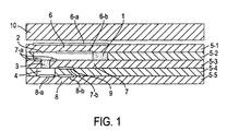
- FIG. 1 shows an NOx concentration sensor in accordance with the present invention.
- the measurement gas is introduced into the first space from the measurement gas space.
- the first pumping cell is operated so that the oxygen concentration in the vicinity of the gas inlet of the second space becomes such that a portion of NO in the first space dissociates.
- the degree of dissociation of NO in the first space is represented by the dissociation percentage ⁇ (%).
- the oxygen concentration of the measurement gas introduced into the second space from the first space is decreased such that a portion of NO in the first space dissociates. Accordingly, the magnitude of the Ip2offset signal associated with oxygen concentration and issuing from the second pumping cell becomes low. Furthermore, the extent of variation in Ip2offset becomes small. Thus, Ip2offset less strongly affects the signal Ip2 - Ip2offset, associated with the quantity of NO dissociated and issuing from the second pumping cell, to thereby provide improved accuracy in measuring NO concentration.
- NO in the measurement gas dissociates within the first space to a predetermined degree (a predetermined dissociation percentage ⁇ ). Furthermore, residual NO dissociates within the second space. Accordingly, as described below in relation to an eighth mode of the first aspect of the invention, the concentration of NO in the measurement gas can be determined based on the NO dissociation percentage in the first space and the quantity of NO dissociated in the second space.
- the concentration of NO in the measurement gas can be determined based on a signal (for example, the first pumping current) associated with the dissociation of NO within the first space and issuing from the first pumping cell and a signal (for example, the second pumping current) associated with the dissociation of NO within the second space and issuing from the second pumping cell.
- a signal for example, the first pumping current
- the second pumping current associated with the dissociation of NO within the second space and issuing from the second pumping cell.
- the first space of the NOx concentration sensor preferably communicates with the measurement gas space via a first diffusion resistance element, and the first space and the second space preferably communicate via a second diffusion resistance element.
- the measurement gas space and the first space communicate via the first diffusion resistance element.
- the measurement gas space is diffusion-controlled by the first diffusion resistance element.
- the measurement gas introduced into the first space from the measurement gas space is diffusion-controlled by the first diffusion resistance element.
- the quantities of oxygen and NO introduced into the first space are limited. Accordingly, even when a voltage is applied between the electrodes of the first pumping cell, the first pumping current does not flow in excess of a certain limiting value.
- the first space and the second space communicate via the second diffusion resistance element. Accordingly, the measurement gas introduced into the second space is diffusion-controlled by the second diffusion resistance element. Through this diffusion control, the quantities of oxygen and NO introduced into the first space are limited. Accordingly, even when a voltage is applied between the electrodes of the second pumping cell, the second pumping current does not flow in excess of a certain limiting value.
- the above-mentioned sensor having diffusion resistance elements is called a limit-current-type sensor and can obtain the concentration of oxygen or NO contained in a measurement gas stably and accurately. This is because a limit current can be obtained according to the concentration of oxygen or NO in the measurement gas.
- an oxygen-concentration-measuring cell for detecting the concentration of oxygen in gas introduced into the second space of the NOx concentration sensor is preferably disposed in the vicinity of the gas inlet of the second space.
- the third mode of the first aspect of the invention provides a method for detecting oxygen concentration in the vicinity of the gas inlet of the second space.
- the oxygen-concentration-measuring cell is disposed in the vicinity of the gas inlet of the second space.
- the oxygen concentration of the measurement gas introduced into the second space can be accurately controlled.
- the oxygen-concentration-measuring cell can assume the form of an oxygen concentration cell, which generates an electromotive force according to an oxygen concentration differential.
- the oxygen-concentration-measuring cell may be composed of, for example, a solid electrolyte substrate and a pair of porous electrodes disposed on opposite sides of the substrate. In this case, one of the electrodes is disposed so as to contact the measurement gas, whereas the other electrode is disposed so as to contact a reference gas.
- Vsm electromotive force
- the first pumping cell is preferably controlled based on a signal issuing from the oxygen-concentration-measuring cell for detecting oxygen concentration in the vicinity of the gas inlet of the second space of the NOx concentration sensor.
- the fourth mode of the first aspect of the invention provides a method for controlling the first pumping cell. Specifically, the first pumping cell is controlled based on a signal issuing from the oxygen-concentration-measuring cell.
- a signal for example, voltage Vsm
- Vsm voltage
- the first pumping cell is controlled such that Vsm approaches a predetermined target value, namely, such that Vsm achieves a target voltage Vs, thereby controlling the quantity of oxygen that is pumped out from or pumped into the first space.
- oxygen concentration in the vicinity of the gas inlet of the second space can be controlled to a desired value, which corresponds to the target voltage Vs.
- a target value of the oxygen concentration in the vicinity of the gas inlet of the second space is preferably set to a value not higher than 2 x 10 -7 atm in terms of oxygen partial pressure.
- the fifth mode of the first aspect of the invention specifies a target value of the oxygen concentration in the vicinity of the gas inlet of the second space.
- the target oxygen concentration in the vicinity of the gas inlet of the second space is set to a partial pressure of oxygen of not higher than 2 x 10 -7 atm, but higher than 2 x 10 -10 atm , which is a sufficiently low level to cause partial dissociation of NO in the first space.
- the oxygen concentration of the second space is sufficiently decreased, thereby decreasing an offset component of the second pumping current and thus enabling accurate measurement of NO concentration.
- the above-mentioned target oxygen concentration is more preferably set to a value of from 2 x10 -8 to 2 x 10 -9 atm in terms of an oxygen partial pressure.
- the NO dissociation percentage in the first space preferably is not lower than 0.5%.
- the sixth mode of the first aspect of the invention specifies, in terms of the degree of dissociation of NO (dissociation percentage ⁇ ), that the oxygen concentration in the vicinity of the gas inlet of the second space is decreased such that a portion of NO in the first space dissociates.
- oxygen concentration in the vicinity of the gas inlet of the second space is decreased such that the NO dissociation percentage in the first space becomes not lower than 0.5%.
- the oxygen concentration of the second space is decreased to thereby improve accuracy in measuring NO concentration.
- the NO dissociation percentage in the first space preferably is 1% to 50%.
- the seventh mode of the first aspect of the invention specifies a more preferable dissociation percentage range. Specifically, when the NO dissociation percentage is not lower than 1%, as described above in relation to the first mode of the first aspect of the invention, the oxygen concentration of the second space is further decreased to thereby improve accuracy in measuring NO concentration.
- the NO dissociation percentage When the NO dissociation percentage is in excess of 50%, an offset component of the second pumping current is limited to a low level; however, the NO dissociation percentage varies greatly with a variation in the oxygen concentration and temperature of the measurement gas space. Thus, measurement accuracy deteriorates greatly where environmental conditions vary significantly. More preferably, the NO dissociation percentage is 2% to 20%.
- the concentration of NOx in the measurement gas is preferably calculated based on signals corresponding to the NO dissociation percentage in the first space and the quantity of NO dissociated in the second space.
- the eighth mode of the first aspect of the invention specifies a method for determining the concentration of NOx in the measurement gas.
- the NOx concentration is calculated based on a signal issuing from the first pumping cell (for example, the first pumping current) and a signal issuing from the second pumping cell (for example, the second pumping current).
- the operation of the first pumping cell causes NO in the first space to dissociate to a certain degree (at a certain dissociation percentage ⁇ ). Accordingly, a signal issuing from the first pumping cell corresponds to the oxygen concentration of the measurement gas and the NO dissociation percentage in the first space. Also, operation of the second pumping cell causes residual NO, namely, NO which has not dissociated in the first space and which has been introduced into the second space, to dissociate in the second space. Accordingly, a signal issuing from the second pumping cell corresponds to the quantity of NO dissociated in the second space and the quantity of oxygen introduced into the second space.
- the effect of oxygen concentration must be eliminated.
- the second pumping current includes an offset current induced by oxygen concentration
- the offset current is preferably eliminated, as described below.
- the measurement gas is introduced into the first space to form a new gas which then enters the second space via a gas diffusion resistance that separates the first and second space.
- the operation of the first pumping cell dissociates O 2 to a certain oxygen partial pressure level and also causes NO in the first space to partially dissociate to a certain degree (at a certain dissociation percentage ⁇ ).
- Operation of the second pumping cell causes the residual NO, namely, NO which has not dissociated in the first space and which has been introduced into the second space, to dissociate in the second space. Accordingly, NO concentration can be detected based on the state of dissociation of NO in the first and second spaces.
- the offset current Ip2offset which corresponds to the quantity of O 2 dissociated in the second space, is desirably eliminated from the second pumping current Ip2.
- the resulting difference, Ip2 - Ip2offset corresponds to the quantity of NO dissociated in the second space.
- the NO concentration of the measurement gas introduced into the second space can be represented by "1- ⁇ /100.” If all of the NO introduced into the second space dissociates, then a current corresponding to the NO concentration of the measurement gas is represented by "(Ip2 - Ip2offset) / (1 - ⁇ /100)."
- the offset current Ip2offset appearing in the equation A1 is obtained from the first pumping current Ip1.
- the Ip2offset can be determined by a relation (or map) pre-measured or rather predetermined with the electromotive force cell voltage Vs that represents an oxygen partial pressure level at an inlet of the second passage (or rather at an outlet of the first passage), and further because the voltage Vs can also act as a parameter functioning between the first pumping current Ip1 and the oxygen concentration level of a measurement gas of interest entering the first passage.
- the method for measuring NOx concentration as described in any of the first through eighth modes of the first aspect of the invention and, in particular, as described in the ninth mode of the first aspect of the invention employs an NOx concentration sensor in which the first pumping cell is controlled such that a signal issuing from the oxygen-concentration-measuring cell for detecting oxygen concentration in the vicinity of the gas inlet of the second space assumes a target value.
- the method preferably comprises the steps of: calculating the concentration of oxygen in the measurement gas using a map of a previously measured relationship between current flowing through the first pumping cell and the concentration of oxygen in the measurement gas while taking the target value as a parameter; and calculating Ip2offset using a map of a previously measured relationship between Ip2offset and the concentration of oxygen in the measurement gas while taking the target value as a parameter.
- the tenth mode of the first aspect of the invention provides a more specific method according to the ninth mode of the first aspect of the invention.
- a map showing the relationship among the target value (target voltage Vs for the oxygen-concentration-measuring cell), current flowing through the first pumping cell (the first pumping current Ip1), and the oxygen concentration of the measurement gas is experimentally prepared in advance, for example, as shown in FIG. 2.
- the concentration of oxygen in the measurement gas is obtained using this map, and is based on a measured value of Ip1 and a predetermined target value of Vs.
- a map showing the relationship among the target value (Vs), the offset current Ip2offset, and the oxygen concentration of the measurement gas is experimentally prepared in advance.
- the offset current Ip2offset is obtained using this map, and is based on a predetermined target value of Vs and the above-obtained oxygen concentration.
- the offset current Ip2offset for use in the expression A1 is thus obtained.
- the maps shown in FIGS. 2 and 3 are in the form of a graph representing the relationship between oxygen concentration and a pumping current, but are not limited thereto. Alternatively, the maps may assume, for example, the form of an ordinary matrix table.
- the method for measuring NOx concentration as described in any one of the first through eighth modes of the first aspect of the invention and, in particular, as described in the ninth or the tenth mode of the first aspect of the invention employs an NOx concentration sensor in which the first pumping cell is preferably controlled such that a signal issuing from the oxygen-concentration-measuring cell for detecting oxygen concentration in the vicinity of the gas inlet of the second space assumes a target value.
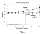
- the method advantageously comprises the steps of: calculating the concentration of oxygen in the measurement gas using a map of a previously measured relationship between current flowing through the first pumping cell and the concentration of oxygen in the measurement gas while taking the target value as a parameter; and calculating A/(1 - ⁇ /100) (hereinafter referred to as gain) using a map of a previously measured relationship between gain and the concentration of oxygen in the measurement gas while taking the target value as a parameter.
- the eleventh mode of the first aspect of the invention provides a more specific method according to the ninth mode of the first aspect of the invention.
- the concentration of oxygen in the measurement gas is calculated based on the first pumping current Ip1 and by using, for example, the map shown in FIG. 2.
- a map is experimentally prepared in advance showing the relationship among the target oxygen concentration (the target voltage Vs for the oxygen-concentration-measuring cell), gain and the concentration of oxygen in the measurement gas. The gain is obtained using this map, and is based on Vs and the above-obtained oxygen concentration.
- the map shown in FIG. 4 may also assume the form of an ordinary matrix table as in the case of other similar maps.
- the gain is thus obtained.
- the offset current Ip2offset is obtained according to the aforementioned tenth mode of the first aspect of the invention.
- the second pumping current Ip2 is obtained by actual measurement. By substituting these values into the expression A1, the NO concentration can be obtained, or the substantial NOx concentration of the measurement gas can be obtained.
- an NOx concentration sensor which is a two-serial-space-type NOx concentration sensor comprising a first space, a second space, a first diffusion resistance element and a second diffusion resistance element.
- the first space is partially defined by a first pumping cell and an oxygen-concentration-measuring cell, each comprising a solid electrolyte layer and a pair of electrodes.
- the second space is partially defined by a second pumping cell comprising a solid electrolyte layer and a pair of electrodes.
- the first diffusion resistance element establishes communication between the first space and a measurement gas space.
- the second diffusion resistance element establishes communication between the first space and the second space.
- the oxygen-concentration-measuring cell is disposed in the vicinity of the second diffusion resistance element, and the sensor further comprises a measuring section (which can comprise a circuit) for measuring a first pumping current flowing through the first pumping cell, a measuring section (which can comprise a circuit) for measuring a second pumping current flowing through the second pumping cell, and a calculation section (which can comprise a circuit and/or a microprocessor and associated memory) for calculating the concentration of NOx in the measurement gas based on the first pumping current and the second pumping current.
- a measuring section which can comprise a circuit
- a measuring section which can comprise a circuit
- a calculation section which can comprise a circuit and/or a microprocessor and associated memory
- the first mode of the second aspect of the invention specifies the structure of the NOx concentration sensor.
- oxygen concentration in the vicinity of the gas inlet of the second space is measured by the oxygen-concentration-measuring cell disposed in the vicinity of the second diffusion resistance element.
- the first pumping cell is operated such that the thus-measured oxygen concentration assumes a predetermined value (namely, such that a portion of NO in the first space dissociates).
- the first pumping current and the second pumping current are measured. Based on the measured currents, the concentration of NO in the measurement gas is determined, as described in detail below.
- oxygen is preferably pumped out from or pumped into the first space by means of the first pumping cell so that the oxygen concentration in the vicinity of the gas inlet of the second space becomes such that a portion of the NO contained in the first space dissociates.
- the second mode of the second aspect of the invention specifies the function of the first pumping cell.
- the first pumping cell is activated so as to pump out oxygen from or pump oxygen into the first space.
- the oxygen concentration in the vicinity of the gas inlet of the second space is regulated such that a portion of the NO contained in the first space dissociates.
- the third mode of the second aspect of the invention provides an NOx concentration sensor for implementing the method of the ninth mode of the first aspect of the invention.
- the expression A1 has the same meaning as in the ninth mode of the first aspect of the invention.
- the quantity "Ip2 - Ip2offset" corresponds to a signal which, in turn, corresponds to the quantity of NO dissociated in the second space
- a current corresponding to the concentration of NO in the measurement gas is represented by (Ip2 - Ip2offset)/(1 - ⁇ /100). Accordingly, by multiplying the current (Ip2 - Ip2offset) /(1- ⁇ /100) by the conversion coefficient A, the concentration of NO in the measurement gas can be obtained.
- the NOx concentration sensor as described in the third mode of the second aspect of the invention in which the first pumping cell is controlled such that a signal issuing from the oxygen-concentration-measuring cell for detecting oxygen concentration in the vicinity of the gas inlet of the second space assumes a target value, further preferably comprises an oxygen concentration calculation section (which may comprise a circuit and/or a microprocessor and associated memory) and an Ip2offset calculation section (which may comprise a circuit and/or a microprocessor and associated memory) .
- an oxygen concentration calculation section which may comprise a circuit and/or a microprocessor and associated memory
- Ip2offset calculation section which may comprise a circuit and/or a microprocessor and associated memory
- the oxygen concentration calculation section calculates the concentration of oxygen in the measurement gas using a map which shows a previously measured relationship between current flowing through the first pumping cell and the concentration of oxygen in the measurement gas while taking the target value as a parameter, that is, for a certain target value.
- the Ip2offset calculation section calculates Ip2offset using a map which shows the previously measured relationship between Ip2offset and the concentration of oxygen in the measurement gas while taking the target value as a map parameter.
- the fourth mode of the second aspect of the invention provides an NOx concentration sensor for implementing the method of the tenth mode of the first aspect of the invention.
- the concentration of oxygen in the measurement gas is obtained using the map of FIG. 2.
- the offset current Ip2offset can be obtained using the map of FIG. 3.
- the NOx concentration sensor as described in the third or fourth mode of the second aspect of the invention in which the first pumping cell is controlled such that a signal issuing from the oxygen-concentration-measuring cell for detecting oxygen concentration in the vicinity of the gas inlet of the second space assumes a target value, further preferably comprises an oxygen concentration calculation section and, advantageously, a gain calculation section (which may comprise a circuit and/or a microprocessor and associated memory).
- the oxygen concentration calculation section calculates the concentration of oxygen contained in the measurement gas using a map which shows a previously measured relationship between current flowing through the first pumping cell and the concentration of oxygen in the measurement gas while taking the target value as a parameter.
- the gain calculation section calculates A/(1 - ⁇ /100) (gain) using a map which shows a previously measured relationship between the gain and the concentration of oxygen in the measurement gas while taking the target value as a parameter.
- the fifth mode of the second aspect of the invention provides an NOx concentration sensor for implementing the method of the eleventh mode of the first aspect of the invention.
- the concentration of oxygen in the measurement gas is obtained using the map of FIG. 2.
- the gain can be obtained using the map of FIG. 4.
- the senor is preferably controlled to a predetermined temperature of 550 to 900°C by disposing one or more heaters on a single side or on opposite sides of the sensor.
- the NO dissociation percentage in the first space varies with the temperature of the sensor (element temperature). Therefore, the sensor is preferably used within a temperature range such that the NO dissociation percentage does not vary greatly. In another aspect for providing accurate NOx measurement, it is important to maintain a temperature drift of the sensor within ⁇ 5°C, preferably ⁇ 2.5° C, more preferably ⁇ 1°C. This is because the sensor temperature drift varies the NO dissociation percentage and in turn affects the measurement accuracy.
- the dissociation of NO and oxygen means the separation of NO and oxygen into simpler constituents.
- nitrogen monoxide (NO) dissociates into nitrogen (molecular nitrogen N 2 ) and oxygen (molecular oxygen O 2 ), and oxygen (molecular oxygen O 2 ) dissociates into oxygen ions (O 2- ).
- NO nitrogen monoxide
- O 2 oxygen
- O 2- oxygen ions
- a first mode of a third aspect of the present invention has the following features.
- a measurement gas including O 2 and NOx diffuses into a first passage, which faces a first pumping cell, and then diffuses into a second passage, which faces a second pumping cell.
- the first pumping cell causes a portion of O 2 and NO contained in the gas which has diffused into the first passage to dissociate, thereby controlling the concentration of oxygen in the gas contacting the second pumping cell to as low a level as possible.
- the second pumping cell causes residual NO contained in the gas which has diffused into the second passage to dissociate.
- the preferable range of the oxygen concentration of the gas detected at the inlet of the second passage, said gas then contacting with the second pump cell electrode is from 2 x 10 -7 to 2 x 10 -10 atm and more preferably from 2 x 10 -8 to 2 x 10 -9 atm defined by oxygen partial pressure, according to the invention.
- the range is calculated from the oxygen concentration cell voltage Vs, based on the known Nernst equation. In this range of the oxygen concentration, the improved accuracy of NOx measurement is attained because of a decomposition rate or dissociation percentage ⁇ of NO in the first passage where the first pumping cell is located can become constantly stable even if a substantial decomposition of NO occurs in the first passage.
- the Vsm value measured at the oxygen concentration detection electrode of the cell corresponding to the above oxygen concentration range is from 300 mV to 450 mV.
- the oxygen concentration cell has the oxygen reference electrode communicating with a self-made oxygen reference atmosphere having about 2 x 10 -0 atm. (as the case for the embodiment later explained), the corresponding Vsm is from 350 mV to 500 mV, measuring about 50 mV higher than the above range.
- a second mode of the third aspect of the present invention preferably includes means for correcting the measurement of NOx concentration to take into account a variation in the NO dissociation percentage in the first passage with a change in the concentration of oxygen in the measurement gas.
- the term ⁇ Ip2 (Ip2 - Ip2offset) is multiplied by a predetermined coefficient, which is a function of the NO dissociation percentage in the first passage.
- the measurement of NOx concentration can be further corrected for other factors by multiplying the term ⁇ Ip2 by another coefficient.
- the coefficient is experimentally obtained in advance and is selected according to Ip1 and/or Ip2, thereby further improving accuracy in measuring NOx concentration.
- a third mode of the third aspect of the present invention preferably includes means for correcting the measurement of NOx concentration to take into account a variation in the ratio between the concentration of NOx in the measurement gas and the concentration of NOx in the gas diffusing into the second passage caused by control of oxygen concentration by said first pumping cell.
- a fourth mode of the third aspect of the present invention preferably includes means for correcting the measurement of NOx concentration to take into account a variation in the ratio between the concentration of NOx in the measurement gas and the concentration of NOx in the gas diffusing into the second passage with a change in NO dissociation percentage in the first passage.
- a first mode of a fourth aspect of the present invention provides an NOx concentration sensor comprising a first passage, a second passage, an oxygen-concentration-measuring cell, a first pumping cell and a second pumping cell.
- a measurement gas diffuses into the first passage via a first diffusion resistance element.
- O 2 and NO are partially dissociated.
- Gas leaving the first passage diffuses into the second passage via a second diffusion resistance element facing a downstream end portion of the first passage.
- residual NO and O 2 in the gas introduced from the first passage are dissociated.
- the oxygen-concentration-measuring cell has an electrode which is disposed downstream of the first passage and on the inlet side of or facing the second diffusion resistance element.
- the oxygen-concentration-measuring cell measures the oxygen partial pressure by voltage developed across the oxygen concentration detection electrodes as described, for example, in U.S. Patent 4,272,329 incorporated herein by reference.
- the first pumping cell has an electrode facing the first passage. By applying a voltage to the electrode of the first pumping cell based on the electromotive force output from the oxygen-concentration-measuring cell, the first pumping cell causes a portion of O 2 and NO in the first passage to dissociate. A current (first pumping current) induced by oxygen ions generated by dissociation of O 2 and NO flows through the first pumping cell.
- the second pumping cell has an electrode facing the second passage.
- the second pumping cell By applying a voltage to the electrode of the second pumping cell, the second pumping cell causes residual O 2 and NO contained in the gas which has diffused into the second passage to dissociate.
- the concentration of NOx in the measurement gas is preferably obtained based on the first pumping current flowing through the first pumping cell and the second pumping current flowing through the second pumping cell.
- the first pumping current includes a current component induced by oxygen ions generated by the dissociation of NO in the first passage.
- the second pumping current includes a current component induced by oxygen ions generated by the dissociation of NO in the second passage.
- the electrode of the first pumping cell preferably extends along a gas flow within the first passage and on a solid electrolyte layer which constitutes the first pumping cell.
- the electrode of the oxygen-concentration-measuring cell is preferably formed on a solid electrolyte layer which constitutes the oxygen-concentration-measuring cell, in such manner as to be located downstream of the first passage and in the vicinity of an inlet to or facing the second diffusion resistance element.
- a first mode of a fifth aspect of the present invention has the following features.
- a measurement gas including O 2 and NOx diffuses into a first passage.
- a portion of the O 2 and NO in the gas which has diffused into the first passage is dissociated so as to control the concentration of oxygen in the gas diffusing into the second passage to as low a level as possible.
- Residual NO and O 2 contained in the gas which has diffused into the second passage are dissociated.
- the concentration of NOx in the measurement gas is obtained based on a first pumping current, which is induced by oxygen ions generated by the dissociation of O 2 and NO within the first passage, and a second pumping current, which is induced by oxygen ions generated by the dissociation of NO and O 2 within the second passage.
- the concentration of NOx in the measurement gas is preferably obtained based on the NO dissociation percentage in the first passage.
- the concentration of NOx in the measurement gas is advantageously obtained based on the NO dissociation percentage in the first passage and the rate of variation in NO concentration due to control of the concentration of oxygen in the gas diffusing into the second passage causing a variation in the ratio between the concentration of NO in the measurement gas and the concentration of NO in the gas diffusing into the second passage.
- the NO dissociation percentage in the first passage is preferably corrected for the concentration of oxygen in the measurement gas.
- a first mode of a sixth aspect of the present invention provides an apparatus for measuring NOx concentration, comprising a first passage, a second passage, an oxygen-concentration-measuring cell, a first pumping cell, a second pumping cell, first pumping cell control means and second pumping cell control means.
- a measurement gas diffuses into the first passage via a first diffusion resistance element.
- O 2 and NO partially dissociate.
- the gas leaving the first passage diffuses into the second passage via a second diffusion resistance element facing a downstream end portion of the first passage.
- residual NO and O 2 contained in the gas dissociate.
- the oxygen-concentration-measuring cell has an electrode which is disposed downstream of the first passage and in the vicinity of an inlet to or facing the second diffusion resistance element.
- the oxygen-concentration-measuring cell outputs an electromotive force by means of a concentration cell effect and according to the concentration of oxygen in the gas contacting the oxygen-concentration-measuring cell.
- the first pumping cell By applying a voltage to the first pumping cell based on the electromotive force output from the oxygen-concentration-measuring cell, the first pumping cell causes a portion of O 2 and NO in the first passage to dissociate.
- a first pumping current induced by oxygen ions generated by the dissociation of O 2 and NO flows through the first pumping cell.
- the second pumping cell causes residual O 2 and NO in gas which has diffused into the second passage to dissociate.
- the first pumping cell control means applies a voltage to the first pumping cell such that a portion of O 2 and NO in the first passage dissociates. This controls the concentration of oxygen contained in the gas diffusing into the second passage to as low a level as possible.
- the second pumping cell control means applies a voltage to the second pumping cell such that residual NO and O 2 in gas which has diffused into the second passage dissociates.
- the apparatus of the first mode of the sixth aspect of the invention further preferably comprises means for storing the relationship between oxygen concentration and gain for NO concentration; and means for solving a relational expression between the first pumping current and oxygen concentration which includes a term whose value varies with NO concentration, as well as a relational expression between the second pumping current and NO concentration which includes a term whose value varies with oxygen concentration, based on the measured first pumping current, the measured second pumping current and the stored relationship between oxygen concentration and gain for NO concentration.
- a seventh aspect of the present invention provides a method for measuring the concentration of a certain gas component contained in a measurement gas, comprising the steps of: measuring an oxygen ion pump current which flows when an oxygen ion pump means is operated so as to dissociate a portion of the certain gas component in a measurement gas which has been introduced into a passage; measuring an oxygen ion pump current which flows when the oxygen ion pump means is operated so as to dissociate the residual certain gas component in the gas which has undergone dissociation of a portion of the certain gas component; and determining the concentration of the certain gas component in the measurement gas based on the two measured oxygen ion pump currents.
- An eighth aspect of the present invention provides an apparatus for measuring the concentration of a certain gas component in a measurement gas, comprising: oxygen ion pump means faces a passage into which the measurement gas is introduced and whose operation for pumping out oxygen from the passage causes a pump current to flow; means for measuring an oxygen ion pump current which flows when the oxygen ion pump means is operated so as to dissociate a portion of the certain gas component in the measurement gas that has been introduced into the passage; means for measuring an oxygen ion pump current which flows when the oxygen ion pump means is operated so as to dissociate the residual certain gas component contained in the gas in which a portion of the certain gas component has been dissociated; and means for determining the concentration of the certain gas component in the measurement gas based on the two measured oxygen ion pump currents.
- the certain gas component is preferably NOx.
- oxygen concentration in the first passage is controlled to as low a level as possible so long as a portion of the NO contained in the measurement gas dissociates in the first passage. This decreases the concentration of oxygen in gas diffusing into the second passage to as low a level as possible, thereby decreasing the oxygen concentration dependence and temperature dependence of the NOx concentration measurement. Residual NO is dissociated in the second passage. Based on current which is generated by the dissociation of residual NO, the NOx concentration is calculated taking into account the NO dissociation percentage in the first passage. Thus, the concentration of NOx in the measurement gas can be obtained very accurately.
- a first mode of a ninth aspect of the present invention provides a method for measuring the concentration of NOx in a measurement gas using an NOx concentration sensor having at least two spaces into which the measurement gas is introduced.
- the method comprises the steps of: introducing the measurement gas into at least a first space and causing dissociation of a portion of NO and O 2 in the first space; introducing the gas from the first space into a second space and causing dissociation of residual NO and O 2 in the second space; and determining the concentration of NOx in the measurement gas based on the quantity of NO and O 2 dissociated in the first and second spaces.
- the right-hand member of the above third expression may be multiplied by coefficient A.
- Ip2 may be adjusted in order to establish the correlation between the unit quantity of Ip2 and that of NOx concentration.
- the functions f and g can be experimentally obtained. In a simple method, ⁇ and ⁇ can be obtained from Ip1 using a map.
- the concentration of NOx in the measurement gas is preferably obtained based on a measured first pumping current and a measured second pumping current.
- an NOx concentration sensor in which a measurement gas is diffused into a first internal passage; oxygen is pumped out by means of a first pumping cell from the first passage; gas having a controlled oxygen concentration is diffused into a second passage from the first passage; and a second pumping cell which causes NOx in the gas to dissociate.
- FIG. 1 is a longitudinal sectional view of an NOx concentration sensor used in one of the embodiments of the present invention.
- FIG. 2 is a graph showing the relationship among the target voltage set for the oxygen-concentration-measuring cell, the first pumping current, and oxygen concentration of the measurement gas.
- FIG. 3 is a graph showing the relationship among the target voltage set for the oxygen-concentration-measuring cell, offset current, and oxygen concentration of the measurement gas.
- FIG. 4 is a graph showing the relationship among the target voltage set for the oxygen-concentration-measuring cell, gain, and oxygen concentration of the measurement gas.
- FIG. 5 is a graph showing the relationship between sensor temperature and NO dissociation percentage ⁇ in a first space of a two-serial space NOx concentration sensor.
- FIG. 6 is a graph showing the relationship among NO concentration, the second pumping current, and oxygen concentration of the measurement gas, in the two-serial space NOx concentration sensor.
- FIG. 7 is a graph showing the relationship among the target voltage Vs set for the oxygen-concentration-measuring cell, gain, and oxygen concentration of the measurement gas of interest, in the two-serial space NOx concentration sensor.
- FIG. 8 is a graph showing the relationship between NO dissociation percentage and the target voltage Vs set for the oxygen-concentration-measuring cell, in the two-serial space NOx concentration sensor.
- FIGS. 9a and 9b are graphs showing the output state of an NOx concentration sensor relative to a certain NO dissociation percentage, in the two-serial space NOx concentration sensor.
- FIGS. 10A and 10B are graphs showing the output state of the NOx concentration sensor relative to a certain NO dissociation percentage, in the two-serial space NOx concentration sensor.
- FIGS. 11A and 11B are graphs showing the output state of the NOx concentration sensor relative to a certain NO dissociation percentage.
- FIGS. 12A and 12B are graphs showing the output state of the NOx concentration sensor relative to a certain NO dissociation percentage.
- FIG. 13 is a graph showing the relationship between deviation in sensor output from the NOx concentration and NO dissociation percentage, proposing the NO dissociation percentage range used in the method and apparatus according to the present invention.
- FIG. 14 is an explanatory view illustrating the principle of NO dissociation in a first internal space (first passage) of the two-serial space NOx concentration sensor, according to one of the aspects according to the present invention.
- FIG. 15 is an explanatory view illustrating the state of variation in the composition of the gas at the entrance of a second internal space (second passage) before entering the second internal space of the two-serial space NOx concentration sensor.
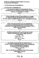
- FIG. 16 is an explanatory chart illustrating the principle of measurement of NOx concentration in the case where NO does not dissociate in the first internal space.
- FIG. 17 is an explanatory chart illustrating the principle of measurement of NOx concentration in the case where NO partially dissociates in the first internal space.
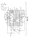
- FIG. 18 is an explanatory view showing an NOx concentration sensor used in an embodiment of the present invention.
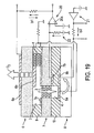
- FIG. 19 is an explanatory view showing a controller for the NOx concentration sensor used in an embodiment of the present invention.
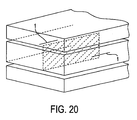
- FIG. 20 is a view showing where the sectional plane of FIG. 18 is located within the NOx concentration sensor.
- FIG. 21 is an explanatory view showing the relationship between the location of an oxygen concentration detection electrode and the distribution of oxygen concentration within the first internal space of a two-serial-space NOx sensor sample.
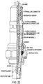
- FIG. 22 is a view showing a fitting assembly including the NOx concentration sensor of the present invention.
- FIG. 23 is a graph showing measurement results of Experiment 1, showing the offset current for Ip2 as a function of the target voltage value Vs.
- FIG. 24 is a graph showing measurement results of Experiment 1, showing the NO dissociation percentage in the first internal space as a function of Vs which corresponds to an oxygen partial pressure of the first internal space gas entering the second internal space.
- FIG. 25 is a graph showing measurement results of Experiment 2a, showing Gain of the two-serial NO sensor as a function of a oxygen concentration of the measurement gas of interest in a measurement space.
- FIG. 26 is a graph showing measurement results of Experiment 3a, used in determination of the NO dissociation percentage in the first internal space.
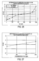
- FIG. 27 is a graph showing measurement results of Experiment 3b, used in determination of the NO dissociation percentage in the first internal space.
- FIG. 28 is a graph showing measurement results of Experiment 3c, showing NO dissociation percentage in the first internal space as a function of oxygen concentration of the measurement gas of interest entering the first internal space.
- FIG. 29 is a graph showing measurement results of Experiment 4, showing that an oxygen concentration of the measurement gas is represented as a linear function of the first pump cell current Ipl only when the measurement gas of interest does not contain NOx but only oxygen.
- FIG. 30 is an explanatory view illustrating the relationship between the inner electrode material of the first pump cell and the NO dissociation percentage in the first internal space.
- NOx concentration (gain for NOx concentration) x (variation in output from NOx concentration sensor) .
- the NOx concentration gain is the variation in NOx concentration corresponding to a constant variation in sensor output (ppm/ ⁇ A), namely, the reciprocal of sensor sensitivity.
- an electrode 6b of a first pumping cell 6 is formed along the direction of measurement gas flow.
- the first pumping cell 6 undergoes feedback control based on an output from an oxygen concentration detection electrode 7a.
- oxygen concentration detection electrode 7a detects an average oxygen concentration in a local space which faces the electrode 7a. That is, the oxygen concentration detection electrode 7a detects and outputs a local oxygen concentration in the vicinity of the center of the electrode 7a.
- the first pumping cell 6 substantially controls the oxygen concentration in the gas diffusing into a second passage such that the local oxygen concentration detected in the vicinity of the center of the oxygen concentration detection electrode 7a assumes a target oxygen concentration.
- the oxygen concentration of the local space in the vicinity of the center of the oxygen concentration detection electrode 7a agrees with the target oxygen concentration, whereas the oxygen concentration of the space located downstream of the central portion of the electrode 7a is lower than the target oxygen concentration.
- NO is more likely to dissociate, as seen from the formula "2NO ⁇ N 2 + O 2 ".
- the concentration of oxygen in the gas diffusing into the second passage is controlled so as to become constant regardless of the concentration of oxygen in the measurement gas. Accordingly, the oxygen concentration gradient in the first passage 2 becomes steeper in the case of a high oxygen content in the measurement gas than that in the case of a measurement gas having a low oxygen content. As a result, a local space having a low oxygen concentration emerges within the first passage 2. Thus, the NO dissociation percentage in the first passage 2 varies according to the concentration of oxygen in the measurement gas.
- FIG. 16 shows a process of obtaining a gain for NOx concentration in the manner of a geometrical series in the case of FIG. 15.
- a measurement gas which contains oxygen in a proportion of a and NO in a proportion of b is introduced into the NOx concentration sensor.
- Oxygen is pumped out from the first passage such that the concentration of oxygen in gas diffusing into the second passage approaches 0%.
- the measurement gas diffuses into the first passage at the same rate as that of the pumped-out oxygen.
- the gas diffusing into the second passage contains NO in a proportion of "a + ab" (steps 101 and 102).
- the step of pumping out oxygen is repeated until the concentration of oxygen in the gas diffusing into the second passage reaches a target value (step 103).
- NO gain gain 0 / ⁇ 1 - (NO dissociation percentage [%] in first passage)/100 ⁇ x ⁇ 1 - O 2 [%]/100) ⁇ is deduced (step 205).
- NO gain also varies with the NO dissociation percentage in the first passage.
- NO gain [dissociation] NO gain [no dissociation]/ ⁇ 1 - (NO dissociation percentage [%] in the first passage)/100 ⁇ .
- FIG. 20 shows where the plane of FIGS. 18 and 19 is located within a sensor element.
- the NOx concentration sensor of FIGS. 18 and 19 has a first pumping cell 6, an oxygen-concentration-measuring cell 7 and a second pumping cell 8 arranged in layers.
- a first passage 2 is provided so as to face the first pumping cell 6 and the oxygen-concentration-measuring cell 7.
- a second passage 4 is provided so as to face the second pumping cell 8.
- a first porous diffusion hole (resistance element) 1 is provided at an inlet to the first passage 2.
- a second porous diffusion hole (resistance element) 3 is provided at an inlet to the second passage 4.
- the first and second pumping cells 6 and 8, respectively, are each composed of an oxygen-ion conductive solid electrolyte layer and a pair of electrodes formed on the solid electrolyte layer.
- the oxygen-concentration-measuring cell 7 is an oxygen concentration cell for generating an electromotive force Vsm by means of a concentration cell effect (hereinafter simply referred to as electromotive Vsm) depending on the concentration of oxygen (partial pressure of oxygen) in the gas diffusing into the second passage 4.
- External circuits serving as control means 20 and 21 are connected to the NOx concentration sensor in order to control the first and second pumping cells 6 and 8, respectively. Electrodes 6b and 7a are electrically connected, and their point of connection is grounded via a resistance. The electrode 7b is electrically connected to the inverted input terminal (-) of a differential amplifier 20a. A reference voltage Vs is input to the uninverted input terminal (+) of the differential amplifier 20a. In order to control the concentration of oxygen in the gas diffusing into the second passage 4 to a target value corresponding to the reference voltage Vs, the output the differential amplifier 20a reversibly controls a first pumping current Ip1.
- the first pumping current Ip1 flows between the electrodes 6a and 6b such that the electromotive force Vsm generated between the electrodes 7a and 7b assumes the reference voltage Vs.
- Vsm electromotive force
- Vsm electromotive force
- Vsm electromotive force
- Vsm electromotive force
- Vsm electromotive force
- Vsm reference voltage
- Reference oxygen generation means 22 supplies a small current between the electrodes 7a and 7b so as to pump out oxygen toward the electrode 7b side, thereby forming a reference oxygen space around the electrode 7b.
- one or more unillustrated heaters are provided on or attached to a single side or opposite sides of a sensor element.
- the reference voltage Vs is set, which is a target value of control for the electromotive force Vsm generated between the electrodes 7a and 7b of the oxygen-concentration-measuring cell 7.
- Vs is set such that a portion of NO and O 2 in the first passage 2 dissociates so as to decrease the concentration of oxygen in the gas diffusing into the second passage 4 to as low a level as possible.
- an offset Ip2offset of the second pumping current Ip2 can be decreased as much as possible.
- Ip2offset which is described below, is a value corresponding to the concentration of oxygen contained in the gas diffusing into the second passage 4, and hereinafter may be referred to as Ip2 0 .
- the first pumping cell 6 is subjected to feedback control such that the electromotive force Vsm becomes equal to the reference voltage Vs.
- the voltage Vp2 is applied between the electrodes 8a and 8b of the second pumping cell 8 such that all of the NO diffusing into the second passage 4 dissociates.
- the first pumping current and the NO dissociation percentage are measured.
- the thus-measured relationship is stored in the form of a map or a relational expression in, for example, a memory provided in the NOx concentration sensor.
- the first pumping current is periodically measured, and an NO dissociation percentage is calculated which corresponds to an oxygen concentration at the measured first pumping current.
- the preferred embodiment of the method for measuring NOx concentration of the present invention takes into account both the dissociation of NO and an increase in NOx concentration caused by pumping out oxygen from the first passage. This preferred embodiment will next be described in detail.
- a measurement gas including NO and oxygen diffuses into the first passage 2.
- Oxygen concentration is sufficiently decreased by action of the first pumping cell, and a gas which contains residual NO diffuses into the second passage 4.
- the concentration of oxygen in the gas diffusing into the second passage must be considerably decreased.
- oxygen is sufficiently pumped out from the first passage such that a portion of NO in the first passage dissociates.
- the calculation of NOx concentration based on the first and second pumping currents Ip1 and Ip2, respectively, will next be described.
- the method for calculating NOx concentration will be schematically described using a number-of-molecules model.
- the number of O 2 molecules in the gas diffusing into the second passage is taken as 1
- the number of NO molecules in the gas diffusing into the second passage is calculated as 10 x 9,999/9,000 at steady state.
- the number of O 2 molecules in the gas diffusing into the second passage is taken as 1
- the number of NO molecules in the gas diffusing into the second passage is obtained as 9 x 9,999/9,000. This indicates that NO gain also varies as a result of the dissociation of NO in the first passage.
- the number of NO molecules can be obtained based on the concentration of oxygen (degree of enrichment of NO) in the measurement gas and the NO dissociation percentage in the first passage.
- Expressions for obtaining the concentration of NOx in the measurement gas based on Ip1 and Ip2 are shown below.
- Number of NO molecules [2st] ⁇ (number of NO molecules [m]) - (number of NO molecules [d]) ⁇ x total number of molecules - number of oxygen molecules 2st total number of molecules - number of oxygen molecules m
- the NOx concentration can be calculated based on the NO dissociation percentage in the first passage, the concentration of oxygen in the measurement gas, and the first and second pumping currents. Expressions for obtaining NOx concentration are shown below.
- NO dissociation percentage [%] ⁇ 0 + K2 x O 2 [%] + K3 x O 2 [%] 2
- NO dissociation percentage (NO which has dissociated in first passage)/(NO contained in measurement gas) x 100
- K0 is " ⁇ Ip2/ ⁇ NO concentration" obtained when the concentration of oxygen in the measurement gas is 0 ppm.
- K1 is determined by solving an approximate expression representing the relationship between oxygen concentration and " ⁇ Ip2/ ⁇ NO concentration".
- K2 and K3 are experimentally obtained from the relationship between the concentration of oxygen in the measurement gas and the NO dissociation percentage in the first passage.
- the NO dissociation percentage Ib/IB
- K4 is a gain for oxygen concentration. Ip1 is measured for a measurement gas having an NO concentration of 0 ppm and an oxygen concentration of 0% and for a measurement gas having an NO concentration of 0 ppm and a predetermined oxygen concentration. K4 is experimentally obtained from the relationship between the change in oxygen concentration with the change in Ip1.
- K5 can be obtained based on IB described above, and the NOx concentration when Ip1 has reached IB.
- concentration of NOx in the measurement gas is very small as compared to the concentration of oxygen in the measurement gas, "K5 x (NO concentration) x ( ⁇ 0 + K2 x (oxygen concentration) + K3 x (oxygen concentration) 2 )" in equation (5) may be substantially taken as 0. In this case, the concentration of oxygen in the measurement gas can be directly obtained from a measured Ip1.
- the Vs electrode 7a is preferably disposed in the vicinity of the inlet to the second porous diffusion element 3 so as to be disposed away from the first diffusion hole 1.
- the oxygen concentration of a space just above the oxygen concentration detection electrode 7a positioned at a gas inlet ( second diffusion hole 3 ) to the second passage 4 is preferably constant.
- the inner electrode 6b ( of the first pumping cell 6 ) located inside on the first passage 2 is made shorter than the length of the first passage 2 (see FIG. 21), in a gas flow direction.
- the electrode 6b is disposed at the upstream side of the first passage 2 (on the side of a measurement-gas inlet to the first passage 2 ( namely the first diffusion hole 1).
- the Vs electrode 7a is disposed at the downstream side of the first passage 2 ( on the side of the inlet to the second passage 4, namely, on the side of the second diffusion hole 3).
- the Vs electrode 7a is disposed so as to surround an opening of the second diffusion hole 3.
- the opening and the Vs electrode 7a are preferably concentric with each other.
- the Vs electrode 7a may be partially or entirely formed so as to face the second diffusion hole 3 or may be partially or entirely formed inside the second diffusion hole 3.
- the Vs electrode 7a may be formed on the opening of the second diffusion hole 3 using a porous electrode.
- a pair of the electrodes 8a and 8b of the second pumping cell 8 are formed on the same surface of a solid electrolyte layer. Only the electrode 8a is exposed to the second passage 4. Because the electrode 8b is covered, the effective voltage applied between the electrodes 8a and 8b is stabilized.
- the electrodes 8a and 8b may be formed so as to sandwich the solid electrolyte layer therebetween.
- the NO dissociation percentage in the first passage is preferably not greater than 50%, more preferably not greater than 20%, particularly preferably not greater than 15%.
- the NO dissociation percentage is preferably not less than 0.5%, more preferably not less than 1%, particularly preferably not less than 3%.
- the NO dissociation percentage can be adjusted by appropriately setting the temperature of the detection element.
- Vs corresponding to a target oxygen concentration is set such that the concentration of oxygen in the gas diffusing into the second passage becomes sufficiently low.
- An electrode of the first pumping cell located on the first passage side preferably has a catalytic activity for sufficient dissociation of oxygen and sufficient combustion of interfering gases (for example, combustible gases such as HC and CO) and a relatively suppressed catalytic activity for the dissociation of NO (in order to diffuse a sufficient quantity of NO into the second passage).
- the electrode is made of, for example, a Pt-Au alloy.
- the electrode material may contain, in place of or together with Au, a component (for example, Cu) for suppressing the catalytic activity of Pt for the dissociation of NO.
- An NOx concentration calculator calculates NOx concentration by means of a microcomputer in which the relationship between oxygen concentration and gain K as well as coefficients such as K0 are stored, into which Ip1 and Ip2 are input, and in which a calculation equation for oxygen concentration and a calculation equation for NOx concentration are programmed. Also, the concentration of oxygen in the measurement gas may be measured by means of a separate oxygen sensor. Based on the thus-measured oxygen concentration and an output from the NOx concentration sensor, NOx concentration may be determined. For example, in an automobile exhaust system, based on an output from an oxygen sensor used for detecting an air-fuel ratio, a gain for NOx concentration can be selected according to oxygen concentration. An NOx concentration sensor based on the present invention can be favorably used in an atmosphere which involves a great variation in oxygen concentration, such as an exhaust system of an internal combustion engine (particularly, an automobile lean-burn engine).
- a reference oxygen source may be so formed by directly or indirectly introducing the surrounding air having about oxygen concentration of 0.2 atm to the side of the oxygen concentration reference electrode 7b which is porous.
- oxygen may be pumped out to the side of the oxygen concentration reference electrode 7b by applying a constant small current between the electrodes 7a and 7b of the oxygen-concentration-measuring cell 7, thereby forming a reference oxygen space around or in the electrode 7b.
- the electrode 7b can be used as an oxygen self-generation-type reference electrode.
- This self-generation-type reference electrode may have an advantage in that the reference oxygen concentration is less susceptible to variations in the oxygen concentration of the surrounding air, providing a constant oxygen partial pressure reference of e.g. 2 atm.
- FIG. 22 shows the attachment of an element (hereinafter referred to as a gas sensor element) of the NOx concentration sensor shown in FIGS. 18 and 19 into a fitting assembly.
- the gas sensor element is fixed within the fitting assembly such that its measurement gas inlet (first diffusion hole) is located within a protector (protective tube) having holes formed therein.
- a heater is attached onto the gas sensor element along the longitudinal direction of the element.
- Upper portions of the gas sensor element and the heater in FIG. 22 are covered with two kinds of sealing materials.
- a lower sealing material 1) is porous to permit gas to pass therethrough.
- An upper sealing material 2) is airtight.
- a holder is disposed around the sealing materials.
- a stainless steel seal ring is fitted between the holder and a metallic shell, while sealing filler powder made of talc is filled into a space defined by the holder, the metallic shell and the seal ring.
- the lower end of the layer of the sealing filler powder abuts a flange portion of the holder.
- a tightening force acts in the radial direction of the metallic shell as well as in the axial direction of the metallic shell, thereby fixing the holder with respect to the metallic shell and holding the gas sensor element in a stable manner.
- a first outer cylinder 1) and a second outer cylinder 2) are coaxially engaged with each other.
- the first outer cylinder 1) extends into the metallic shell and is engaged with the metallic shell. Waterproof rubber is fitted into an upper portion of the second outer cylinder 2 in FIG. 22. Electrodes formed on the gas sensor element (see FIG. 18) are electrically connected to first electrode leads having a gas diffusion resistance. The first electrode leads are electrically connected to second electrode leads. The second electrode leads are electrically connected to covered lead wires via an external lead connection portion.
- the destination for oxygen pumped into a reference oxygen space formed around the reference oxygen concentration electrode is not particularly limited. For example, the oxygen may be returned to the atmosphere via the electrode leads, the measurement gas atmosphere, or a passage.
- the number of leads required for controlling and outputting a signal from the NOx concentration sensor, including a heater lead, may be seven.
- a common lead which is electrically connected to the electrodes 6b, 7a and 8a (see FIGS. 18 and 19)
- the number of leads can be reduced to six.
- the number of leads can be reduced to five.
- ZrO 2 powder (which contains a stabilizer and is hereinafter referred to simply as ZrO 2 powder) preliminarily fired in an atmospheric furnace, a dispersant, an organic solvent and balls are mixed and dispersed using a trommel. To the resulting mixture, an organic binder dissolved in an organic solvent is added, followed by mixing, to thereby obtain a slurry. The thus-obtained slurry is sheeted according to a known doctor blading method, yielding a ZrO 2 green sheet.
- Platinum powder, ZrO 2 powder and an appropriate amount of organic solvent are mixed and dispersed using a ball mill (or a pot mill).
- a ball mill or a pot mill.
- an organic binder dissolved in an organic solvent is added, and a viscosity conditioner is further added, followed by mixing, thereby yield a paste.
- Platinum powder, ZrO 2 powder and an appropriate amount of organic solvent are mixed and dispersed using a ball mill (or a pot mill).
- a ball mill or a pot mill.
- an organic binder dissolved in an organic solvent is added, and a viscosity conditioner is further added, followed by mixing, to thereby yield a paste.
- Alumina powder and an appropriate amount of organic solvent are mixed and dissolved using a ball mill (or a pot mill).
- a viscosity conditioner is added, followed by mixing, to thereby yield a paste.
- Pt-containing porous material for lead wire
- Alumina powder, platinum powder, an organic binder and an organic solvent are mixed using a ball mill (or a pot mill).
- a viscosity conditioner is added, followed by mixing, to thereby yield a paste.
- Alumina powder, an organic binder and an organic solvent are mixed and dispersed using a ball mill (or a pot mill).
- a viscosity conditioner is added, followed by mixing, to thereby yield paste.
- Carbon powder, an organic binder and an organic solvent are mixed and dispersed using a ball mill (or a pot mill).
- a viscosity conditioner is added, followed by mixing, to thereby yield a paste.
- a carbon coat layer can be formed by printing to prevent, for example, contact between the inner electrode of the first pumping cell and the oxygen concentration detection electrode.
- the carbon coat layer is also used for forming spaces serving as the first and second passages. Because carbon is burned during firing, the carbon coat layer is not present in a fired body.
- Preferred Pellet compact for second diffusion hole Preferred Pellet compact for second diffusion hole
- Alumina powder, an organic binder and an organic solvent are mixed and pelletized using a ball mill (or a pot mill).
- the resulting mixture is press-worked into a columnar pellet compact (in a green state).
- ZrO 2 green sheets of the second and third layers are united under pressure. Then, the second diffusion hole is punched in the laminated ZrO 2 green sheets. Subsequently, the above-mentioned pellet compact in the green state is embedded into the hole. Then, another zrO 2 green sheet is placed on the laminated ZrO 2 green sheets, followed by uniting under pressure.
- the pressure-united body is heated for removing binder therefrom and is then fired.
- the dimensions of an element of the NOx concentration sensor used in the Examples, which will be described later, are described below.
- the element had a length (a dimension in the longitudinal direction) of 50 mm, a width (a dimension in the lateral direction) of 4 mm, and a thickness (a dimension in the direction of lamination) of 1.3 mm.
- the first pumping cell had a thickness of 0.35 mm (resistance: 40 to 60 ⁇ at a pumping cell temperature of about 800°C).
- the second pumping cell had a thickness of 0.35 mm (resistance: 40 to 60 ⁇ at a pumping cell temperature of about 800°C).
- the electrodes 6a and 6b of the first pumping cell 6 had a longitudinal length of 7 mm and 4 mm, respectively, and a width of 2 mm.
- the electrodes 8a and 8b of the second pumping cell 8 had a longitudinal length of 7 mm and a width of 2 mm.
- the electrodes 7a and 7b of the oxygen-concentration-measuring cell 7 had a longitudinal length of 2 mm and a width of 2 mm. All of the electrodes had a thickness of 10 to 20 ⁇ m.
- the first and second passages had a height of about several tens of ⁇ m (about 50 ⁇ m).
- FIG. 1 schematically shows a longitudinal sectional view of the sensor.
- numeral 1 denotes a first diffusion passage (first diffusion resistance element); numeral 2 denotes a first space; numeral 3 denotes a second diffusion passage (second diffusion resistance element); numeral 4 denotes a second space; numerals 5-1, 5-3, and 5-5 denote three oxygen-ion conductive solid electrolyte layers in lamination, each of which is made of zirconia ceramic sheet; numeral 6 denotes a first pumping cell (an oxygen ion pumping cell is referred to as a pumping cell); numerals 6-a and 6-b denote porous electrodes of the first pumping cell; numeral 7 denotes an oxygen-concentration measuring cell; numerals 7-a and 7-b denote porous electrodes of the oxygen-concentration-measuring cells 7; numeral 8 denotes a second pumping cell; numerals 8-a and 8-b denote porous electrodes of the second pumping cell; numeral 9 denotes a reference oxygen space communicating with outside air for oxygen reference
- Insulating layers 5-2,5-4 made of alumina ceramic are interposed between the solid electrolyte layers 5-1,5-3,5-5.
- the first diffusion passage 1 is provided so as to open onto the exterior of the sensor at a longitudinal side of the sensor.
- FIG. 1 shows the first diffusion passage 1 for convenience of indication of its location.
- the diffusion passage is a diffusion resistance element having a diffusion resistance, which limits gas diffusion from the measurement gas space.
- the insulating layers 5-2, 5-4 may possibly be replaced with solid electrolyte layers.
- the porous electrode 7-a is provided on the oxygen-concentration-measuring cell 7 so as to be exposed to the first space 2 and positioned annularly around the opening of the second diffusion passage 3 (namely, a gas inlet of the second space 4).
- a constant small current is applied between the electrodes 7-a and 7-b of the oxygen-concentration-measuring cell 7 so as to pump out oxygen to the side of the electrode 7-b, thereby forming a reference oxygen space around the electrode 7-b.
- the electrode 7-b can be used as a self-generation-type reference electrode.
- the formation of such a self-generation-type reference electrode has an advantage that the reference oxygen concentration is less susceptible to changes in the oxygen concentration of the surrounding atmosphere, as previously maintained.
- the second diffusion passage 3 is located away from the first diffusion passage 1. This arrangement also enables accurate control of oxygen concentration in the vicinity of the gas inlet of the second space 4, in combination with the annularly positioned electrode 7-a. Accordingly, the oxygen concentration dependence of an offset component of the second pumping current and the oxygen concentration dependence of the NO dissociation percentage can be decreased.
- the electrode 6-b of the first pumping cell 6 exposed to the first space 2 is shorter then the first space 2 in the longitudinal direction of the first space 2 and is located so as not to hang over the second diffusion passage 3. This arrangement minimizes the effect of operation of the first pumping cell 6 on the oxygen concentration in the vicinity of the gas inlet of the second space 4 to thereby stabilize the oxygen concentration.
- a pair of the electrodes 8-a and 8-b of the second pumping cell 8 are formed on the same surface of the solid electrolyte layer 5-5.
- the electrode 8-a is exposed to the second passage 4, whereas the electrode 8-b is interposed between the layers 5-5 and 5-4.
- This arrangement has an advantage that an effective voltage applied between the electrodes 8-a and 8-b is stabilized.
- Material for the above-mentioned electrodes may be made from at lease one of metals such as platinum, palladium, rhodium, gold, silver and copper and mixing with the same ceramic components as those of the solid electrolyte layer.
- a lead of each electrode extends between the solid electrolyte layers to the right of FIG. 1.
- a terminal may be provided at the other end portion of the lead for electrical connection with a measuring circuit.
- the concentration of oxygen in the measurement gas introduced into the second space 4 from the first space 2 is monitored by measuring electromotive force voltage Vms outputted from the oxygen-concentration-measuring cell 7.
- nitrogen oxide (NO) and oxygen (O 2 ) in the first space 2 dissociate as represented by the following formulae (A2) and (A3). 2NO ⁇ N 2 + O 2 O 2 + 4e - ⁇ 2O 2-
- operation of the first pumping cell 6 is controlled so as to control oxygen concentration in the vicinity of the gas inlet of the second space 4.
- This causes NO and O 2 to dissociate to an extent such that a portion of the NO dissociates in the first space 2, namely, the percentage ⁇ of dissociation of NO contained in the measurement gas assumes a value of not less than 0.5% (for example, within a range of 2% to 20%) in the first space 2.
- the current (first pumping current) Ip1 flowing through the first pumping cell 6 is measured.
- the resulting gas after the above dissociation of NO at a predetermined percentage ⁇ of dissociation is introduced into the second space 4 through the second diffusion passage 3.
- the second pumping cell 8 residual O 2 and NO in the second space 4 are dissociated.
- Oxygen ions generated by the dissociation of O 2 and NO are pumped out by means of the second pumping cell 8.
- the current (second pumping current) Ip2 flowing through the second pumping cell 8 is measured.
- the above pumped-out oxygen ions are generated as a result of the dissociation of O 2 and NO in the gas introduced into the second space 4 from the first space 2. Accordingly, the quantity of oxygen introduced into the second space 4 from the first space 2 appears in terms of an offset component (the second pumping current as measured when the quantity of NO is zero) of the second pumping current. The rest of the second pumping current corresponds to the quantity of NO which has not dissociated in the first space 2 and which has been introduced into the second space 4.
- NO concentration is calculated by the method which will be described below in detail.
- Equation (A1) for calculating the concentration of NO in the measurement gas will next be described.
- NOx concentration (Ip2 - Ip2offset) x A/(1 - ⁇ /100)
- NOx concentration concentration of NOx in the measurement gas.
- the first pumping cell 6 is controlled such that the output voltage Vsm of the oxygen-concentration-measuring cell 7 assumes a target voltage Vs (for example, 450 mV).
- Vs for example, 450 mV
- the first pumping current is measured. That is, voltage is applied between the electrodes of the first pumping cell 6 so as to attain an oxygen concentration at which NO dissociates at a predetermined percentage ⁇ in the first space 2.
- the first pumping current corresponds to the percentage ⁇ of NO dissociating in the first space.
- the second pumping current corresponds to the quantity of oxygen ions generated as a result of the dissociation of NO an O 2 in the second space 4. That is, the second pumping current includes not only a current corresponding to NO concentration but also an offset current corresponding to oxygen concentration. Accordingly, a current corresponding to the NO concentration of the second space 4 is represented by the difference between the second pumping current Ip2 and the offset current Ip2offset (Ip2 - Ip2offset).
- the concentration of NO in the measurement gas is taken as 1
- the NO concentration of the gas introduced into the second space 4 is represented by (1 - ⁇ /100). Accordingly, a current corresponding to a total NO concentration is obtained by dividing the above-mentioned current differential (Ip2 - Ip2offset) associated with the second pumping cell 8 by the NO concentration (1 - ⁇ /100) of the gas introduced into the second space 4. Thus, the current is represented by ⁇ (Ip2 - Ip2offset)/(1 - ⁇ /100) ⁇ .
- the total NO concentration can be obtained by multiplying the above-obtained current by a predetermined conversion coefficient (a coefficient for converting current to NO concentration).
- the concentration of NO in the measurement gas can be obtained using the above Expression (A1).
- FIG. 2 shows an example map M1 representing such a relationship.
- FIG. 3 shows an example map M2 representing such a relationship.
- the above relationship is obtained using a gas which does not contain NO.
- the measured second pumping current Ip2 becomes the offset current Ip2offset.
- FIG. 4 shows an example map M3 representing such a relationship.
- This gain expressed as A/(1 - ⁇ /100) is a multiplier used in calculation of NO concentration and is a function of the experimentally obtained target voltage Vs and oxygen concentration. Specifically, the gain is determined with the conversion coefficient A (:coefficient for conversion of current to NO concentration) given at an NO dissociation percentage of 0% while the percentage ⁇ of dissociation of NO is taken into account. The gain indicates variation in NO concentration corresponding to variation in second pump current Ip2.
- the gain is the reciprocal of sensitivity, namely, the reciprocal of a value obtained by dividing second pump current (corresponding to NO dissociation in the second internal space) by NO concentration in the measurement gas.
- the value has the unit of for example, ⁇ A/ppm.
- FIG. 6 By measuring a measurement gas having a known NO concentration and oxygen concentration, the relationship shown in FIG. 6 is obtained among the second pumping current Ip2, oxygen concentration and NO concentration.
- an NO concentration e.g., 200 ppm
- a current differential (Ip2 - Ip2offset) corresponding to a certain oxygen concentration represents a true current value corresponding to the NO concentration.
- sensitivity is obtained. The reciprocal of the thus-obtained sensitivity is the gain.
- the map M3 of FIG. 4 showing the relationship among gain, target voltage Vs, and oxygen concentration is prepared in advance.
- the NOx concentration sensor is placed in a measurement space filled with a measurement gas of interest having an unknown NO concentration.
- the measurement gas is introduced into the first space 2 via the first diffusion passage 1.
- the operation of the first pumping cell 6 partially dissociates NO and O 2 contained in the measurement gas introduced into the first space 2 so as to attain a predetermined NO dissociation percentage ⁇ (at least 0.5%) forming a new gas at the inlet of the second space 4.
- a first pumping current Ip1 flows through corresponding to the extent of the dissociation. At this time, the first pumping current Ip1 is measured.
- the new gas leaves the first space 2 to enter the second space 4 via the second diffusion passage 3.
- the new gas contains residual O 2 and NO which have not been dissociated in the first space 2.
- the concentration of oxygen in the measurement gas corresponding to the target voltage Vs is obtained.
- the offset current Ip2offset corresponding to the target voltage Vs is obtained.
- the gain represented as A/(1 - ⁇ /100) corresponding to the target voltage Vs is obtained.
- FIG. 7 shows the relationship between oxygen concentration and gain while the target voltage Vs set for the oxygen-concentration-measuring cell 7 is specified as a parameter.
- FIG. 7 is a detailed graph of FIG. 4 and shows the variation in gain for different values of the target voltage Vs.
- the solid line represents a mean gain
- the dashed line represents a minimum gain
- the dotted line represents a maximum gain.
- the target voltage Vs set for the oxygen-concentration-measuring cell 7 when the target voltage Vs set for the oxygen-concentration-measuring cell 7 is low, the gain shows a large variation and is thus unstable. Variation in the gain increases with oxygen concentration of the measurement gas. Accordingly, the target voltage Vs is preferably set not lower than a certain value (e.g. 350 mV).
- This variation in gain is considered to arise as follows.
- the target voltage Vs is preferably set not lower than the certain value (350 mV), in order to minimize the gain variation.
- Setting the target voltage Vs not lower than a certain value means setting the percentage ⁇ of dissociation of NO in the first space 2 to not less than a certain value (0.5%). This indicates the importance of setting the percentage ⁇ of dissociation of NO in the first space 2 to a predetermined value of not less than a certain value.
- the NO dissociation percentage ⁇ in the first internal space is preferably fixed by controlling the temperature drift of the first space 2 inside the sensor with a heater 10, because as indicated in Fig. 5 the temperature affects the dissociation percentage.
- the percentage ⁇ of dissociation of NO and the target voltage Vs set across the electrodes 7a, 7b of the oxygen-concentration-measuring cell 7 have the relationship shown in FIG. 8.
- setting the target voltage Vs not lower than a certain value means setting the percentage ⁇ of dissociation of NO to not less than a certain value (0.5%).
- the NO dissociation percentage is preferably, for example, not less than 0.5%. However, although the gain variation is decreased, too high a NO dissociation percentage raises a problem in obtaining the gain itself. Therefore, the NO dissociation percentage is most preferably not greater than a certain value, which would be about 20 % as shown in Fig.13.
- FIGS. 9 to 12 show the results of experiments on sensor output.
- the experiments used NOx sensors having a porous electrode having different Au contents and Pt as a main component to thereby impart a percentage ⁇ of dissociation of NO of 4.4%, 23.7%, 28.1% and 56.7% to the respective sensors.
- sensor output was measured at an oxygen concentration of 0%, 1%, 6% and 15%.
- FIG. 9A, FIG. 10A, FIG. 11A and FIG. 12A show the relationship between the sensor output indicative of NO concentration and the actual NO concentration, for each of the oxygen concentrations.
- FIG. 9B, FIG. 10B, FIG. 11B and FIG. 12B show the relationship between deviation in sensor output and the actual NO concentration, for each of the oxygen concentrations.
- the NOx analyzer used in the experiments employed a known Chemical Luminescence Detection or CLD method.
- the NOx analyzer output is referred to as the actual NO concentration.
- the graph of FIG. 13 summarizes the experimental results of FIGS. 9 to 12. As seen from FIG. 13, when the NO dissociation percentage is too large, deviation in sensor output becomes large, and consequently accuracy in measuring NO concentration deteriorates.
- the case of FIG. 13 employed an NO concentration, O 2 concentration, sensor temperature and voltage (Vs) as specified therein.
- the NO dissociation percentage is preferably not greater than 50%, more preferably not greater than 30%, particularly preferably not greater than 20%.
- the air having 0.2 atm oxygen partial pressure may be introduced to the NOx concentration cell reference electrode instead of using such an oxygen self-generation-type reference electrode for a reference oxygen space.
- a pair of electrodes of the second pumping cell may be formed on opposite surfaces of the solid electrolyte layer of the cell at opposite positions.
- one or more heaters may be preferably disposed on a single side or both sides of the NOx concentration sensor so as to control the sensor temperature drift as small as possible in the predetermined temperature of 550°C to 900°C.
- the NOx concentration sensor is preferably used within a temperature range in which the NO dissociation percentage does not vary greatly, for example, a range of 700°C to 850°C, preferably a range of 770°C to 820°C.
- the temperature of the sensor used in the present invention is kept constant during NOx concentration measurement.
- an apparatus for measuring NOx concentration according to an embodiment of the invention and a method for measuring NOx concentration employing the apparatus will next be described.
- NOx concentration sensor as may be shown in FIGS. 18 and 19, the concentration of NOx contained in a measurement gas is measured while the sensor is controlled as described above.
- NO is selected as a nitrogen oxide to be measured;
- the sensor-element temperature of the NOx concentration sensor is 800°C; and the temperature of the measurement gas introduced into the sensor is 300°C.
- Vp2 applied between the two electrodes of the second pumping cell is 450 mV.
- the measurement gas has an oxygen concentration of 7%, a CO 2 concentration of 10%, and an H 2 O concentration of 10%.
- the relationship between the voltage Vs set for the oxygen-concentration-measuring cell and the offset current (Ip2 0 ) of the second pumping current Ip2 is examined. The results are shown in FIG. 23.
- Vs When Vs is set high, the concentration of oxygen in the gas diffusing into the second passage decreases.
- Vs is set low, the concentration of oxygen in the gas diffusing into the second passage increases.
- FIG. 24 shows the relationship between Vs and the NO dissociation percentage in the first passage. As seen from FIG. 24, when Vs is high, namely, when oxygen concentration is low, the NO dissociation percentage is large. The method for calculating the percentage of NO will be described below.
- Vs is preferably set to not less than 300 mV, more preferably not less than 320 mV.
- Vs in order to stabilize the NO dissociation percentage in the first passage, Vs is preferably set to not greater than 500 mV.
- Vs is more preferably set to not less than 350 mV and not greater than 450 mV.
- the most preferable Vs range is from about 400 mV to about 450 mV, because there starts to appear a substantial influence from moisture dissociation when Vs exceeds 450 mV particularly beyond 500 mV and that range renders the best NOx measurement accuracy.
- EXPERIMENT 2A MEASURED GAIN FOR NOX CONCENTRATION
- Gain K in NOx concentration is obtained from the difference between Ip2 measured at an NO concentration of 1,500 ppm and Ip2 measured at an NO concentration of 0 ppm.
- the solid line of FIG. 25 represents the relationship between the thus-obtained gain K (measured gain) and oxygen concentration. Based on the relationship thus obtained, coefficients K0 and K1 in equation (2) shown previously are obtained, thereby deducing equation (7) shown below.
- a Vs of 350 mV corresponds to an average partial pressure of oxygen of about 2 x 10 -7 as measured at the oxygen concentration detection electrode, if the detection electrode is paired with a counter electrode referencing to the atmosphere having an oxygen partial pressure of 2 x 10 -0 , according to the Nernst Equation.
- K [ppm/ ⁇ A] 176.05 - 1.3564 x O 2 [%]
- NO concentration ⁇ 176.05 - 1.3564 x O 2 [%] ⁇ x ⁇ Ip2
- EXPERIMENT 2B THEORETICAL GAIN FOR NOX CONCENTRATION
- gain K in NOx concentration as obtained while taking into account oxygen pumped out from the first passage is represented by equation (8) shown below (see step 205 in FIG. 16).
- the dotted line of FIG. 25 represents the relationship between oxygen concentration and theoretical gain K that is obtained assuming that NO does not dissociate in the first passage.
- a theoretical gain at an oxygen concentration of 0% was obtained based on gain K0 (gain as measured when NO dissociates in the first passage) as measured at a measurement gas/oxygen concentration of 0% and a percentage ⁇ of dissociation of NO of 0% at an oxygen concentration of 0%.
- a method for calculating ⁇ 0 will be described below.
- Theoretical K [ppm/ ⁇ A] K0/(1 - ⁇ 0) x (1 - O 2 [%]/100)
- the measured gain decreases to a lesser degree (namely, sensitivity increases to a lesser degree) in relation to an increase in oxygen concentration as compared with the theoretical gain. That is, the actual increase in concentration (enrichment) of NO in the first passage, which increase occurs as a result of pumping out oxygen from the first passage, is smaller than the theoretical increase. This indicates that NO can dissociate partially and stably in the first passage of the sensor.
- Equation (2) shown previously represents gain K in NOx concentration taking into account the enrichment of NO derived from pumping out oxygen from the first passage and the effect of the dissociation of NO in the first passage.
- Equation (3) shown previously represents NOx concentration, taking into account the enrichment of NO derived from pumping out oxygen from the first passage and the effect of the dissociation of NO in the first passage.
- the difference between Ip1 as measured at a predetermined NO concentration and Ip1 as measured at an NO concentration of 0 ppm is the current Ib generated by the dissociation of NO.
- EXPERIMENT 3C CALCULATION OF THE NO DISSOCIATION PERCENTAGE AT AN OXYGEN CONCENTRATION OF OTHER THAN 0%
- the NO dissociation percentage in the first passage is determined in relation to oxygen concentration in the measurement gas of interest. The results are shown in FIG. 28.
- Equation (5) Using a measurement gas having an NO concentration of 0 ppm, Ip1 was measured while the oxygen concentration is varied. The results are shown in FIG. 29. Based on these results, K4 and Ip1 0 appearing in Equation (5) shown previously are obtained. By substituting the thus-obtained K4 and Ip1 0 as well as the previously obtained NO dissociation percentage and other factors into equation (5), equation (11) shown below is obtained.
- NO 1,500 ppm
- oxygen concentration 0%
- balance nitrogen gas.
- Au and/or Cu is preferably added to Pt in an amount of 0.1% by weight to several % by weight or 0.5% by weight to 3% by weight, to thereby control or rather stabilize the NO dissociation percentage to a constant value of from 0.5% to 20% or of 2% to 15%, respectively, for maintaining oxygen concentration of the gas entering the second passage (second space) to a lowest value under Vs control.
- the concentration of NOx in a measurement gas of the present invention as well as the NOx concentration sensor of the invention, while oxygen concentration in the vicinity of the gas inlet of the second space is decreased such that a portion of NO dissociates in the first space, NOx concentration is measured based on a current signal issuing from the first pumping cell and a current signal issuing from the second pumping cell.
- NOx concentration is measured based on a current signal issuing from the first pumping cell and a current signal issuing from the second pumping cell.
- the NOx concentration sensor is controlled such that NO dissociates in the first passage, thereby decreasing the oxygen concentration dependence and temperature dependence of the NOx concentration measurement. Furthermore, the calculation of NOx concentration takes into consideration the NO dissociation percentage in the first passage, so as to provide NOx concentration with high accuracy.
Landscapes
- Chemical & Material Sciences (AREA)
- Life Sciences & Earth Sciences (AREA)
- Health & Medical Sciences (AREA)
- Physics & Mathematics (AREA)
- Chemical Kinetics & Catalysis (AREA)
- Electrochemistry (AREA)
- Molecular Biology (AREA)
- Analytical Chemistry (AREA)
- Biochemistry (AREA)
- General Health & Medical Sciences (AREA)
- General Physics & Mathematics (AREA)
- Immunology (AREA)
- Pathology (AREA)
- Measuring Oxygen Concentration In Cells (AREA)
- Investigating Or Analyzing Materials By The Use Of Fluid Adsorption Or Reactions (AREA)
Applications Claiming Priority (12)
| Application Number | Priority Date | Filing Date | Title |
|---|---|---|---|
| JP705998 | 1998-01-16 | ||
| JP705998 | 1998-01-16 | ||
| JP3889998 | 1998-02-20 | ||
| JP5612798 | 1998-02-20 | ||
| JP5612798 | 1998-02-20 | ||
| JP3889998 | 1998-02-20 | ||
| JP10929698 | 1998-04-20 | ||
| JP10929698 | 1998-04-20 | ||
| JP20056698 | 1998-07-15 | ||
| JP20056698 | 1998-07-15 | ||
| JP29310898 | 1998-09-30 | ||
| JP29310898 | 1998-09-30 |
Publications (3)
| Publication Number | Publication Date |
|---|---|
| EP0930501A2 true EP0930501A2 (fr) | 1999-07-21 |
| EP0930501A3 EP0930501A3 (fr) | 2002-04-24 |
| EP0930501B1 EP0930501B1 (fr) | 2007-07-18 |
Family
ID=27548019
Family Applications (1)
| Application Number | Title | Priority Date | Filing Date |
|---|---|---|---|
| EP99101007A Expired - Lifetime EP0930501B1 (fr) | 1998-01-16 | 1999-01-18 | Procédé pour mesurer la concentration de NOx |
Country Status (3)
| Country | Link |
|---|---|
| US (1) | US6344134B1 (fr) |
| EP (1) | EP0930501B1 (fr) |
| DE (1) | DE69936553T2 (fr) |
Cited By (4)
| Publication number | Priority date | Publication date | Assignee | Title |
|---|---|---|---|---|
| EP1739416A2 (fr) * | 2005-07-01 | 2007-01-03 | NGK Spark Plug Company Limited | Capteur de gaz multi-cellulaire avec chauffage |
| WO2008107229A1 (fr) * | 2007-03-07 | 2008-09-12 | Robert Bosch Gmbh | Détecteur de gaz pour mesurer un constituant gazeux dans un mélange gazeux |
| EP2490018A3 (fr) * | 2011-02-17 | 2014-06-25 | NGK Spark Plug Co., Ltd. | Appareil de détection de concentration de Nox et procédé de détection de concentration de nox |
| CN109416341A (zh) * | 2016-06-23 | 2019-03-01 | 日本碍子株式会社 | 气体传感器以及被测定气体中的多个目标成分的浓度测定方法 |
Families Citing this family (20)
| Publication number | Priority date | Publication date | Assignee | Title |
|---|---|---|---|---|
| JP3534612B2 (ja) * | 1998-05-18 | 2004-06-07 | 日本特殊陶業株式会社 | 平面型限界電流式センサ |
| WO2003083465A1 (fr) * | 2002-03-29 | 2003-10-09 | Ngk Spark Plug Co.,Ltd. | Dispositif de mesure de nox, dispositif d'autodiagnostic de capteur de nox, et procede d'autodiagnostic correspondant |
| JP3835439B2 (ja) * | 2003-08-20 | 2006-10-18 | トヨタ自動車株式会社 | 濃度検出装置 |
| US20080017510A1 (en) * | 2004-05-26 | 2008-01-24 | Nair Balakrishnan G | NOx Gas Sensor Method and Device |
| US7114325B2 (en) * | 2004-07-23 | 2006-10-03 | Ford Global Technologies, Llc | Control system with a sensor |
| DE102006014892B4 (de) * | 2005-03-31 | 2020-09-24 | Ngk Spark Plug Co., Ltd. | Gassensorelement, Verfahren zu seiner Herstellung, und Gassensor |
| US20060231422A1 (en) * | 2005-04-14 | 2006-10-19 | Honeywell International Inc. | Switched gas sensor |
| US7611612B2 (en) * | 2005-07-14 | 2009-11-03 | Ceramatec, Inc. | Multilayer ceramic NOx gas sensor device |
| US7820028B2 (en) * | 2005-09-02 | 2010-10-26 | Honeywell International Inc. | Oxides of nitrogen gas sensors and methods |
| WO2008103311A2 (fr) * | 2007-02-16 | 2008-08-28 | Ceramatec, Inc. | Capteur de nox à sélectivité et sensibilité améliorées |
| US20080206107A1 (en) * | 2007-02-23 | 2008-08-28 | Honeywell International Inc. | Gas sensor apparatus for automotive exhaust gas applications |
| US7805992B2 (en) * | 2007-03-27 | 2010-10-05 | Honeywell International Inc. | Gas sensor housing for use in high temperature gas environments |
| US20090020422A1 (en) * | 2007-07-18 | 2009-01-22 | Honeywell International, Inc. | Sensor Assemblies For Analyzing NO and NO2 Concentrations In An Emission Gas And Methods For Fabricating The Same |
| US7827848B2 (en) * | 2007-08-15 | 2010-11-09 | Delphi Technologies, Inc. | Oxygen sensor and method for manufacturing the oxygen sensor |
| US20100122916A1 (en) * | 2008-11-19 | 2010-05-20 | Nair Balakrishnan G | Sensor with electrodes of a same material |
| US9164080B2 (en) | 2012-06-11 | 2015-10-20 | Ohio State Innovation Foundation | System and method for sensing NO |
| WO2015129618A1 (fr) * | 2014-02-28 | 2015-09-03 | 栗田工業株式会社 | Procédé et dispositif permettant de commander le chargement de substance chimique dans une chaudière |
| DE102017200549A1 (de) * | 2017-01-16 | 2018-07-19 | Robert Bosch Gmbh | Verfahren zur Überprüfung der Funktionsfähigkeit eines Stickoxid-Sensors |
| US11002700B2 (en) | 2017-11-21 | 2021-05-11 | Honeywell International Inc. | High temperature gas sensor |
| DE112019002904T5 (de) * | 2018-06-08 | 2021-03-04 | Denso Corporation | Messvorrichtung für eine Gaskonzentration und ein Herstellungsverfahren für selbige |
Citations (6)
| Publication number | Priority date | Publication date | Assignee | Title |
|---|---|---|---|---|
| EP0678740A1 (fr) * | 1994-04-21 | 1995-10-25 | Ngk Insulators, Ltd. | Méthode et dispositif pour mesurer un composant de gaz |
| GB2288873A (en) * | 1994-04-28 | 1995-11-01 | Univ Middlesex Serv Ltd | Multi-component gas analysis apparatus |
| EP0791828A1 (fr) * | 1996-02-23 | 1997-08-27 | Ngk Insulators, Ltd. | Méthode pour mesurer l'oxyde d'azote |
| EP0810430A2 (fr) * | 1996-05-31 | 1997-12-03 | Ngk Spark Plug Co., Ltd | Capteur et méthode pour mesurer la concentration d'oxydes d'azote |
| EP0831322A2 (fr) * | 1996-09-19 | 1998-03-25 | Ngk Insulators, Ltd. | Capteur de gaz |
| EP0878709A2 (fr) * | 1997-03-21 | 1998-11-18 | NGK Spark Plug Co. Ltd. | Procédé et appareil de mesure de la concentration d'oxydes d'azote |
Family Cites Families (9)
| Publication number | Priority date | Publication date | Assignee | Title |
|---|---|---|---|---|
| US4272329A (en) | 1980-03-03 | 1981-06-09 | Ford Motor Company | Steady state mode oxygen sensor and method |
| JPH0820410B2 (ja) | 1988-02-19 | 1996-03-04 | 日産自動車株式会社 | 窒素酸化物濃度の計測装置 |
| US5034112A (en) | 1988-05-19 | 1991-07-23 | Nissan Motor Company, Ltd. | Device for measuring concentration of nitrogen oxide in combustion gas |
| US4909072A (en) | 1988-07-22 | 1990-03-20 | Ford Motor Company | Measurement and control of exhaust gas recirculation with an oxygen pumping device |
| CA1321618C (fr) | 1988-09-30 | 1993-08-24 | Eleftherios M. Logothetis | Capteur permettant de determiner la proportion de gaz oxygenes dans un melange gazeux |
| US5145566A (en) | 1988-09-30 | 1992-09-08 | Ford Motor Company | Method for determining relative amount of oxygen containing gas in a gas mixture |
| US5672811A (en) | 1994-04-21 | 1997-09-30 | Ngk Insulators, Ltd. | Method of measuring a gas component and sensing device for measuring the gas component |
| JP3436611B2 (ja) * | 1995-04-28 | 2003-08-11 | 日本特殊陶業株式会社 | 酸素センサ用ヒータの通電制御方法及び装置 |
| JP3671100B2 (ja) * | 1996-02-23 | 2005-07-13 | 日本碍子株式会社 | 酸化物センサ |
-
1999
- 1999-01-15 US US09/232,001 patent/US6344134B1/en not_active Expired - Lifetime
- 1999-01-18 EP EP99101007A patent/EP0930501B1/fr not_active Expired - Lifetime
- 1999-01-18 DE DE69936553T patent/DE69936553T2/de not_active Expired - Lifetime
Patent Citations (6)
| Publication number | Priority date | Publication date | Assignee | Title |
|---|---|---|---|---|
| EP0678740A1 (fr) * | 1994-04-21 | 1995-10-25 | Ngk Insulators, Ltd. | Méthode et dispositif pour mesurer un composant de gaz |
| GB2288873A (en) * | 1994-04-28 | 1995-11-01 | Univ Middlesex Serv Ltd | Multi-component gas analysis apparatus |
| EP0791828A1 (fr) * | 1996-02-23 | 1997-08-27 | Ngk Insulators, Ltd. | Méthode pour mesurer l'oxyde d'azote |
| EP0810430A2 (fr) * | 1996-05-31 | 1997-12-03 | Ngk Spark Plug Co., Ltd | Capteur et méthode pour mesurer la concentration d'oxydes d'azote |
| EP0831322A2 (fr) * | 1996-09-19 | 1998-03-25 | Ngk Insulators, Ltd. | Capteur de gaz |
| EP0878709A2 (fr) * | 1997-03-21 | 1998-11-18 | NGK Spark Plug Co. Ltd. | Procédé et appareil de mesure de la concentration d'oxydes d'azote |
Cited By (9)
| Publication number | Priority date | Publication date | Assignee | Title |
|---|---|---|---|---|
| EP1739416A2 (fr) * | 2005-07-01 | 2007-01-03 | NGK Spark Plug Company Limited | Capteur de gaz multi-cellulaire avec chauffage |
| EP1739416A3 (fr) * | 2005-07-01 | 2007-05-30 | NGK Spark Plug Company Limited | Capteur de gaz multi-cellulaire avec chauffage |
| US8012325B2 (en) | 2005-07-01 | 2011-09-06 | Ngk Spark Plug Co., Ltd. | Plural-cell gas sensor with heater |
| WO2008107229A1 (fr) * | 2007-03-07 | 2008-09-12 | Robert Bosch Gmbh | Détecteur de gaz pour mesurer un constituant gazeux dans un mélange gazeux |
| US8343322B2 (en) | 2007-03-07 | 2013-01-01 | Robert Bosch Gmbh | Gas sensor for measuring a gas component in a gas mixture |
| EP2490018A3 (fr) * | 2011-02-17 | 2014-06-25 | NGK Spark Plug Co., Ltd. | Appareil de détection de concentration de Nox et procédé de détection de concentration de nox |
| CN109416341A (zh) * | 2016-06-23 | 2019-03-01 | 日本碍子株式会社 | 气体传感器以及被测定气体中的多个目标成分的浓度测定方法 |
| EP3477291A4 (fr) * | 2016-06-23 | 2019-11-13 | NGK Insulators, Ltd. | Capteur de gaz et procédé de mesure des concentrations d'une pluralité de composants cibles dans un gaz devant être mesuré |
| US11249045B2 (en) | 2016-06-23 | 2022-02-15 | Ngk Insulators, Ltd. | Gas sensor, and method for measuring concentrations of plurality of target components in gas to be measured |
Also Published As
| Publication number | Publication date |
|---|---|
| EP0930501B1 (fr) | 2007-07-18 |
| EP0930501A3 (fr) | 2002-04-24 |
| DE69936553T2 (de) | 2008-03-20 |
| US6344134B1 (en) | 2002-02-05 |
| DE69936553D1 (de) | 2007-08-30 |
Similar Documents
| Publication | Publication Date | Title |
|---|---|---|
| US6344134B1 (en) | Method for measuring NOx concentration and NOx concentration sensor | |
| EP1077375B1 (fr) | Procédé et appareil de mesure de la concentration d'oxydes d'azote | |
| JP3537628B2 (ja) | 窒素酸化物の測定方法 | |
| EP3051282B1 (fr) | Capteur de gaz | |
| US20180094564A1 (en) | Gas sensor, catalyst diagnosis system, and catalyst diagnostic method | |
| US6787014B2 (en) | Gas-detecting element and gas-detecting device comprising same | |
| US8409414B2 (en) | Gas sensor and nitrogen oxide sensor | |
| US5236569A (en) | Air/fuel ratio sensor having resistor for limiting leak current from pumping cell to sensing cell | |
| EP0845670B1 (fr) | Méthode et appareil pour mesurer la concentration d'oxydes d'azote | |
| US6695964B1 (en) | Method and apparatus for measuring NOx gas concentration | |
| US6205843B1 (en) | Gas sensing element and a method for measuring a specific gas concentration | |
| EP0791828A1 (fr) | Méthode pour mesurer l'oxyde d'azote | |
| EP0816836B1 (fr) | Capteur de gaz, méthode pour contrôler le capteur de gaz et la concentration de gaz | |
| JP3372186B2 (ja) | ガスセンサの補正方法及びガス濃度測定システム | |
| EP0743431B1 (fr) | Méthode et système de détection de la détérioration d'un catalyseur de gaz d'échappement | |
| US6093294A (en) | Gas sensor and gas concentration controller | |
| JP3621827B2 (ja) | 窒素酸化物濃度の測定方法及び測定装置 | |
| JP3176890B2 (ja) | 被測定ガス中の窒素酸化物濃度の測定方法及び窒素酸化物濃度検出器 | |
| US20230296553A1 (en) | Gas sensor | |
| JP3499421B2 (ja) | NOxガス濃度測定方法及びNOxガス濃度検出器 | |
| US6623617B2 (en) | Method and apparatus for measuring concentration of a component in a gas | |
| US20050235631A1 (en) | Sensor element for a sensor for determining the oxygen concentration in the exhaust gas of internal combustion engines | |
| JP2002333429A (ja) | NOxガス濃度測定方法及びNOxガス濃度検出器 | |
| US10859526B2 (en) | Gas sensor with a pump cell |
Legal Events
| Date | Code | Title | Description |
|---|---|---|---|
| PUAI | Public reference made under article 153(3) epc to a published international application that has entered the european phase |
Free format text: ORIGINAL CODE: 0009012 |
|
| AK | Designated contracting states |
Kind code of ref document: A2 Designated state(s): AT BE CH CY DE DK ES FI FR GB GR IE IT LI LU MC NL PT SE Kind code of ref document: A2 Designated state(s): DE FR GB |
|
| AX | Request for extension of the european patent |
Free format text: AL;LT;LV;MK;RO;SI |
|
| PUAL | Search report despatched |
Free format text: ORIGINAL CODE: 0009013 |
|
| AK | Designated contracting states |
Kind code of ref document: A3 Designated state(s): AT BE CH CY DE DK ES FI FR GB GR IE IT LI LU MC NL PT SE |
|
| AX | Request for extension of the european patent |
Free format text: AL;LT;LV;MK;RO;SI |
|
| RIC1 | Information provided on ipc code assigned before grant |
Free format text: 7G 01N 27/417 A, 7G 01N 27/419 B |
|
| 17P | Request for examination filed |
Effective date: 20020808 |
|
| AKX | Designation fees paid |
Free format text: DE FR GB |
|
| 17Q | First examination report despatched |
Effective date: 20041008 |
|
| GRAP | Despatch of communication of intention to grant a patent |
Free format text: ORIGINAL CODE: EPIDOSNIGR1 |
|
| RTI1 | Title (correction) |
Free format text: METHOD FOR MEASURING NOX CONCENTRATION |
|
| GRAS | Grant fee paid |
Free format text: ORIGINAL CODE: EPIDOSNIGR3 |
|
| GRAA | (expected) grant |
Free format text: ORIGINAL CODE: 0009210 |
|
| AK | Designated contracting states |
Kind code of ref document: B1 Designated state(s): DE FR GB |
|
| REG | Reference to a national code |
Ref country code: GB Ref legal event code: FG4D |
|
| REF | Corresponds to: |
Ref document number: 69936553 Country of ref document: DE Date of ref document: 20070830 Kind code of ref document: P |
|
| ET | Fr: translation filed | ||
| PLBE | No opposition filed within time limit |
Free format text: ORIGINAL CODE: 0009261 |
|
| STAA | Information on the status of an ep patent application or granted ep patent |
Free format text: STATUS: NO OPPOSITION FILED WITHIN TIME LIMIT |
|
| 26N | No opposition filed |
Effective date: 20080421 |
|
| REG | Reference to a national code |
Ref country code: FR Ref legal event code: PLFP Year of fee payment: 18 |
|
| REG | Reference to a national code |
Ref country code: FR Ref legal event code: PLFP Year of fee payment: 19 |
|
| PGFP | Annual fee paid to national office [announced via postgrant information from national office to epo] |
Ref country code: FR Payment date: 20161215 Year of fee payment: 19 |
|
| PGFP | Annual fee paid to national office [announced via postgrant information from national office to epo] |
Ref country code: DE Payment date: 20170110 Year of fee payment: 19 |
|
| PGFP | Annual fee paid to national office [announced via postgrant information from national office to epo] |
Ref country code: GB Payment date: 20170118 Year of fee payment: 19 |
|
| REG | Reference to a national code |
Ref country code: DE Ref legal event code: R119 Ref document number: 69936553 Country of ref document: DE |
|
| GBPC | Gb: european patent ceased through non-payment of renewal fee |
Effective date: 20180118 |
|
| PG25 | Lapsed in a contracting state [announced via postgrant information from national office to epo] |
Ref country code: DE Free format text: LAPSE BECAUSE OF NON-PAYMENT OF DUE FEES Effective date: 20180801 Ref country code: FR Free format text: LAPSE BECAUSE OF NON-PAYMENT OF DUE FEES Effective date: 20180131 |
|
| REG | Reference to a national code |
Ref country code: FR Ref legal event code: ST Effective date: 20180928 |
|
| PG25 | Lapsed in a contracting state [announced via postgrant information from national office to epo] |
Ref country code: GB Free format text: LAPSE BECAUSE OF NON-PAYMENT OF DUE FEES Effective date: 20180118 |