EP0930407A1 - Arrangement for securing a scaffold-structure - Google Patents
Arrangement for securing a scaffold-structure Download PDFInfo
- Publication number
- EP0930407A1 EP0930407A1 EP98403118A EP98403118A EP0930407A1 EP 0930407 A1 EP0930407 A1 EP 0930407A1 EP 98403118 A EP98403118 A EP 98403118A EP 98403118 A EP98403118 A EP 98403118A EP 0930407 A1 EP0930407 A1 EP 0930407A1
- Authority
- EP
- European Patent Office
- Prior art keywords
- finger
- opening
- construction
- hook
- scaffolding
- Prior art date
- Legal status (The legal status is an assumption and is not a legal conclusion. Google has not performed a legal analysis and makes no representation as to the accuracy of the status listed.)
- Granted
Links
Images


Classifications
-
- E—FIXED CONSTRUCTIONS
- E04—BUILDING
- E04G—SCAFFOLDING; FORMS; SHUTTERING; BUILDING IMPLEMENTS OR AIDS, OR THEIR USE; HANDLING BUILDING MATERIALS ON THE SITE; REPAIRING, BREAKING-UP OR OTHER WORK ON EXISTING BUILDINGS
- E04G3/00—Scaffolds essentially supported by building constructions, e.g. adjustable in height
- E04G3/24—Scaffolds essentially supported by building constructions, e.g. adjustable in height specially adapted for particular parts of buildings or for buildings of particular shape, e.g. chimney stacks or pylons
- E04G3/26—Scaffolds essentially supported by building constructions, e.g. adjustable in height specially adapted for particular parts of buildings or for buildings of particular shape, e.g. chimney stacks or pylons specially adapted for working on roofs
-
- E—FIXED CONSTRUCTIONS
- E04—BUILDING
- E04G—SCAFFOLDING; FORMS; SHUTTERING; BUILDING IMPLEMENTS OR AIDS, OR THEIR USE; HANDLING BUILDING MATERIALS ON THE SITE; REPAIRING, BREAKING-UP OR OTHER WORK ON EXISTING BUILDINGS
- E04G21/00—Preparing, conveying, or working-up building materials or building elements in situ; Other devices or measures for constructional work
- E04G21/32—Safety or protective measures for persons during the construction of buildings
- E04G21/3204—Safety or protective measures for persons during the construction of buildings against falling down
- E04G21/3214—Means for working on roofs
-
- E—FIXED CONSTRUCTIONS
- E04—BUILDING
- E04G—SCAFFOLDING; FORMS; SHUTTERING; BUILDING IMPLEMENTS OR AIDS, OR THEIR USE; HANDLING BUILDING MATERIALS ON THE SITE; REPAIRING, BREAKING-UP OR OTHER WORK ON EXISTING BUILDINGS
- E04G3/00—Scaffolds essentially supported by building constructions, e.g. adjustable in height
- E04G3/24—Scaffolds essentially supported by building constructions, e.g. adjustable in height specially adapted for particular parts of buildings or for buildings of particular shape, e.g. chimney stacks or pylons
- E04G3/26—Scaffolds essentially supported by building constructions, e.g. adjustable in height specially adapted for particular parts of buildings or for buildings of particular shape, e.g. chimney stacks or pylons specially adapted for working on roofs
- E04G3/265—Scaffolds essentially supported by building constructions, e.g. adjustable in height specially adapted for particular parts of buildings or for buildings of particular shape, e.g. chimney stacks or pylons specially adapted for working on roofs with means to adapt it to a variable pitch of the roof
-
- E—FIXED CONSTRUCTIONS
- E04—BUILDING
- E04G—SCAFFOLDING; FORMS; SHUTTERING; BUILDING IMPLEMENTS OR AIDS, OR THEIR USE; HANDLING BUILDING MATERIALS ON THE SITE; REPAIRING, BREAKING-UP OR OTHER WORK ON EXISTING BUILDINGS
- E04G5/00—Component parts or accessories for scaffolds
- E04G5/04—Means for fastening, supporting, or bracing scaffolds on or against building constructions
- E04G5/041—Means for fastening, supporting, or bracing scaffolds on or against building constructions for fastening scaffolds on roof frameworks or on roofs
Definitions
- the present invention relates to a fixed device, preferably permanently, to an item, such as structural element or wall, of a construction, for the attachment of a scaffolding structure intended for particular to facilitate the realization or maintenance of roof of any construction as well as scaffolding structure able to cooperate with such device.
- the invention relates more particularly to devices adapted to receive a scaffolding structure with support of this structure at a point in the construction to prevent the effect of the tilting moment acting on said structure, in particular when it is loaded by materials and / or stakeholders in roofing.
- a mooring or anchoring device intended to receive such a scaffolding structure is particularly described in documents FR-A-2.245.213 and FR-A-2.307.100 of this inventor.
- the anchoring member has a base suitable for being fixed to a rafter and a single hole suitable for receiving a hooking finger of the scaffolding structure.
- the hole is made on a heel extending said base, heel and base being arranged in the chevron axis.
- the major disadvantage of such anchoring device lies in the impossibility prevent, by means of such an anchoring device, the tilting of the scaffolding structure by lifting towards the building element. Such tipping can occur in particular in bad weather when a strong wind acts on the scaffolding structure.
- the device anchor has a base provided with two openings intended to receive a fastening member of a structure scaffolding.
- This hooking member affects the shape of a hook forming an open loop in one direction opposed to construction.
- the downside of such solution lies first in the difficulty of hanging the scaffolding structure of the fact that the hook of this structure must be fixed by the bottom to anchor after angular orientation precise scaffolding structure, which requires operator dexterity and physical strength. Otherwise, such a solution presents the same risks of lifting the scaffolding structure as those described previously in the context of the patent arrangements FR-A-2.245.213 and FR-A-2,307,100 cited above.
- the safety hook consists of a manifold terminated by a closed loop so that the cost of such a hook is relatively expensive and the more complicated than the device anchor object of the present invention.
- such safety hook structure does not allow a variable angular positioning of the candlestick as a function construction. Such a disadvantage also applies to the device described in patent FR-A-2,728,923.
- the purpose of the present invention is therefore to overcome the disadvantages mentioned above by proposing a device for the attachment of a scaffolding structure which prevents, safely, the scaffolding structure of both tilt by lifting towards the element of the construction that carries this structure and turn around a substantially vertical axis passing through the fulcrum of structure on construction and point of attachment of the structure to the device while allowing a possibility of angular positioning variable of the scaffolding structure on the device.
- Another object of the present invention is to provide a attachment device for a scaffolding structure, the design allows, for any construction, the reception of dimension scaffolding structures variable and whose point of support does not necessarily have adjustable positioning due to the possibilities intrinsic adaptation to the hanging device.
- Another object of the present invention is to provide a attachment device for a scaffolding structure simple design, small footprint, low cost adapted to cooperate with a scaffolding structure of which the hooking finger is also simple in design.
- the subject of the invention is a fixed device, preferably permanently, to an item, such as structural element or wall, of a construction for the attachment of a scaffolding structure with support this structure in at least one point of the construction to prevent the effect of the tilting torque acting on said structure, in particular when it is loaded by materials and / or stakeholders in roof, this structure having at least one finger attachment adapted to cooperate with the device, characterized in that the device consists of a body suitable for being attached to the building element, this body being provided with a hook affecting the shape of at least an open loop towards the element of construction, this hook comprising at least two superimposed openings forming a guide path substantially vertical for axial insertion through the above the attachment finger of the scaffolding structure inside said openings, the upper opening being bounded by a closed section while the lower opening is delimited by a section open towards construction, said openings cooperating with each other to prevent the pivoting of the fastening finger of the structure scaffolding in the direction of tilting of the structure scaffolding by lifting towards the element of construction
- At minus one of the device hook openings is shaped to prevent, after insertion of a finger for hanging a scaffolding structure inside said opening, the rotation of this latching finger around its longitudinal axis.
- the invention also relates to a scaffolding structure of the type having at least one latching finger for the attachment of the structure to a fixed device, preferably permanently, to an item, such as structural element or wall, of a construction, with support of this structure in at least one point of the construction to prevent the effect of tilting torque acting on said structure, in particular when it is loaded by materials and / or stakeholders in roof, characterized in that the catching finger is arranged to cooperate with openings of the device consisting of a body suitable for being fixed to the element of construction, this body being provided with a hook affecting the forms at least one open loop towards the building element, this hook comprising at least two superimposed openings, forming a guide path substantially vertical for axial insertion through the above the attachment finger of the scaffolding structure inside said openings, the upper opening being bounded by a closed section while the lower opening is delimited by a section open towards construction to prevent the pivoting of the fastening finger of the structure scaffolding in the direction of tilting of the structure scaffolding by lifting towards the element of construction and
- construction element 2 can be a wall or a structural element of said construction 11.
- construction element 2 is made up of Figure 1 by a chevron and in Figure 4 by a wall.
- a scaffolding structure 3 which may be a structure already known per se of the type of that represented in patent FR-A-2,245,213 or a structure to be created.
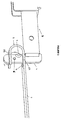
- FIG 1. This structure is made up of at least one upright and two sleepers extending on the same side of said amount. One of sleepers, is at its end, free for the attachment to device 1 while the other of cross members, by its free end, in abutment generally on a vertical wall of the construction 11.
- one of the sleepers in this case the lower sleeper, comes in support at a point P of construction 11 to prevent the effect of the tilting torque exerted on said structure 3, in particular when loaded by materials and / or roofers.
- the first one crosspiece in this case the upper crosspiece, comprises meanwhile at its free end a hooking finger 4 extending substantially orthogonally to said crosspiece towards the lower end of the amount of the structure 3.
- This hooking finger 4 substantially straight is adapted to cooperate with the device 1.
- the scaffolding structure 3 allows, in itself known, to delimit a path of circulation of stakeholders, this circulation can be carried out in safe thanks to the presence of a guardrail (not shown) consisting of boards supported by uprights generally fitted with hooks of said structure.
- the hanging finger 4 can be carried by a mounted arm telescopically on the upper cross member of said structure 3, this cross member being itself carried by the amount of the structure.
- the device 1 consists of a body 7 arranged to be fixed to an element 2 of the construction by suitable fixing means. Variants of realization of this body 7 have been shown in the figures 1 to 5 depending on the construction element 2 on which this body 7 must be fixed.
- the fixing means can also meanwhile they affect a large number of forms. They can be constituted by simple organs of fixing such as screws, nails or the like, or by more complex anchoring devices such as sockets or other.
- This body 7 is provided with a hook 8 affecting the shape of minus one open loop towards element 2 of construction.
- This hook 8 comprises at least two openings or lights 9, 10 superimposed formed in correspondence and forming a substantially guide path vertical for axial insertion from above, i.e. from the top of the guide path, with your finger attachment 4 of the scaffolding structure 3 to inside said openings 9, 10.
- these openings 9 and 10 prevent the pivoting of the attachment finger 4 of the scaffolding structure 3 in the direction of tilting of the scaffolding structure 3 by lifting towards element 2 of construction.
- Such a tilt is represented by the arrow F in figure 1.
- the advantage of such a solution lies in its simplicity. Indeed, the mere fact of having formed two openings 9 and 10 in correspondence allows safely avoid any risk of accident such as set out above.
- At least one of the openings 9, 10 of the hook 8 of the device is shaped to prevent rotation of the attachment finger 4 of the structure scaffolding 3 around its longitudinal axis.
- the catching finger consisting of a simple plate has a thickness such that when introduced inside the lower opening 10 of the hook 8, it can no longer be rotated around its longitudinal axis, the edges of the opening 10 enclosing the plate constituting the attachment finger 4.
- the openings 9, 10 are shaped so that that the upper opening 9 is delimited by a section closed while the lower opening 10 is delimited by an open section towards construction 11., so as to allow, when moving in the direction F 'of the scaffolding structure corresponding to a opposite direction of tilting of the scaffolding structure 3 by lifting towards element 2 of construction, freedom of movement of the finger 4.
- This freedom of movement of the finger 4 is necessary for the support of the scaffolding structure 3 on construction 11 in especially when this scaffolding structure 3 does not has no means for adjusting its fulcrum on construction 11.
- Such realization of openings therefore allows the use of the attachment device 1 for scaffolding structures and constructions of varied design without complicating the design of this device 1.
- At least one of the openings 9, 10 of the hook 8 of the device 1 is of length greater than the section of the attachment finger 4 of the scaffolding structure for allow, after insertion of the hooking finger 4 to inside one of the openings 9, 10, a translation of finger 4 inside this opening following a direction orthogonal to the axis of insertion of the finger in said opening and in the direction of a removal of the finger 4 of building element 2.
- the upper opening 9 of the hook 8 is longer than the section of the finger attachment 4.
- This opening 9 comprises at least one enlarged portion 9A for the passage of a bulge 5 or a latching finger boss 4.
- the attachment finger 4 of the structure scaffolding 3 may also include at least one bore 6 for the passage of an organ (not shown), such as a pin, for locking the locking finger 4 to the interior of said openings 9, 10 of the hook 8 of the device 1.
- This hole 6 is more particularly shown in Figure 3.
- the pin in position locked, extends orthogonally to the guide path formed by and between the openings 9 and 10.
- the opening 9 of the hook 8 of length greater than the section of the attachment finger 4 of the structure of scaffolding 3 substantially affects the shape of a double lock.
- this opening 9 can be envisaged.
- the hook 8 of device 1 substantially affects the shape of a C to concavity turned towards the construction element 2.
- the upper branch 8A of C is arranged substantially in the extension of the body 7 of the device 1 while the lower branch 8B of C has a terminal end free.
- the openings 9, 10 of the hook 8 are formed, in correspondence, respectively in the upper branch 8A and the lower branch 8B of the hook 8, the opening 10 of the lower branch 8B being directed towards the element 2 of construction. Therefore, the free end of the lower leg 8B of hook 8 substantially affects the shaped like a fork, the space left free between said branches of the fork constituting the opening 10.
- connection zone between the lower and upper branches of the hook is here shown as a curved portion.
- this portion could, equivalently, be a straight portion.
- At least two attachment devices 1 according to the invention are positioned and fixed on elements of construction.
- the scaffolding structure 3 previously at least partially mounted, is then hung on said devices thanks to the hanging pins 4 carried by the arms forming crosspieces of said structure, as as shown in figure 1.
- the elements complementary such as railing elements, elements floor, etc.
- the scaffolding structure is at this moment ready to receive a speaker and / or charges.
Landscapes
- Engineering & Computer Science (AREA)
- Architecture (AREA)
- Mechanical Engineering (AREA)
- Civil Engineering (AREA)
- Structural Engineering (AREA)
- Hooks, Suction Cups, And Attachment By Adhesive Means (AREA)
- Emergency Lowering Means (AREA)
- Movable Scaffolding (AREA)
- Electric Cable Installation (AREA)
- Clamps And Clips (AREA)
- Gripping Jigs, Holding Jigs, And Positioning Jigs (AREA)
- Mutual Connection Of Rods And Tubes (AREA)
- Helmets And Other Head Coverings (AREA)
- Tents Or Canopies (AREA)
Abstract
Description
La présente invention concerne un dispositif fixé, de préférence de façon permanente, à un élément, tel qu'un élément de charpente ou un mur, d'une construction, pour l'accrochage d'une structure d'échafaudage destinée en particulier à faciliter la réalisation ou l'entretien de toiture d'une quelconque construction ainsi qu'une structure d'échafaudage apte à coopérer avec un tel dispositif.The present invention relates to a fixed device, preferably permanently, to an item, such as structural element or wall, of a construction, for the attachment of a scaffolding structure intended for particular to facilitate the realization or maintenance of roof of any construction as well as scaffolding structure able to cooperate with such device.
L'invention concerne plus particulièrement les dispositifs adaptés pour recevoir une structure d'échafaudage avec appui de cette structure en un point de la construction pour empêcher l'effet du couple de basculement s'exerçant sur ladite structure, en particulier lorsqu'elle est chargée par des matériaux et/ou des intervenants en toiture.The invention relates more particularly to devices adapted to receive a scaffolding structure with support of this structure at a point in the construction to prevent the effect of the tilting moment acting on said structure, in particular when it is loaded by materials and / or stakeholders in roofing.
Un dispositif d'amarrage ou d'ancrage destiné à recevoir une telle structure d'échafaudage est notamment décrit dans les documents FR-A-2.245.213 et FR-A-2.307.100 du présent inventeur. A mooring or anchoring device intended to receive such a scaffolding structure is particularly described in documents FR-A-2.245.213 and FR-A-2.307.100 of this inventor.
Dans le document FR-A-2.245.213, l'organe d'ancrage comporte une embase propre à être fixée à un chevron et un trou unique propre à recevoir un doigt d'accrochage de la structure d'échafaudage. Le trou est ménagé sur un talon prolongeant ladite embase, talon et embase étant disposés dans l'axe du chevron. L'inconvénient majeur d'un tel dispositif d'ancrage réside dans l'impossibilité d'empêcher, au moyen d'un tel dispositif d'ancrage, le basculement de la structure d'échafaudage par soulèvement en direction de l'élément de la construction. Un tel basculement peut notamment survenir en cas de mauvais temps lorsqu'un vent violent agit sur la structure d'échafaudage. De la même manière, il n'est pas possible, au moyen d'un tel dispositif d'ancrage, d'empêcher la rotation de la structure d'échafaudage autour de l'axe formé d'une part par son point d'appui sur l'élément de la construction, d'autre part par son point d'ancrage sur le dispositif d'ancrage. Il en résulte là encore des risques d'accident en cas de vent violent. Ces mêmes inconvénients s'appliquent au dispositif d'ancrage décrit dans le brevet FR-A-2.245.213.In document FR-A-2.245.213, the anchoring member has a base suitable for being fixed to a rafter and a single hole suitable for receiving a hooking finger of the scaffolding structure. The hole is made on a heel extending said base, heel and base being arranged in the chevron axis. The major disadvantage of such anchoring device lies in the impossibility prevent, by means of such an anchoring device, the tilting of the scaffolding structure by lifting towards the building element. Such tipping can occur in particular in bad weather when a strong wind acts on the scaffolding structure. Likewise, it is not possible, by means of a such anchoring device, to prevent rotation of the scaffolding structure around the axis formed on the one hand by its fulcrum on the building element, secondly by its anchor point on the device anchor. Again, this results in accident risks in strong winds. These same drawbacks apply to the anchoring device described in the patent FR-A-2.245.213.
Dans le brevet français FR-A-2.349.706, diverses configurations d'un dispositif d'ancrage sont représentées. Dans une première forme de réalisation, le dispositif d'ancrage comporte une embase pourvue de deux ouvertures destinées à recevoir un organe d'accrochage d'une structure d'échafaudage. Cet organe d'accrochage affecte la forme d'un crochet formant une boucle ouverte dans une direction opposée à la construction. L'inconvénient d'une telle solution réside d'abord dans la difficulté d'accrochage de la structure d'échafaudage du fait que le crochet d'accrochage de cette structure doit être fixé par le dessous au dispositif d'ancrage après orientation angulaire précise de la structure d'échafaudage, ce qui nécessite dextérité et force physique de l'opérateur. Par ailleurs, une telle solution présente les mêmes risques de soulèvement de la structure d'échafaudage que ceux décrits précédemment dans le cadre des dispositifs des brevets FR-A-2.245.213 et FR-A-2.307.100 précités.In French patent FR-A-2,349,706, various configurations of an anchoring device are shown. In a first embodiment, the device anchor has a base provided with two openings intended to receive a fastening member of a structure scaffolding. This hooking member affects the shape of a hook forming an open loop in one direction opposed to construction. The downside of such solution lies first in the difficulty of hanging the scaffolding structure of the fact that the hook of this structure must be fixed by the bottom to anchor after angular orientation precise scaffolding structure, which requires operator dexterity and physical strength. Otherwise, such a solution presents the same risks of lifting the scaffolding structure as those described previously in the context of the patent arrangements FR-A-2.245.213 and FR-A-2,307,100 cited above.
Dans le brevet FR-A-1.482.220, il est décrit un crochet de sécurité pour gouttière apte à supporter un chandelier qui constitue un garde-fou. Ce chandelier destiné à être fixé au crochet de sécurité, ne vient pas en appui sur la construction et ne comporte donc pas les avantages inhérents à ce type de structure d'échafaudage. En effet, le chandelier ne comporte pas de plate-forme de circulation. Par ailleurs, en cas d'appui sur ce chandelier d'un homme ou d'une charge, on provoque un effort important sur le crochet de sécurité générant soit un arrachement de ce dernier, soit un pliage du corps de ce dernier.In patent FR-A-1,482,220, a hook is described. safety for gutter able to support a candlestick which constitutes a safeguard. This candlestick intended to be fixed with the safety hook, does not come to rest on the construction and therefore does not have the benefits inherent in this type of scaffolding structure. Indeed, the candlestick does not have a platform circulation. Furthermore, if this candlestick is pressed of a man or a load, we cause a significant effort on the safety hook generating either a tearing of the latter, or a folding of the latter's body.
Par ailleurs, le crochet de sécurité est constitué d'une embase terminée par une boucle fermée de telle sorte que le coût d'un tel crochet est relativement onéreux et la fabrication plus compliquée que celle du dispositif d'ancrage objet de la présente invention. Enfin, une telle structure du crochet de sécurité ne permet pas un positionnement angulaire variable du chandelier en fonction de la construction. Un tel inconvénient vaut également pour le dispositif décrit dans le brevet FR-A-2.728.923.Furthermore, the safety hook consists of a manifold terminated by a closed loop so that the cost of such a hook is relatively expensive and the more complicated than the device anchor object of the present invention. Finally, such safety hook structure does not allow a variable angular positioning of the candlestick as a function construction. Such a disadvantage also applies to the device described in patent FR-A-2,728,923.
Le but de la présente invention est donc de pallier les inconvénients précités en proposant un dispositif pour l'accrochage d'une structure d'échafaudage qui empêche, de manière sûre, la structure d'échafaudage à la fois de basculer par soulèvement en direction de l'élément de la construction qui porte cette structure et de tourner autour d'un axe sensiblement vertical passant par le point d'appui de la structure sur la construction et le point d'accrochage de la structure au dispositif tout en autorisant une possibilité de positionnement angulaire variable de la structure d'échafaudage sur le dispositif. The purpose of the present invention is therefore to overcome the disadvantages mentioned above by proposing a device for the attachment of a scaffolding structure which prevents, safely, the scaffolding structure of both tilt by lifting towards the element of the construction that carries this structure and turn around a substantially vertical axis passing through the fulcrum of structure on construction and point of attachment of the structure to the device while allowing a possibility of angular positioning variable of the scaffolding structure on the device.
Un autre but de la présente invention est de proposer un dispositif d'accrochage d'une structure d'échafaudage dont la conception permet, pour des constructions quelconques, la réception de structures d'échafaudage de dimension variable et dont le point d'appui ne présente pas forcément un positionnement réglable du fait des possibilités d'adaptation intrinsèques au dispositif d'accrochage.Another object of the present invention is to provide a attachment device for a scaffolding structure, the design allows, for any construction, the reception of dimension scaffolding structures variable and whose point of support does not necessarily have adjustable positioning due to the possibilities intrinsic adaptation to the hanging device.
Un autre but de la présente invention est de proposer un dispositif d'accrochage d'une structure d'échafaudage de conception simple, de faible encombrement, de coût réduit adapté pour coopérer avec une structure d'échafaudage dont le doigt d'accrochage est également de conception simple.Another object of the present invention is to provide a attachment device for a scaffolding structure simple design, small footprint, low cost adapted to cooperate with a scaffolding structure of which the hooking finger is also simple in design.
A cet effet, l'invention a pour objet un dispositif fixé, de préférence de façon permanente, à un élément, tel qu'un élément de charpente ou un mur, d'une construction pour l'accrochage d'une structure d'échafaudage avec appui de cette structure en au moins un point de la construction pour empêcher l'effet du couple du basculement s'exerçant sur ladite structure, en particulier lorsqu'elle est chargée par des matériaux et/ou des intervenants en toiture, cette structure possédant au moins un doigt d'accrochage adapté à coopérer avec le dispositif, caractérisé en ce que le dispositif est constitué d'un corps propre à être fixé à l'élément de construction, ce corps étant muni d'un crochet affectant la forme d'au moins une boucle ouverte en direction de l'élément de construction, ce crochet comportant au moins deux ouvertures superposées formant un chemin de guidage sensiblement vertical pour l'introduction axiale par le dessus du doigt d'accrochage de la structure d'échafaudage à l'intérieur desdites ouvertures, l'ouverture supérieure étant délimitée par une section fermée tandis que l'ouverture inférieure est délimitée par une section ouverte en direction de la construction, lesdites ouvertures coopérant entre elles pour empêcher le pivotement du doigt d'accrochage de la structure d'échafaudage dans le sens d'un basculement de la structure d'échafaudage par soulèvement en direction de l'élément de construction et permettre, dans le sens opposé une liberté de mouvement du doigt d'accrochage nécessaire pour la mise en appui de la structure d'échafaudage sur la construction.To this end, the subject of the invention is a fixed device, preferably permanently, to an item, such as structural element or wall, of a construction for the attachment of a scaffolding structure with support this structure in at least one point of the construction to prevent the effect of the tilting torque acting on said structure, in particular when it is loaded by materials and / or stakeholders in roof, this structure having at least one finger attachment adapted to cooperate with the device, characterized in that the device consists of a body suitable for being attached to the building element, this body being provided with a hook affecting the shape of at least an open loop towards the element of construction, this hook comprising at least two superimposed openings forming a guide path substantially vertical for axial insertion through the above the attachment finger of the scaffolding structure inside said openings, the upper opening being bounded by a closed section while the lower opening is delimited by a section open towards construction, said openings cooperating with each other to prevent the pivoting of the fastening finger of the structure scaffolding in the direction of tilting of the structure scaffolding by lifting towards the element of construction and allow, in the opposite direction a freedom movement of the hooking finger required for setting to support the scaffolding structure on the construction.
Grâce à cette conception du dispositif d'accrochage, tout risque d'accident, y compris en cas de vent violent, est évité et ce malgré une grande capacité d'adaptation du dispositif à l'égard de la structure d'échafaudage à recevoir ou de la construction à équiper.Thanks to this design of the hanging device, everything risk of accident, including in strong winds, is avoided despite a great adaptability of the device with respect to the scaffolding structure to receive or construction to equip.
Selon une forme de réalisation préférée de l'invention, au moins l'une des ouvertures du crochet du dispositif est conformée pour empêcher, après introduction d'un doigt d'accrochage d'une structure d'échafaudage à l'intérieur de ladite ouverture, la rotation de ce doigt d'accrochage autour de son axe longitudinal.According to a preferred embodiment of the invention, at minus one of the device hook openings is shaped to prevent, after insertion of a finger for hanging a scaffolding structure inside said opening, the rotation of this latching finger around its longitudinal axis.
L'invention a encore pour objet une structure d'échafaudage du type possédant au moins un doigt d'accrochage pour l'accrochage de la structure à un dispositif fixé, de préférence de façon permanente, à un élément, tel qu'un élément de charpente ou un mur, d'une construction, avec appui de cette structure en au moins un point de la construction pour empêcher l'effet du couple de basculement s'exerçant sur ladite structure, en particulier lorsqu'elle est chargée par des matériaux et/ou des intervenants en toiture, caractérisée en ce que le doigt d'accrochage est agencé pour coopérer avec des ouvertures du dispositif constitué d'un corps propre à être fixé à l'élément de construction, ce corps étant muni d'un crochet affectant la forme d'au moins une boucle ouverte en direction de l'élément de construction, ce crochet comportant au moins deux ouvertures superposées, formant un chemin de guidage sensiblement vertical pour l'introduction axiale par le dessus du doigt d'accrochage de la structure d'échafaudage à l'intérieur desdites ouvertures, l'ouverture supérieure étant délimitée par une section fermée tandis que l'ouverture inférieure est délimitée par une section ouverte en direction de la construction pour empêcher le pivotement du doigt d'accrochage de la structure d'échafaudage dans le sens d'un basculement de la structure d'échafaudage par soulèvement en direction de l'élément de construction et permettre, dans le sens opposé une liberté de mouvement du doigt d'accrochage nécessaire pour la mise en appui de la structure d'échafaudage sur la construction.The invention also relates to a scaffolding structure of the type having at least one latching finger for the attachment of the structure to a fixed device, preferably permanently, to an item, such as structural element or wall, of a construction, with support of this structure in at least one point of the construction to prevent the effect of tilting torque acting on said structure, in particular when it is loaded by materials and / or stakeholders in roof, characterized in that the catching finger is arranged to cooperate with openings of the device consisting of a body suitable for being fixed to the element of construction, this body being provided with a hook affecting the forms at least one open loop towards the building element, this hook comprising at least two superimposed openings, forming a guide path substantially vertical for axial insertion through the above the attachment finger of the scaffolding structure inside said openings, the upper opening being bounded by a closed section while the lower opening is delimited by a section open towards construction to prevent the pivoting of the fastening finger of the structure scaffolding in the direction of tilting of the structure scaffolding by lifting towards the element of construction and allow, in the opposite direction a freedom movement of the hooking finger required for setting to support the scaffolding structure on the construction.
L'invention sera bien comprise à la lecture de la
description suivante d'exemples de réalisation, en
référence aux dessins annexés dans lesquels :
Le dispositif, objet de l'invention, représenté sous la
référence générale 1, est destiné à être fixé à un élément
2 d'une construction 11. Cet élément 2 de construction peut
être un mur ou un élément de charpente de ladite
construction 11. Dans les exemples de réalisation
représentés, l'élément 2 de construction est constitué dans
la figure 1 par un chevron et dans la figure 4 par un mur.The device, object of the invention, represented under the
general reference 1, is intended to be fixed to an
A ce dispositif 1 est accrochée une structure d'échafaudage
3 qui peut être une structure déjà connue en soi du type de
celle représentée dans le brevet FR-A-2.245.213 ou une
structure à créer. Un exemple de réalisation d'une telle
structure est représenté à la figure 1. Cette structure est
constituée d'au moins un montant et deux traverses
s'étendant d'un même côté dudit montant. L'une des
traverses, est à sa partie terminale, libre pour
l'accrochage au dispositif 1 tandis que l'autre des
traverses vient, par son extrémité libre, en butée
généralement sur une paroi verticale de la construction 11.
Dans l'exemple représenté à la figure 1, l'une des
traverses, en l'occurrence la traverse inférieure, vient en
appui en un point P de la construction 11 pour empêcher
l'effet du couple du basculement s'exerçant sur ladite
structure 3, en particulier lorsqu'elle est chargée par des
matériaux et/ou des intervenants en toiture. La première
traverse, en l'occurrence la traverse supérieure, comporte
quant à elle à son extrémité libre un doigt d'accrochage 4
s'étendant sensiblement orthogonalement à ladite traverse
en direction de l'extrémité inférieure du montant de la
structure 3. Ce doigt d'accrochage 4 sensiblement
rectiligne est adapté à coopérer avec le dispositif 1.To this device 1 is hung a
La structure 3 d'échafaudage permet, de manière en soi
connue, de délimiter un chemin de circulation des
intervenants, cette circulation pouvant être effectuée en
toute sécurité grâce à la présence d'un garde-corps (non
représenté) constitué de planches supportées par les
montants généralement équipés de crochets de ladite
structure.The
Le doigt d'accrochage 4 peut être porté par un bras monté
de manière télescopique sur la traverse supérieure de
ladite structure 3, cette traverse étant elle-même portée
par le montant de la structure.The hanging
Le dispositif 1 est quant à lui constitué d'un corps 7
agencé pour être fixé à un élément 2 de la construction par
des moyens de fixation appropriés. Des variantes de
réalisation de ce corps 7 ont été représentées aux figures
1 à 5 en fonction de l'élément de construction 2 sur lequel
ce corps 7 doit être fixé. Les moyens de fixation peuvent
également quant à eux affecter un grand nombre de formes.
Ils peuvent être constitués par de simples organes de
fixation tels que vis, clous ou similaires, ou par des
dispositifs d'ancrage plus complexes tels que douilles ou
autre.The device 1 consists of a
Ce corps 7 est muni d'un crochet 8 affectant la forme d'au
moins une boucle ouverte en direction de l'élément 2 de
construction. Ce crochet 8 comporte au moins deux
ouvertures ou lumières 9, 10 superposées ménagées en
correspondance et formant un chemin de guidage sensiblement
vertical pour l'introduction axiale par le dessus, c'est-à-dire
par le haut du chemin de guidage, du doigt
d'accrochage 4 de la structure d'échafaudage 3 à
l'intérieur desdites ouvertures 9, 10. Comme le montre la
figure 1, ces ouvertures 9 et 10 empêchent le pivotement du
doigt d'accrochage 4 de la structure d'échafaudage 3 dans
le sens d'un basculement de la structure d'échafaudage 3
par soulèvement en direction de l'élément 2 de
construction. Un tel basculement est représenté par la
flèche F dans la figure 1. L'intérêt d'une telle solution
réside dans sa simplicité. En effet, le seul fait d'avoir
ménagé deux ouvertures 9 et 10 en correspondance permet
d'éviter de manière sûre tout risque d'accident tel
qu'exposé ci-dessus. This
Par ailleurs, au moins l'une des ouvertures 9, 10 du
crochet 8 du dispositif est conformée pour empêcher la
rotation du doigt d'accrochage 4 de la structure
d'échafaudage 3 autour de son axe longitudinal. En effet,
comme le montrent les figures 3 et 4, le doigt d'accrochage
constitué par une simple plaque présente une épaisseur
telle que, lorsqu'il est introduit à l'intérieur de
l'ouverture inférieure 10 du crochet 8, il ne peut plus
être entraíné en rotation autour de son axe longitudinal,
les bords de l'ouverture 10 enserrant la plaque
constitutive du doigt d'accrochage 4.Furthermore, at least one of the
Enfin, les ouvertures 9, 10 sont conformées de telle sorte
que l'ouverture supérieure 9 est délimitée par une section
fermée tandis que l'ouverture inférieure 10 est délimitée
par une section ouverte en direction de la construction
11., de manière à permettre, lors d'un déplacement dans le
sens F' de la structure d'échafaudage correspondant à un
sens opposé à un basculement de la structure d'échafaudage
3 par soulèvement en direction de l'élément 2 de
construction, une liberté de mouvement du doigt
d'accrochage 4. Cette liberté de mouvement du doigt
d'accrochage 4 est nécessaire pour la mise en appui de la
structure d'échafaudage 3 sur la construction 11 en
particulier lorsque cette structure d'échafaudage 3 ne
comporte pas de moyens de réglage de son point d'appui sur
la construction 11. Une telle réalisation des ouvertures
permet donc l'utilisation du dispositif 1 d'accrochage pour
des structures d'échafaudage et des constructions de
conception variée sans compliquer pour autant la conception
de ce dispositif 1.Finally, the
Au moins l'une des ouvertures 9, 10 du crochet 8 du
dispositif 1 est de longueur supérieure à la section du
doigt d'accrochage 4 de la structure d'échafaudage pour
permettre, après introduction du doigt d'accrochage 4 à
l'intérieur de l'une des ouvertures 9, 10, une translation
du doigt 4 à l'intérieur de cette ouverture suivant une
direction orthogonale à l'axe d'introduction du doigt dans
ladite ouverture et dans le sens d'un éloignement du doigt
4 de l'élément de construction 2. Dans les exemples
représentés aux figures 3 et 4, l'ouverture supérieure 9 du
crochet 8 est de longueur supérieure à la section du doigt
d'accrochage 4. Cette ouverture 9 comporte au moins une
portion élargie 9A pour le passage d'un renflement 5 ou
d'un bossage du doigt d'accrochage 4. Cette portion élargie
9A est ménagée dans ladite ouverture 9 en un emplacement
permettant, une fois le doigt d'accrochage 4 introduit et
translaté dans ladite ouverture 9, un décalage axial entre
le renflement 5 du doigt d'accrochage 4 et la portion
élargie 9A de ladite ouverture 9 de manière à empêcher
toute sortie intempestive du doigt d'accrochage 4 de ladite
ouverture 9. Toutefois, pour parfaire la sécurité d'une tel
accrochage, le doigt d'accrochage 4 de la structure
d'échafaudage 3 peut encore comporter au moins un perçage 6
pour le passage d'un organe (non représenté), tel qu'une
goupille, de verrouillage du doigt d'accrochage 4 à
l'intérieur desdites ouvertures 9, 10 du crochet 8 du
dispositif 1. Ce perçage 6 est plus particulièrement
représenté à la figure 3. La goupille, en position
verrouillée, s'étend orthogonalement au chemin de guidage
formé par les ouvertures 9 et 10 et entre ces dernières. Il
est à noter que ces aménagements du doigt d'accrochage 4,
comportant au moins un perçage 6 et un renflement 5,
rendent la structure d'échafaudage, destinée à coopérer
avec le dispositif d'accrochage, nouvelle.At least one of the
Dans les exemples représentés aux figures 1 à 5,
l'ouverture 9 du crochet 8 de longueur supérieure à la
section du doigt d'accrochage 4 de la structure
d'échafaudage 3 affecte sensiblement la forme d'un trou de
serrure double. Toutefois, d'autres formes de réalisation
de cette ouverture 9 peuvent être envisagées.In the examples shown in Figures 1 to 5,
the opening 9 of the
De même, dans tous les exemples représentés, le crochet 8
du dispositif 1 affecte sensiblement la forme d'un C à
concavité tournée vers l'élément 2 de construction. La
branche supérieure 8A du C est disposée sensiblement dans
le prolongement du corps 7 du dispositif 1 tandis que la
branche inférieure 8B du C présente une extrémité terminale
libre. Les ouvertures 9, 10 du crochet 8 sont ménagées, en
correspondance, respectivement dans la branche supérieure
8A et la branche inférieure 8B du crochet 8, l'ouverture 10
de la branche inférieure 8B étant dirigée vers l'élément 2
de construction. De ce fait, l'extrémité libre de la
branche inférieure 8B du crochet 8 affecte sensiblement la
forme d'une fourchette, l'espace laissé libre entre
lesdites branches de la fourchette constituant l'ouverture
10.Similarly, in all the examples shown, the
Bien évidemment, il est possible de modifier la forme de
réalisation de ce crochet 8. Ainsi, la zone de liaison
entre les branches inférieure et supérieure du crochet est
ici représentée sous forme d'une portion courbe. Toutefois,
cette portion pourrait, de manière équivalente, être une
portion rectiligne.Obviously, it is possible to modify the form of
realization of this
Grâce à un tel dispositif d'accrochage et en particulier
grâce à la conception du crochet 8 de ce dispositif, tout
risque de basculement dans le sens de la flèche F
conformément à la figure 1 et tout risque d'entraínement en
rotation de la structure d'échafaudage 3 autour d'un axe
sensiblement vertical passant par son point d'appui P sur
la construction et son point d'accrochage au dispositif est
empêché malgré une possibilité de liberté de mouvement du
doigt d'accrochage de la structure d'échafaudage nécessaire
à la mise en appui de cette structure lors de son
accrochage au dispositif. Un tel dispositif limite donc de
manière importante les risques d'accident sans compliquer
ni la réalisation du dispositif, ni la réalisation de la
structure d'échafaudage destinée à coopérer avec ce
dernier. Thanks to such a hanging device and in particular
thanks to the design of the
En pratique, au moins deux dispositifs d'accrochage 1 selon
l'invention sont positionnés et fixés sur des éléments de
construction. La structure d'échafaudage 3, préalablement
au moins partiellement montée, est alors accrochée sur
lesdits dispositifs grâce aux doigts d'accrochage 4 portés
par les bras formant traverses de ladite structure, comme
le montre la figure 1. Une fois la structure d'échafaudage
positionnée, il est alors possible de disposer les éléments
complémentaires tels qu'éléments de garde-corps, éléments
de plancher, etc. La structure d'échafaudage est à ce
moment prête à recevoir un intervenant et/ou des charges.In practice, at least two attachment devices 1 according to
the invention are positioned and fixed on elements of
construction. The
Claims (10)
caractérisé en ce que le dispositif (1) est constitué d'un corps (7) propre à être fixé à l'élément (2) de construction, ce corps (7) étant muni d'un crochet (8) affectant la forme d'au moins une boucle ouverte en direction de l'élément (2) de construction, ce crochet (8) comportant au moins deux ouvertures (9, 10) superposées formant un chemin de guidage sensiblement vertical pour l'introduction axiale par le dessus du doigt d'accrochage (4) de la structure d'échafaudage (3) à l'intérieur desdites ouvertures (9, 10), l'ouverture supérieure (9) étant délimitée par une section fermée tandis que l'ouverture inférieure (10) est délimitée par une section ouverte en direction de la construction (11), lesdites ouvertures (9, 10) coopérant entre elles pour empêcher le pivotement du doigt d'accrochage (4) de la structure d'échafaudage (3) dans le sens (F) d'un basculement de la structure d'échafaudage (3) par soulèvement en direction de l'élément (2) de construction et permettre, dans le sens opposé (F') une liberté de mouvement du doigt d'accrochage (4) nécessaire pour la mise en appui de la structure d'échafaudage (3) sur la construction (11).Device (1) fixed, preferably permanently, to an element (2), such as a frame element or a wall, of a construction (11) for the attachment of a structure (3) of scaffolding with support of this structure (3) at at least one point (P) of the construction (11) to prevent the effect of the tilting torque exerted on said structure (3), in particular when it is loaded by materials and / or stakeholders on the roof, this structure (3) having at least one attachment finger (4) adapted to cooperate with the device (1),
characterized in that the device (1) consists of a body (7) suitable for being fixed to the construction element (2), this body (7) being provided with a hook (8) affecting the shape of '' at least one open loop in the direction of the building element (2), this hook (8) comprising at least two superimposed openings (9, 10) forming a substantially vertical guide path for axial insertion from above attachment finger (4) of the scaffolding structure (3) inside said openings (9, 10), the upper opening (9) being delimited by a closed section while the lower opening (10) is delimited by a section open in the direction of construction (11), said openings (9, 10) cooperating with each other to prevent pivoting of the latching finger (4) of the scaffolding structure (3) in the direction ( F) tilting of the scaffolding structure (3) by lifting in the direction of the construction element (2) ion and allow, in the opposite direction (F ') freedom of movement of the latching finger (4) necessary for the support of the scaffolding structure (3) on the construction (11).
caractérisé en ce qu'au moins l'une des ouvertures (9, 10) du crochet (8) du dispositif est conformée pour empêcher, après introduction d'un doigt d'accrochage (4) d'une structure d'échafaudage (3) à l'intérieur de ladite ouverture la rotation de ce doigt d'accrochage (4) autour de son axe longitudinal.Device according to claim 1,
characterized in that at least one of the openings (9, 10) of the hook (8) of the device is shaped to prevent, after introduction of a hooking finger (4) from a scaffolding structure (3 ) inside said opening the rotation of this latching finger (4) about its longitudinal axis.
caractérisé en ce qu'au moins l'une des ouvertures (9, 10) du crochet (8) du dispositif (1) est de longueur supérieure à la section du doigt d'accrochage (4) destiné à coopérer avec le dispositif pour permettre, après introduction du doigt d'accrochage (4) à l'intérieur de ladite ouverture (9, 10), une translation du doigt (4) à l'intérieur de ladite ouverture suivant une direction orthogonale à l'axe d'introduction du doigt dans ladite ouverture et dans le sens d'un éloignement du doigt (4) de l'élément (2) de construction.Device according to either of Claims 1 and 2,
characterized in that at least one of the openings (9, 10) of the hook (8) of the device (1) is of greater length than the section of the hooking finger (4) intended to cooperate with the device to allow , after introduction of the attachment finger (4) inside said opening (9, 10), a translation of the finger (4) inside said opening in a direction orthogonal to the axis of introduction of the finger in said opening and in the direction of a separation of the finger (4) from the construction element (2).
caractérisé en ce que l'ouverture (9) du crochet (8) de dimension supérieure à la section du doigt d'accrochage (4) de la structure d'échafaudage (3) comporte au moins une portion élargie (9A) pour le passage d'un renflement (5) du doigt d'accrochage (4), cette portion élargie (9A) étant ménagée dans ladite ouverture (9) en un emplacement permettant, une fois le doigt d'accrochage (4) introduit et déplacé en translation dans ladite ouverture (9), un décalage axial entre renflement (5) du doigt d'accrochage (4) et portion élargie (9A) de ladite ouverture (9) de manière à empêcher toute sortie intempestive du doigt d'accrochage (4) de ladite ouverture (9).Device according to claim 3,
characterized in that the opening (9) of the hook (8) of dimension greater than the section of the hooking finger (4) of the scaffolding structure (3) comprises at least one enlarged portion (9A) for the passage a bulge (5) of the catching finger (4), this enlarged portion (9A) being formed in said opening (9) in a location allowing, once the catching finger (4) introduced and moved in translation in said opening (9), an axial offset between bulge (5) of the hooking finger (4) and enlarged portion (9A) of said opening (9) so as to prevent any untimely exit of the hooking finger (4) of said opening (9).
caractérisé en ce que l'ouverture (9) du crochet (8) de dimension supérieure à la section du doigt d'accrochage (4) de la structure d'échafaudage (3) affecte sensiblement la forme d'un trou de serrure double.Device according to one of claims 3 and 4,
characterized in that the opening (9) of the hook (8) of dimension greater than the section of the hooking finger (4) of the scaffolding structure (3) substantially affects the shape of a double keyhole.
caractérisé en ce que le crochet (8) affecte sensiblement la forme d'un C à concavité tournée vers l'élément de construction (2), la branche supérieure (8A) du C étant disposée dans le prolongement du corps (7) du dispositif (1) tandis que la branche inférieure (8B) du C présente une extrémité terminale libre.Device (1) according to one of claims 1 to 5,
characterized in that the hook (8) substantially affects the shape of a C with a concavity facing the building element (2), the upper branch (8A) of the C being arranged in the extension of the body (7) of the device (1) while the lower branch (8B) of C has a free terminal end.
caractérisé en ce que les ouvertures (9, 10) du crochet (8) sont ménagées en correspondance, respectivement dans la branche inférieure (8B) et la branche supérieure (8A) du crochet (8), l'ouverture (10) de la branche inférieure (8B) étant ouverte en direction de l'élément de construction (2).Device according to claim 6,
characterized in that the openings (9, 10) of the hook (8) are arranged in correspondence, respectively in the lower branch (8B) and the upper branch (8A) of the hook (8), the opening (10) of the lower branch (8B) being open towards the building element (2).
caractérisée en ce que le doigt d'accrochage (4) est agencé pour coopérer avec des ouvertures (9, 10) du dispositif (1) constitué d'un corps (7) propre à être fixé à l'élément (2) de construction, ce corps (7) étant muni d'un crochet (8) affectant la forme d'au moins une boucle ouverte en direction de l'élément (2) de construction, ce crochet (8) comportant au moins deux ouvertures (9, 10) superposées, formant un chemin de guidage sensiblement vertical pour l'introduction axiale par le dessus du doigt d'accrochage de la structure d'échafaudage (3) à l'intérieur desdites ouvertures (9, 10), l'ouverture supérieure (9) étant délimitée par une section fermée tandis que l'ouverture inférieure (10) est délimitée par une section ouverte en direction de la construction (11) pour empêcher le pivotement du doigt d'accrochage (4) de la structure d'échafaudage (3) dans le sens (F) d'un basculement de la structure d'échafaudage (3) par soulèvement en direction de l'élément (2) de construction et permettre, dans le sens opposé (F') une liberté de mouvement du doigt d'accrochage (4) nécessaire pour la mise en appui de la structure d'échafaudage (3) sur la construction (11).Structure (3) of scaffolding of the type having at least one hooking finger (4) for hooking the structure (3) to a device (1) fixed, preferably permanently, to an element (2) , such as a structural element or a wall, of a construction (11), with the support of this structure (3) at at least one point (P) of the construction (11) to prevent the effect of the torque tilting acting on said structure (3), in particular when it is loaded with materials and / or roofing workers,
characterized in that the attachment finger (4) is arranged to cooperate with openings (9, 10) of the device (1) consisting of a body (7) suitable for being fixed to the element (2) of construction , this body (7) being provided with a hook (8) affecting the shape of at least one open loop in the direction of the construction element (2), this hook (8) comprising at least two openings (9, 10) superimposed, forming a substantially vertical guide path for the axial insertion from above the attachment finger of the scaffolding structure (3) inside said openings (9, 10), the upper opening ( 9) being delimited by a closed section while the lower opening (10) is delimited by an open section in the direction of the construction (11) to prevent pivoting of the latching finger (4) of the scaffolding structure ( 3) in the direction (F) of a tilting of the scaffolding structure (3) by lifting in the direction of the el construction element (2) and allow, in the opposite direction (F '), a freedom of movement of the hooking finger (4) necessary for the support of the scaffolding structure (3) on the construction (11) .
caractérisée en ce que le doigt d'accrochage (4) de la structure d'échafaudage (3) comporte au moins un perçage (6) pour le passage d'un organe, tel qu'une goupille, de verrouillage du doigt d'accrochage (4) à l'intérieur desdites ouvertures (9, 10) du crochet (8) du dispositif (1).Scaffolding structure (3) according to claim 8,
characterized in that the catching finger (4) of the scaffolding structure (3) comprises at least one hole (6) for the passage of a member, such as a pin, for locking the catching finger (4) inside said openings (9, 10) of the hook (8) of the device (1).
caractérisée en ce que le doigt d'accrochage (4) de la structure d'échafaudage (3) comporte au moins un renflement (5) et en ce qu'au moins l'une des ouvertures du dispositif (1) comporte au moins une portion élargie (9A) pour le passage du renflement (5), cette portion élargie (9A) étant ménagée dans ladite ouverture (9) du dispositif en un emplacement permettant, une fois le doigt d'accrochage (4) introduit et déplacé en translation dans ladite ouverture (9), un décalage axial entre renflement (5) du doigt d'accrochage (4) et portion élargie (9A) de ladite ouverture (9) de manière à empêcher toute sortie intempestive du doigt d'accrochage (4) de ladite ouverture (9)Structure (3) of scaffolding according to one of claims 8 and 9,
characterized in that the catching finger (4) of the scaffolding structure (3) comprises at least one bulge (5) and in that at least one of the openings of the device (1) comprises at least one enlarged portion (9A) for the passage of the bulge (5), this enlarged portion (9A) being formed in said opening (9) of the device in a location allowing, once the latching finger (4) introduced and moved in translation in said opening (9), an axial offset between bulge (5) of the hooking finger (4) and enlarged portion (9A) of said opening (9) so as to prevent any untimely exit of the hooking finger (4) of said opening (9)
Applications Claiming Priority (2)
| Application Number | Priority Date | Filing Date | Title |
|---|---|---|---|
| FR9800435 | 1998-01-16 | ||
| FR9800435A FR2773834B1 (en) | 1998-01-16 | 1998-01-16 | DEVICE FOR HANGING A SCAFFOLDING STRUCTURE |
Publications (2)
| Publication Number | Publication Date |
|---|---|
| EP0930407A1 true EP0930407A1 (en) | 1999-07-21 |
| EP0930407B1 EP0930407B1 (en) | 2003-06-04 |
Family
ID=9521852
Family Applications (1)
| Application Number | Title | Priority Date | Filing Date |
|---|---|---|---|
| EP98403118A Expired - Lifetime EP0930407B1 (en) | 1998-01-16 | 1998-12-10 | Arrangement for securing a scaffold-structure |
Country Status (7)
| Country | Link |
|---|---|
| EP (1) | EP0930407B1 (en) |
| AT (1) | ATE242385T1 (en) |
| DE (1) | DE69815280T2 (en) |
| DK (1) | DK0930407T3 (en) |
| ES (1) | ES2200292T3 (en) |
| FR (1) | FR2773834B1 (en) |
| PT (1) | PT930407E (en) |
Cited By (1)
| Publication number | Priority date | Publication date | Assignee | Title |
|---|---|---|---|---|
| EP1482104A1 (en) * | 2003-05-28 | 2004-12-01 | Marc Antoine | Adjustable modular safety system for scaffold |
Families Citing this family (2)
| Publication number | Priority date | Publication date | Assignee | Title |
|---|---|---|---|---|
| DE102011102486B4 (en) * | 2011-05-24 | 2023-07-13 | Prototec Gesellschaft für individuelle Industrieplanungen mbH | Bracket for a scaffolding component or fall protection |
| DE202015104294U1 (en) * | 2015-08-14 | 2015-10-05 | Hakos Gmbh | An anchor plate for a side impact protection attachment system, and a side crash protection attachment system comprising an anchor plate and a hanger connectable to the plate |
Citations (5)
| Publication number | Priority date | Publication date | Assignee | Title |
|---|---|---|---|---|
| FR1482220A (en) | 1966-04-15 | 1967-05-26 | Frenehard & Michaux Ets | Safety hook for gutters |
| FR2245213A5 (en) | 1973-08-07 | 1975-04-18 | Goubaud Michel | Scaffolding for fixing to a roof - consists of a two armed bracket with anchor tie fixed to a rafter |
| FR2307100A2 (en) | 1973-08-07 | 1976-11-05 | Goubaud Michel | Scaffolding for roof repair and construction - consists of cantilever platform with safety barrier anchored to roof |
| FR2349706A1 (en) | 1976-04-27 | 1977-11-25 | Frenehard Et Michaux Sa Ets | Guard rail bracket support hook - consists of support and base pierced with hole and has finger hook forming part of bracket assembly |
| FR2728923A1 (en) | 1994-12-28 | 1996-07-05 | Giraud Roger | Protective device for workers on roof |
-
1998
- 1998-01-16 FR FR9800435A patent/FR2773834B1/en not_active Expired - Fee Related
- 1998-12-10 EP EP98403118A patent/EP0930407B1/en not_active Expired - Lifetime
- 1998-12-10 ES ES98403118T patent/ES2200292T3/en not_active Expired - Lifetime
- 1998-12-10 PT PT98403118T patent/PT930407E/en unknown
- 1998-12-10 DE DE69815280T patent/DE69815280T2/en not_active Expired - Fee Related
- 1998-12-10 DK DK98403118T patent/DK0930407T3/en active
- 1998-12-10 AT AT98403118T patent/ATE242385T1/en not_active IP Right Cessation
Patent Citations (5)
| Publication number | Priority date | Publication date | Assignee | Title |
|---|---|---|---|---|
| FR1482220A (en) | 1966-04-15 | 1967-05-26 | Frenehard & Michaux Ets | Safety hook for gutters |
| FR2245213A5 (en) | 1973-08-07 | 1975-04-18 | Goubaud Michel | Scaffolding for fixing to a roof - consists of a two armed bracket with anchor tie fixed to a rafter |
| FR2307100A2 (en) | 1973-08-07 | 1976-11-05 | Goubaud Michel | Scaffolding for roof repair and construction - consists of cantilever platform with safety barrier anchored to roof |
| FR2349706A1 (en) | 1976-04-27 | 1977-11-25 | Frenehard Et Michaux Sa Ets | Guard rail bracket support hook - consists of support and base pierced with hole and has finger hook forming part of bracket assembly |
| FR2728923A1 (en) | 1994-12-28 | 1996-07-05 | Giraud Roger | Protective device for workers on roof |
Cited By (1)
| Publication number | Priority date | Publication date | Assignee | Title |
|---|---|---|---|---|
| EP1482104A1 (en) * | 2003-05-28 | 2004-12-01 | Marc Antoine | Adjustable modular safety system for scaffold |
Also Published As
| Publication number | Publication date |
|---|---|
| FR2773834B1 (en) | 2000-02-25 |
| DE69815280D1 (en) | 2003-07-10 |
| EP0930407B1 (en) | 2003-06-04 |
| DK0930407T3 (en) | 2003-10-06 |
| DE69815280T2 (en) | 2004-04-29 |
| FR2773834A1 (en) | 1999-07-23 |
| ES2200292T3 (en) | 2004-03-01 |
| ATE242385T1 (en) | 2003-06-15 |
| PT930407E (en) | 2003-09-30 |
Similar Documents
| Publication | Publication Date | Title |
|---|---|---|
| EP1087098B1 (en) | Safety device | |
| CA2050367A1 (en) | Protection system for slate roofers and others | |
| EP0930407B1 (en) | Arrangement for securing a scaffold-structure | |
| FR2706147A1 (en) | Load carrier foot for vehicles. | |
| FR2689546A1 (en) | Device for ceiling formwork. | |
| EP0881339B1 (en) | Remaining fastening arrangement for safety-roof anchors | |
| FR2863291A1 (en) | Safety railing for balcony extension of scaffold frame has extending side sections to adjust to the size of the structure | |
| FR2654358A1 (en) | SECURITY FASTENING PLATE. | |
| EP0141730B1 (en) | Anchoring device for devices used for working on roofs | |
| FR2788804A1 (en) | Post for guardrail for scaffolding has locking bar rotating around transversal axis in post ensuring post cannot be extracted from base | |
| EP0843057B1 (en) | Security hook | |
| EP0282385B1 (en) | Device for anchoring at rafters for roof works | |
| FR2775712A1 (en) | Fixing for scaffolding structure to construction element e.g. a wall | |
| EP0385870A1 (en) | Connecting device for maintaining the angle between two elements connected by a hinge | |
| EP0318373A1 (en) | Foldable console for scaffoldings | |
| FR2694782A1 (en) | Rotating gate latch with counterweight pinned to support - comprises arrowhead with middle cut-out section with parallel shoulders for gate bottom and bigger shoulder at counterweight end | |
| FR2589920A1 (en) | Frame for a scaffold such as a bracket made of tubes | |
| FR2572448A1 (en) | Scaffolding | |
| CH374580A (en) | Device for attaching a link to a support | |
| EP0104968B1 (en) | Cabin for storing a wind-surf board | |
| FR2796540A1 (en) | Three position window box comprises tray with vertical guide holding fixing hooks and transverse horizontal adjusting system comprising a tongue mounted on a spindle fixed to saucer | |
| FR2590303A1 (en) | IMPROVEMENTS ON SCREEN CEILINGS | |
| FR2742314A1 (en) | INCLINATION MECHANISM FOR THE MACHINE OF A PARASOL | |
| FR2756311A1 (en) | Anchoring of scaffolding safety coupling, used in scaffolding or platforms | |
| CH428463A (en) | Ski carrier for motor car |
Legal Events
| Date | Code | Title | Description |
|---|---|---|---|
| PUAI | Public reference made under article 153(3) epc to a published international application that has entered the european phase |
Free format text: ORIGINAL CODE: 0009012 |
|
| AK | Designated contracting states |
Kind code of ref document: A1 Designated state(s): AT BE CH DE DK ES FI FR GB GR IE IT LI LU NL PT SE |
|
| AX | Request for extension of the european patent |
Free format text: AL;LT;LV;MK;RO;SI |
|
| 17P | Request for examination filed |
Effective date: 20000104 |
|
| AKX | Designation fees paid |
Free format text: AT BE CH DE DK ES FI FR GB GR IE IT LI LU NL PT SE |
|
| GRAH | Despatch of communication of intention to grant a patent |
Free format text: ORIGINAL CODE: EPIDOS IGRA |
|
| GRAH | Despatch of communication of intention to grant a patent |
Free format text: ORIGINAL CODE: EPIDOS IGRA |
|
| GRAA | (expected) grant |
Free format text: ORIGINAL CODE: 0009210 |
|
| AK | Designated contracting states |
Designated state(s): AT BE CH DE DK ES FI FR GB GR IE IT LI LU NL PT SE |
|
| REG | Reference to a national code |
Ref country code: GB Ref legal event code: FG4D Free format text: NOT ENGLISH |
|
| REG | Reference to a national code |
Ref country code: CH Ref legal event code: EP |
|
| REG | Reference to a national code |
Ref country code: IE Ref legal event code: FG4D Free format text: FRENCH |
|
| REF | Corresponds to: |
Ref document number: 69815280 Country of ref document: DE Date of ref document: 20030710 Kind code of ref document: P |
|
| REG | Reference to a national code |
Ref country code: CH Ref legal event code: NV Representative=s name: DR. LUSUARDI AG |
|
| REG | Reference to a national code |
Ref country code: SE Ref legal event code: TRGR |
|
| REG | Reference to a national code |
Ref country code: PT Ref legal event code: SC4A Free format text: AVAILABILITY OF NATIONAL TRANSLATION Effective date: 20030812 |
|
| REG | Reference to a national code |
Ref country code: DK Ref legal event code: T3 |
|
| REG | Reference to a national code |
Ref country code: GR Ref legal event code: EP Ref document number: 20030403529 Country of ref document: GR |
|
| GBT | Gb: translation of ep patent filed (gb section 77(6)(a)/1977) |
Effective date: 20031015 |
|
| REG | Reference to a national code |
Ref country code: ES Ref legal event code: FG2A Ref document number: 2200292 Country of ref document: ES Kind code of ref document: T3 |
|
| PLBE | No opposition filed within time limit |
Free format text: ORIGINAL CODE: 0009261 |
|
| STAA | Information on the status of an ep patent application or granted ep patent |
Free format text: STATUS: NO OPPOSITION FILED WITHIN TIME LIMIT |
|
| 26N | No opposition filed |
Effective date: 20040305 |
|
| PGFP | Annual fee paid to national office [announced via postgrant information from national office to epo] |
Ref country code: LU Payment date: 20051114 Year of fee payment: 8 Ref country code: BE Payment date: 20051114 Year of fee payment: 8 |
|
| PGFP | Annual fee paid to national office [announced via postgrant information from national office to epo] |
Ref country code: IE Payment date: 20051115 Year of fee payment: 8 |
|
| PGFP | Annual fee paid to national office [announced via postgrant information from national office to epo] |
Ref country code: PT Payment date: 20051118 Year of fee payment: 8 |
|
| PGFP | Annual fee paid to national office [announced via postgrant information from national office to epo] |
Ref country code: ES Payment date: 20051121 Year of fee payment: 8 |
|
| PGFP | Annual fee paid to national office [announced via postgrant information from national office to epo] |
Ref country code: FR Payment date: 20051130 Year of fee payment: 8 Ref country code: CH Payment date: 20051130 Year of fee payment: 8 |
|
| PGFP | Annual fee paid to national office [announced via postgrant information from national office to epo] |
Ref country code: FI Payment date: 20051201 Year of fee payment: 8 |
|
| PGFP | Annual fee paid to national office [announced via postgrant information from national office to epo] |
Ref country code: GB Payment date: 20051207 Year of fee payment: 8 Ref country code: SE Payment date: 20051207 Year of fee payment: 8 |
|
| PGFP | Annual fee paid to national office [announced via postgrant information from national office to epo] |
Ref country code: AT Payment date: 20051215 Year of fee payment: 8 |
|
| PGFP | Annual fee paid to national office [announced via postgrant information from national office to epo] |
Ref country code: NL Payment date: 20051219 Year of fee payment: 8 Ref country code: DK Payment date: 20051219 Year of fee payment: 8 |
|
| PGFP | Annual fee paid to national office [announced via postgrant information from national office to epo] |
Ref country code: GR Payment date: 20051229 Year of fee payment: 8 |
|
| PGFP | Annual fee paid to national office [announced via postgrant information from national office to epo] |
Ref country code: DE Payment date: 20051231 Year of fee payment: 8 |
|
| PG25 | Lapsed in a contracting state [announced via postgrant information from national office to epo] |
Ref country code: FI Free format text: LAPSE BECAUSE OF NON-PAYMENT OF DUE FEES Effective date: 20061210 |
|
| PG25 | Lapsed in a contracting state [announced via postgrant information from national office to epo] |
Ref country code: SE Free format text: LAPSE BECAUSE OF NON-PAYMENT OF DUE FEES Effective date: 20061211 Ref country code: IE Free format text: LAPSE BECAUSE OF NON-PAYMENT OF DUE FEES Effective date: 20061211 |
|
| PG25 | Lapsed in a contracting state [announced via postgrant information from national office to epo] |
Ref country code: LI Free format text: LAPSE BECAUSE OF NON-PAYMENT OF DUE FEES Effective date: 20061231 Ref country code: CH Free format text: LAPSE BECAUSE OF NON-PAYMENT OF DUE FEES Effective date: 20061231 Ref country code: BE Free format text: LAPSE BECAUSE OF NON-PAYMENT OF DUE FEES Effective date: 20061231 |
|
| PGFP | Annual fee paid to national office [announced via postgrant information from national office to epo] |
Ref country code: IT Payment date: 20061231 Year of fee payment: 9 |
|
| PG25 | Lapsed in a contracting state [announced via postgrant information from national office to epo] |
Ref country code: PT Free format text: LAPSE BECAUSE OF NON-PAYMENT OF DUE FEES Effective date: 20070611 |
|
| REG | Reference to a national code |
Ref country code: PT Ref legal event code: MM4A Free format text: LAPSE DUE TO NON-PAYMENT OF FEES Effective date: 20070611 |
|
| PG25 | Lapsed in a contracting state [announced via postgrant information from national office to epo] |
Ref country code: NL Free format text: LAPSE BECAUSE OF NON-PAYMENT OF DUE FEES Effective date: 20070701 |
|
| PG25 | Lapsed in a contracting state [announced via postgrant information from national office to epo] |
Ref country code: DE Free format text: LAPSE BECAUSE OF NON-PAYMENT OF DUE FEES Effective date: 20070703 |
|
| REG | Reference to a national code |
Ref country code: DK Ref legal event code: EBP |
|
| REG | Reference to a national code |
Ref country code: CH Ref legal event code: PL |
|
| EUG | Se: european patent has lapsed | ||
| GBPC | Gb: european patent ceased through non-payment of renewal fee |
Effective date: 20061210 |
|
| NLV4 | Nl: lapsed or anulled due to non-payment of the annual fee |
Effective date: 20070701 |
|
| REG | Reference to a national code |
Ref country code: IE Ref legal event code: MM4A |
|
| REG | Reference to a national code |
Ref country code: FR Ref legal event code: ST Effective date: 20070831 |
|
| PG25 | Lapsed in a contracting state [announced via postgrant information from national office to epo] |
Ref country code: GB Free format text: LAPSE BECAUSE OF NON-PAYMENT OF DUE FEES Effective date: 20061210 Ref country code: AT Free format text: LAPSE BECAUSE OF NON-PAYMENT OF DUE FEES Effective date: 20061210 |
|
| BERE | Be: lapsed |
Owner name: S.A. *DIMOS Effective date: 20061231 |
|
| PG25 | Lapsed in a contracting state [announced via postgrant information from national office to epo] |
Ref country code: DK Free format text: LAPSE BECAUSE OF NON-PAYMENT OF DUE FEES Effective date: 20070102 |
|
| REG | Reference to a national code |
Ref country code: ES Ref legal event code: FD2A Effective date: 20061211 |
|
| PG25 | Lapsed in a contracting state [announced via postgrant information from national office to epo] |
Ref country code: FR Free format text: LAPSE BECAUSE OF NON-PAYMENT OF DUE FEES Effective date: 20070102 Ref country code: ES Free format text: LAPSE BECAUSE OF NON-PAYMENT OF DUE FEES Effective date: 20061211 |
|
| PG25 | Lapsed in a contracting state [announced via postgrant information from national office to epo] |
Ref country code: LU Free format text: LAPSE BECAUSE OF NON-PAYMENT OF DUE FEES Effective date: 20061210 |
|
| PG25 | Lapsed in a contracting state [announced via postgrant information from national office to epo] |
Ref country code: GR Free format text: LAPSE BECAUSE OF NON-PAYMENT OF DUE FEES Effective date: 20070704 |
|
| PG25 | Lapsed in a contracting state [announced via postgrant information from national office to epo] |
Ref country code: IT Free format text: LAPSE BECAUSE OF NON-PAYMENT OF DUE FEES Effective date: 20071210 |