EP0930133B1 - Truelle avec poignée - Google Patents
Truelle avec poignée Download PDFInfo
- Publication number
- EP0930133B1 EP0930133B1 EP98123859A EP98123859A EP0930133B1 EP 0930133 B1 EP0930133 B1 EP 0930133B1 EP 98123859 A EP98123859 A EP 98123859A EP 98123859 A EP98123859 A EP 98123859A EP 0930133 B1 EP0930133 B1 EP 0930133B1
- Authority
- EP
- European Patent Office
- Prior art keywords
- handle
- section
- trowel
- opening
- insertion section
- Prior art date
- Legal status (The legal status is an assumption and is not a legal conclusion. Google has not performed a legal analysis and makes no representation as to the accuracy of the status listed.)
- Expired - Lifetime
Links
- 238000003780 insertion Methods 0.000 claims abstract description 44
- 230000037431 insertion Effects 0.000 claims abstract description 44
- 229920003023 plastic Polymers 0.000 claims description 25
- 239000004033 plastic Substances 0.000 claims description 25
- 238000009499 grossing Methods 0.000 claims description 5
- 238000002347 injection Methods 0.000 claims description 5
- 239000007924 injection Substances 0.000 claims description 5
- 229920002457 flexible plastic Polymers 0.000 claims 2
- 230000015572 biosynthetic process Effects 0.000 claims 1
- 230000000295 complement effect Effects 0.000 claims 1
- 239000002991 molded plastic Substances 0.000 abstract description 2
- 125000006850 spacer group Chemical group 0.000 abstract 1
- 239000000463 material Substances 0.000 description 5
- 238000004519 manufacturing process Methods 0.000 description 4
- XAGFODPZIPBFFR-UHFFFAOYSA-N aluminium Chemical compound [Al] XAGFODPZIPBFFR-UHFFFAOYSA-N 0.000 description 2
- 229910052782 aluminium Inorganic materials 0.000 description 2
- 238000001746 injection moulding Methods 0.000 description 2
- 230000008719 thickening Effects 0.000 description 2
- 229910000831 Steel Inorganic materials 0.000 description 1
- 239000000853 adhesive Substances 0.000 description 1
- 230000001070 adhesive effect Effects 0.000 description 1
- 230000009286 beneficial effect Effects 0.000 description 1
- 238000005266 casting Methods 0.000 description 1
- 239000002131 composite material Substances 0.000 description 1
- 230000003247 decreasing effect Effects 0.000 description 1
- 238000011161 development Methods 0.000 description 1
- 230000018109 developmental process Effects 0.000 description 1
- 230000000694 effects Effects 0.000 description 1
- 238000005538 encapsulation Methods 0.000 description 1
- 210000001061 forehead Anatomy 0.000 description 1
- 210000003128 head Anatomy 0.000 description 1
- 239000006223 plastic coating Substances 0.000 description 1
- 239000007787 solid Substances 0.000 description 1
- 239000010959 steel Substances 0.000 description 1
- 210000003813 thumb Anatomy 0.000 description 1
Images


Classifications
-
- B—PERFORMING OPERATIONS; TRANSPORTING
- B25—HAND TOOLS; PORTABLE POWER-DRIVEN TOOLS; MANIPULATORS
- B25G—HANDLES FOR HAND IMPLEMENTS
- B25G3/00—Attaching handles to the implements
- B25G3/02—Socket, tang, or like fixings
- B25G3/12—Locking and securing devices
- B25G3/26—Locking and securing devices comprising nails, screws, bolts, or pins traversing or entering the socket
-
- E—FIXED CONSTRUCTIONS
- E04—BUILDING
- E04F—FINISHING WORK ON BUILDINGS, e.g. STAIRS, FLOORS
- E04F21/00—Implements for finishing work on buildings
- E04F21/02—Implements for finishing work on buildings for applying plasticised masses to surfaces, e.g. plastering walls
- E04F21/16—Implements for after-treatment of plaster or the like before it has hardened or dried, e.g. smoothing-tools, profile trowels
- E04F21/161—Trowels
Definitions
- the invention relates to a trowel with a handle a sheet and attached holder for the Handle according to the preamble of claim 1.
- Such a trowel is known in the prior art.
- the US patent is only given as an example 5,446,941 or 5,522,111.
- the mounting section sets progress in a spacing section.
- smoothing trowel is the Fastening section than essentially over the entire length of the blade extending rib designed.
- the spacing section protrudes approximately at right angles from the mounting section.
- the handle is attached, which is about extends parallel to the rib.
- the handle is by means of an insertion section connected to the bracket.
- the insertion section is in the prior art as rod protruding in the longitudinal direction trained which with an end nut with the Handle is attached.
- the insertion section protrudes approximately perpendicular to the spacing section.
- a smoothing trowel is known from GM 18 75 730, where a hinge penetrates a handle.
- a Similar smoothing trowel is known from DE 35 40 565 A1.
- a hinge also penetrates the handle there. in the A push-on neck sits with the forehead area of the handle laterally projecting wings for thumb support.
- the invention has for its object a generic Trowel while maintaining the measures of the prior art, the advantages of use are easier to assemble or to ensure production.
- the handle without the conventional, in the longitudinal direction of the handle Angel is connected to the trowel.
- the insertion section is in a radial opening of the handle.
- the handle is now no longer by sliding it open in its longitudinal direction on a hinge connected to the bracket, but by plugging in the radial direction onto the insertion section of the holder.
- the insertion section is by a locking pin axially inserted into the handle secured against pulling out. It tapers in its direction of insertion. If the insertion section conforms to the shape of the radial recess According to the taper, a wedge effect occurs, which means that there is no play Holder of the handle on the insertion section comes towards.
- the Handle is advantageously molded from a plastic.
- the core of the injection mold which lies in the radial recess, the shape of the Own insertion section. Due to the production-related low Shrinkage of the plastic material is then a tight fit of the insertion section guaranteed in the insertion opening (radial recess).
- the insertion section is essentially one straight the spacing section. This variant is This is particularly advantageous for trowels.
- the insertion section can have a rounded end. This is advantageous in terms of injection molding. But it also brings Advantages in the production of the over the conventional long fishing stub-like insertion section, which extends into the handle beyond the center of the handle extends.
- the insertion section can have a pyramid shape have.
- the locking pin by means of which the Insertion section in the form-fitting radial recess is held, can be designed as a countersunk screw be screwed into the handle on the front is and penetrates an opening of the insertion portion.
- the thread of the countersunk screw cuts thereby into the massive handle volume.
- a preferred one Design is made of a hard plastic existing handle body with a soft plastic jacket overdrawn. It is advantageous if the front side of the handle into which the countersunk screw is screwed is made of hard plastic material.
- the invention also includes a handle for a Trowel or the like.
- the handle has in the area of his Front a radial opening for inserting a Insert section of a fastening section or like.
- the handle preferably consists of a Hard plastic core, which is preferably a hollow body formed. This hollow body can consist of two semi-hollow ones Core parts be assembled. The two half-height Core parts form a when plugged together Parting line. This parting line is the soft plastic jacket covered. Put the two core parts together the edges of the core parts are narrower designed so that an overlap zone is formed. The two core parts lock in this overlap zone together. On the outside of the core part webs are arranged, the height of the thickness of the soft plastic coating equivalent.
- the put together Hard plastic core can with a gap spacing placed in an injection mold and centered, whereby the web is supported on the mold nest. In these The soft plastic is then injected, so that the end faces of the webs with the soft plastic jacket exposed flush to the outside.
- the invention is explained on the basis of a Trowel. But it is also possible to use the invention Handle on a trowel or another designed masonry tool to implement.
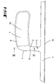
- On the Sheet 15 is by means of rivets, not shown
- Fastening section 4, which is designed as a rib is assembled. Approximately in the middle of the fastening section 4 a spacing section 3 projects approximately at right angles from the rib. The spacing section 3 sits approximately in a straight line in an insertion section 5 continues.
- Fastening section 4, spacing section 3 and insertion section 5 form the same material the bracket 2.
- the insertion section 5 has one truncated pyramid shape. It tapers in the direction of insertion and has a rounded end edge 14.
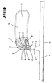
- the handle consists essentially of one circular cylindrical plastic body, the has a solid hard core 10 which of is surrounded by a soft plastic jacket 9. In the area the insertion opening 6, the hard core 10 extends to the Grip surface.
- the insertion opening 6 extends up to the imaginary longitudinal central axis of the handle and has a distance of a few millimeters from the front 7 of the handle 1. This makes a small step 13 formed, behind which the spacing section 3 extends.
- the insertion section 5 has a push-through opening 12.
- a countersunk screw screwed into the front side 7 8 penetrates the push-through opening with its shaft 12 and is with its threaded section 8 '' in a screw hole 11 made of hard plastic existing core 10 of the handle 1 screwed.
- the Countersunk head 8 'of screw 8 is flush with the Screwed surface of the end face 7.
- the assembly of the Grip by a pressing movement towards the surface normal of sheet 3 can be done. Furthermore, as considered advantageous that on a roughly parallel to Rib 4 extending tang can be completely dispensed with can.
- the manufacture of the handle by injection molding has proven to be beneficial. By design a tool in which the core, which in the Insert opening 6 is the same shape as the insertion section 5, which generates when the injection molded plastic part occurring shrinkage an adhesive force with the pressure in the insertion opening 6 pressed-in insertion section 5.
- the assembly can be done with a pneumatic pressure cylinder.
- the sheet 15 is preferably made of steel.
- the bracket consists preferably of aluminum.
- the resistance of the trowel according to the invention is not weakened by the fact that the bracket is manufactured as an aluminum casting.
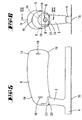
- the embodiment shown in Figures 5 to 7 differs from that previously described Embodiment in that the spacing section 3 below the end face 7 a material thickening 20, so that the spacing section 3rd merges into the end face 7.
- a joint 21 Between the Material thickening 20 and the handle 1 is a joint 21 provided that the width is about 1 mm or less has. This is a tight pressing on the Handle on the insertion section 5 possible. Under this radial pressure load on the handle 1 can Locking pin 8 can be pushed in or screwed in.
- the joint 21 occurs when, according to decreasing radial pressure of the insertion section 5 slightly springs out of the radial opening 6.
- the handle 1 consists of a hard plastic core 10, which in turn consists of two half-open core parts 16, 17 composed.
- the core parts 16, 17 are inserted one into the other, that they have a closed cavity 22 form.
- the edge sections 16 ', 17' form catches 23, so that the two core parts 16, 17 are pre-assembled can become and not fall apart.
- the two core parts 16, 17 can also be glued together become.
- the core parts 16 on the outer wall of the casing have 17 webs 19.
- the height of the webs 19 corresponds to the thickness the soft plastic jacket wall 9.
- the webs 19 serve as centering protrusions when the composite hard plastic core is inserted into an injection mold to to be encapsulated with soft plastic.
- This soft plastic encapsulation also keeps the two half-open Core parts 16, 17 in connection with each other.
- the joint 18 between the core parts 16, 17 is made of soft plastic covered. The one after the overmolding Shrinkage of the soft plastic keeps them both Core parts 16, 17 firmly together.
Landscapes
- Engineering & Computer Science (AREA)
- Architecture (AREA)
- Civil Engineering (AREA)
- Structural Engineering (AREA)
- Mechanical Engineering (AREA)
- Coating Apparatus (AREA)
- Confectionery (AREA)
- Injection Moulding Of Plastics Or The Like (AREA)
- Details Of Rigid Or Semi-Rigid Containers (AREA)
Claims (10)
- Truelle avec une poignée, présentant une lame (15) à laquelle est appliquée une attache (2) pour la poignée (1), l'attaque (2) étant fixée au moyen d'une partie de fixation (4) sur la lame (15), dans laquelle truelle comporte l'attache présentant une partie d'écartement (3) et s'insère au moyen d'une partie d'insertion (5) dans une ouverture de la poignée (1), cette l'ouverture étant une ouverture radiale (6), caractérisée en ce que la partie d'insertion (5) est sécurisée contre son extraction au moyen d'une broche de sécurité (8) introduite dans la poignée, la partie d'insertion (5) étant effilée dans la direction d'insertion.
- Truelle selon la revendication 1, caractérisée en ce que la partie d'insertion (5) est disposée à l'intérieur de l'évidement radial (6) en conjugaison de forme.
- Truelle selon la revendication 1, caractérisée en ce que la poignée est une pièce en matière synthétique moulée par injection.
- Truelle selon une ou plusieurs des revendications précédentes, caractérisée en ce que la partie d'insertion (5) est un prolongement sensiblement linéaire de la partie d'écartement (3).
- Truelle selon une ou plusieurs des revendications précédentes, caractérisée en ce que la partie d'insertion (5) présente une forme de pyramide tronquée et, en particulier présente une zone arrondie (14) du côté de son extrémité.
- Truelle selon une ou plusieurs des revendications précédentes, caractérisée en ce que la truelle est une truelle de lissage dans laquelle la partie de fixation (4) est fixée sur la lame au moyen de rivets ou similaires et la partie d'écartement (3) fait saillie aux alentours du milieu de la partie de fixation (4).
- Poignée pour une truelle selon une ou plusieurs des revendications précédentes, caractérisée par une ouverture (6) radiale disposée dans la zone de sa face frontale (7) pour l'introduction d'une partie d'insertion (5) d'une partie de fixation (4), l'ouverture radiale étant disposée dans un noyau (10) en une matière synthétique dure, qui est entourée au moins partiellement par de matière synthétique molle, et qui présente une ouverture axiale pour l'introduction ou le vissage d'une broche de sécurité (8) qui croise l'ouverture radiale (6).
- Truelle ou poignée selon une ou plusieurs des revendications précédentes, caractérisée en ce que la poignée (1) présente un noyau en matière synthétique dure et une enveloppe (9) en matière synthétique molle, l'ouverture d'insertion (6) étant associée au noyau (10).
- Truelle ou poignée selon la revendication 10, caractérisée en ce que les deux parties de noyau (16, 17) se verrouille par encliquetage avec des moyens en formant une zone de recouvrement (16', 17') d'encliquetage (23).
- Truelle ou poignée selon la revendication 11, caractérisée par des nervures (19) faisant saillie vers l'extérieur à partir du noyau (10) en matière synthétique dure, et dont la hauteur correspond à l'épaisseur de l'enveloppe en matière synthétique molle.
Applications Claiming Priority (2)
| Application Number | Priority Date | Filing Date | Title |
|---|---|---|---|
| DE29800879U DE29800879U1 (de) | 1998-01-20 | 1998-01-20 | Kelle mit Griff |
| DE29800879U | 1998-01-20 |
Publications (3)
| Publication Number | Publication Date |
|---|---|
| EP0930133A2 EP0930133A2 (fr) | 1999-07-21 |
| EP0930133A3 EP0930133A3 (fr) | 2001-05-09 |
| EP0930133B1 true EP0930133B1 (fr) | 2004-08-04 |
Family
ID=8051479
Family Applications (1)
| Application Number | Title | Priority Date | Filing Date |
|---|---|---|---|
| EP98123859A Expired - Lifetime EP0930133B1 (fr) | 1998-01-20 | 1998-12-16 | Truelle avec poignée |
Country Status (4)
| Country | Link |
|---|---|
| US (1) | US6223384B1 (fr) |
| EP (1) | EP0930133B1 (fr) |
| AT (1) | ATE272467T1 (fr) |
| DE (2) | DE29800879U1 (fr) |
Families Citing this family (15)
| Publication number | Priority date | Publication date | Assignee | Title |
|---|---|---|---|---|
| US6604256B1 (en) * | 2000-08-01 | 2003-08-12 | Walter W. Pytlewski | Grout float assembly |
| US6513199B1 (en) * | 2001-10-26 | 2003-02-04 | Chun-Yong Cheng | Handle of a trowel |
| US6640378B2 (en) * | 2001-10-29 | 2003-11-04 | Chiung Yueh Hsu | Trowel having an integral and comfortable handle |
| US6905290B1 (en) | 2003-09-22 | 2005-06-14 | Andrew Casciato, Jr. | Hand rasp with groove blade and adjustable guide for scoring construction material |
| US8151404B1 (en) | 2005-01-26 | 2012-04-10 | Beno J. Gundlach Company | Modular trowel handle |
| US7370384B2 (en) * | 2005-01-27 | 2008-05-13 | Custom Building Products, Inc. | Combination wedge and notch trowel with reversible grip handle |
| US8434188B1 (en) | 2007-09-19 | 2013-05-07 | Exceptional Ip Holdings, Llc | Apparatus and methods for ergonomic building tools |
| US8621817B1 (en) | 2010-12-03 | 2014-01-07 | Kenneth Robert Kreizinger | Vertical vibrating screed |
| US10583625B2 (en) | 2015-06-30 | 2020-03-10 | Braun Gmbh | Plurality of mass-produced multi-component plastic housings |
| US10226315B2 (en) * | 2015-06-30 | 2019-03-12 | Braun Gmbh | Multi-component plastic housing |
| USD1031396S1 (en) * | 2022-07-19 | 2024-06-18 | Maurerfreund Gmbh | Mason's trowel |
| US11866947B1 (en) | 2022-10-05 | 2024-01-09 | Acufloor, LLC | Hand trowel and hand trowel handle for use with the same |
| USD996169S1 (en) | 2022-10-05 | 2023-08-22 | Acufloor, LLC | Trowel handle |
| USD998443S1 (en) | 2022-10-05 | 2023-09-12 | Acufloor, LLC | Trowel handle |
| USD997682S1 (en) | 2022-10-05 | 2023-09-05 | Acufloor, LLC | Trowel handle |
Family Cites Families (19)
| Publication number | Priority date | Publication date | Assignee | Title |
|---|---|---|---|---|
| US696066A (en) * | 1901-04-02 | 1902-03-25 | Philip S Miller | Plastering-trowel. |
| US1168643A (en) * | 1914-08-04 | 1916-01-18 | Charles E Johnson | Trowel. |
| US2076836A (en) * | 1936-11-30 | 1937-04-13 | Louis I Goldblatt | Implement handle |
| US2578163A (en) * | 1949-07-09 | 1951-12-11 | Wha Lite Products | Plasterer's darby |
| US2896441A (en) * | 1956-04-26 | 1959-07-28 | Jo W Tucker | Adjustable joint trowel |
| US3045271A (en) * | 1960-09-21 | 1962-07-24 | Julius A Cinotti | Universal concrete edger |
| DE1875730U (de) * | 1963-05-16 | 1963-07-18 | P Hermann Jung Fa | Kelle fuer bauarbeiten, insbesondere glaettekelle. |
| DE2001072A1 (de) * | 1970-01-12 | 1971-07-22 | Guenter Leveringhaus | Werkzeug zum Glaetten von Bauflaechen |
| DE8433183U1 (de) * | 1984-11-13 | 1985-02-14 | Madel, Paul, 5650 Solingen | Spachtel |
| DE3540565A1 (de) * | 1985-11-15 | 1987-06-19 | Torsten Schmechel | Kraftuebertragungsgriff |
| US4817231A (en) * | 1986-04-16 | 1989-04-04 | Amco Tool And Stamping Co., Inc. | Durable trowel construction |
| US4884312A (en) * | 1987-01-20 | 1989-12-05 | Clark Ronald M | Hand trowel |
| US5097909A (en) * | 1991-05-17 | 1992-03-24 | Jauhal Kuldip S | Garden trowel tool kit |
| US5327612A (en) | 1993-03-02 | 1994-07-12 | Marshalltown Trowel Company | Plastic molded trowel handle having fingerguard and palm grip |
| US5522111A (en) * | 1993-03-02 | 1996-06-04 | Marshalltown Trowel Company | Finishing trowel handle |
| US5491896A (en) * | 1993-12-17 | 1996-02-20 | Ryobi Motor Products | Attachment and accessory scraper blades for detail sander |
| US5615445A (en) * | 1994-12-27 | 1997-04-01 | Marshalltown Trowel Company | Taping knife handle |
| US5632569A (en) * | 1995-06-19 | 1997-05-27 | Szmansky; Les | Cement finishing hand tool |
| US5956799A (en) * | 1997-09-10 | 1999-09-28 | Panaccione; Mark Thomas | Putty knife and scraper handle |
-
1998
- 1998-01-20 DE DE29800879U patent/DE29800879U1/de not_active Expired - Lifetime
- 1998-12-16 AT AT98123859T patent/ATE272467T1/de not_active IP Right Cessation
- 1998-12-16 DE DE59811753T patent/DE59811753D1/de not_active Expired - Lifetime
- 1998-12-16 EP EP98123859A patent/EP0930133B1/fr not_active Expired - Lifetime
-
1999
- 1999-01-14 US US09/231,858 patent/US6223384B1/en not_active Expired - Lifetime
Also Published As
| Publication number | Publication date |
|---|---|
| EP0930133A2 (fr) | 1999-07-21 |
| DE29800879U1 (de) | 1999-01-21 |
| US6223384B1 (en) | 2001-05-01 |
| EP0930133A3 (fr) | 2001-05-09 |
| DE59811753D1 (de) | 2004-09-09 |
| ATE272467T1 (de) | 2004-08-15 |
Similar Documents
| Publication | Publication Date | Title |
|---|---|---|
| EP0930133B1 (fr) | Truelle avec poignée | |
| EP1627608B1 (fr) | Elément de serrage et élément de joint | |
| DE69821176T2 (de) | Werkzeug mit Griff aus zwei Werkstoffen | |
| EP1055076A1 (fr) | Cuvette rotule destinee a un joint a rotule et joint a rotule dotee d'une telle cuvette rotule | |
| WO2004075690A1 (fr) | Poignee de porte | |
| EP0292742A1 (fr) | Vis d'écartement | |
| DE3105217C2 (de) | Befestigungsvorrichtung an lösbar miteinander verbindbaren Beschlag- oder Ausstattungsteilen und Verfahren zur Herstellung derselben | |
| DE69828298T2 (de) | Vorrichtungen zum herstellen einer verbindung | |
| DE2420264B2 (de) | Verfahren zur Herstellung eines Kunststoffscharniers aus Spritzguß und Kunststoffscharnier | |
| EP3927483A1 (fr) | Corps monobloc de dispositif d'alimentation, destiné à être utilisé lors de la coulée de métaux | |
| DE8434255U1 (de) | Griff für Stielwerkzeuge, insbesondere für Feilen, Raspeln od. dgl. | |
| DE29619634U1 (de) | Doppel-Profilschließzylinder | |
| DE3036498A1 (de) | Kunststoffprofilscharnier fuer schaltuschranktueren | |
| DE2947299C2 (fr) | ||
| DE29710853U1 (de) | Scharnier für Blechschranktüren | |
| DE1500909A1 (de) | Mit einem oder mehreren Schraubengewindeloechern versehener Gegenstand,insbesondere aus Kunststoff | |
| EP0058391B1 (fr) | Dispositif de fixation sur des pièces de garnissage ou d'installation pouvant être reliées l'une à l'autre de manière amovible et procédé pour la fabrication d'un tel dispositif | |
| EP0974716A2 (fr) | Poignée de porte, poignée de fenêtre, ou élément sanitaire | |
| DE4440220A1 (de) | Verbindungsvorrichtung zur Verbindung der Sprossen einer Leiter mit den Holmen einer Leiter | |
| EP1241363B1 (fr) | Magasin pour le magasinage d'éléments de fixation | |
| DE8104809U1 (de) | Aus Kunststoff bestehendes einstückiges Lagergehäuse | |
| EP0006139A1 (fr) | Vis à empreinte cruciforme avec couvercle et procédé de fabrication de cette vis | |
| DE202015104633U1 (de) | Schraubverbindungselement | |
| DE102022123451A1 (de) | Luftleitvorrichtung einer Kraftfahrzeugkarosserie eines Kraftfahrzeugs | |
| EP4426602A1 (fr) | Sonnette pour guidon de vélo |
Legal Events
| Date | Code | Title | Description |
|---|---|---|---|
| PUAI | Public reference made under article 153(3) epc to a published international application that has entered the european phase |
Free format text: ORIGINAL CODE: 0009012 |
|
| AK | Designated contracting states |
Kind code of ref document: A2 Designated state(s): AT DE ES FR GB IT NL |
|
| AX | Request for extension of the european patent |
Free format text: AL;LT;LV;MK;RO;SI |
|
| PUAL | Search report despatched |
Free format text: ORIGINAL CODE: 0009013 |
|
| AK | Designated contracting states |
Kind code of ref document: A3 Designated state(s): AT BE CH CY DE DK ES FI FR GB GR IE IT LI LU MC NL PT SE |
|
| AX | Request for extension of the european patent |
Free format text: AL;LT;LV;MK;RO;SI |
|
| RIC1 | Information provided on ipc code assigned before grant |
Free format text: 7B 25G 3/26 A, 7B 25G 1/10 B, 7E 04F 21/06 B, 7E 04F 21/16 B, 7B 25G 3/10 B |
|
| 17P | Request for examination filed |
Effective date: 20010921 |
|
| AKX | Designation fees paid |
Free format text: AT BE CH CY DE DK ES LI |
|
| RBV | Designated contracting states (corrected) |
Designated state(s): AT DE ES FR GB IT NL |
|
| 17Q | First examination report despatched |
Effective date: 20030605 |
|
| GRAP | Despatch of communication of intention to grant a patent |
Free format text: ORIGINAL CODE: EPIDOSNIGR1 |
|
| GRAS | Grant fee paid |
Free format text: ORIGINAL CODE: EPIDOSNIGR3 |
|
| GRAA | (expected) grant |
Free format text: ORIGINAL CODE: 0009210 |
|
| AK | Designated contracting states |
Kind code of ref document: B1 Designated state(s): AT DE ES FR GB IT NL |
|
| PG25 | Lapsed in a contracting state [announced via postgrant information from national office to epo] |
Ref country code: NL Free format text: LAPSE BECAUSE OF FAILURE TO SUBMIT A TRANSLATION OF THE DESCRIPTION OR TO PAY THE FEE WITHIN THE PRESCRIBED TIME-LIMIT Effective date: 20040804 Ref country code: IT Free format text: LAPSE BECAUSE OF FAILURE TO SUBMIT A TRANSLATION OF THE DESCRIPTION OR TO PAY THE FEE WITHIN THE PRESCRIBED TIME-LIMIT;WARNING: LAPSES OF ITALIAN PATENTS WITH EFFECTIVE DATE BEFORE 2007 MAY HAVE OCCURRED AT ANY TIME BEFORE 2007. THE CORRECT EFFECTIVE DATE MAY BE DIFFERENT FROM THE ONE RECORDED. Effective date: 20040804 Ref country code: GB Free format text: LAPSE BECAUSE OF FAILURE TO SUBMIT A TRANSLATION OF THE DESCRIPTION OR TO PAY THE FEE WITHIN THE PRESCRIBED TIME-LIMIT Effective date: 20040804 Ref country code: FR Free format text: LAPSE BECAUSE OF FAILURE TO SUBMIT A TRANSLATION OF THE DESCRIPTION OR TO PAY THE FEE WITHIN THE PRESCRIBED TIME-LIMIT Effective date: 20040804 |
|
| REG | Reference to a national code |
Ref country code: GB Ref legal event code: FG4D Free format text: NOT ENGLISH |
|
| REF | Corresponds to: |
Ref document number: 59811753 Country of ref document: DE Date of ref document: 20040909 Kind code of ref document: P |
|
| PG25 | Lapsed in a contracting state [announced via postgrant information from national office to epo] |
Ref country code: ES Free format text: LAPSE BECAUSE OF FAILURE TO SUBMIT A TRANSLATION OF THE DESCRIPTION OR TO PAY THE FEE WITHIN THE PRESCRIBED TIME-LIMIT Effective date: 20041115 |
|
| PG25 | Lapsed in a contracting state [announced via postgrant information from national office to epo] |
Ref country code: AT Free format text: LAPSE BECAUSE OF NON-PAYMENT OF DUE FEES Effective date: 20041216 |
|
| NLV1 | Nl: lapsed or annulled due to failure to fulfill the requirements of art. 29p and 29m of the patents act | ||
| GBV | Gb: ep patent (uk) treated as always having been void in accordance with gb section 77(7)/1977 [no translation filed] |
Effective date: 20040804 |
|
| PLBE | No opposition filed within time limit |
Free format text: ORIGINAL CODE: 0009261 |
|
| STAA | Information on the status of an ep patent application or granted ep patent |
Free format text: STATUS: NO OPPOSITION FILED WITHIN TIME LIMIT |
|
| 26N | No opposition filed |
Effective date: 20050506 |
|
| EN | Fr: translation not filed | ||
| REG | Reference to a national code |
Ref country code: DE Ref legal event code: R082 Ref document number: 59811753 Country of ref document: DE Representative=s name: RIEDER & PARTNER MBB PATENTANWAELTE - RECHTSAN, DE Effective date: 20110628 Ref country code: DE Ref legal event code: R082 Ref document number: 59811753 Country of ref document: DE Representative=s name: RIEDER & PARTNER PATENTANWAELTE - RECHTSANWALT, DE Effective date: 20110628 Ref country code: DE Ref legal event code: R081 Ref document number: 59811753 Country of ref document: DE Owner name: MAURERFREUND GMBH, DE Free format text: FORMER OWNER: MAURERFREUND GMBH, 42349 WUPPERTAL, DE Effective date: 20110628 |
|
| PGFP | Annual fee paid to national office [announced via postgrant information from national office to epo] |
Ref country code: DE Payment date: 20171213 Year of fee payment: 20 |
|
| REG | Reference to a national code |
Ref country code: DE Ref legal event code: R071 Ref document number: 59811753 Country of ref document: DE |