EP0930133B1 - Trowel with handle - Google Patents
Trowel with handle Download PDFInfo
- Publication number
- EP0930133B1 EP0930133B1 EP98123859A EP98123859A EP0930133B1 EP 0930133 B1 EP0930133 B1 EP 0930133B1 EP 98123859 A EP98123859 A EP 98123859A EP 98123859 A EP98123859 A EP 98123859A EP 0930133 B1 EP0930133 B1 EP 0930133B1
- Authority
- EP
- European Patent Office
- Prior art keywords
- handle
- section
- trowel
- opening
- insertion section
- Prior art date
- Legal status (The legal status is an assumption and is not a legal conclusion. Google has not performed a legal analysis and makes no representation as to the accuracy of the status listed.)
- Expired - Lifetime
Links
- 238000003780 insertion Methods 0.000 claims abstract description 44
- 230000037431 insertion Effects 0.000 claims abstract description 44
- 229920003023 plastic Polymers 0.000 claims description 25
- 239000004033 plastic Substances 0.000 claims description 25
- 238000009499 grossing Methods 0.000 claims description 5
- 238000002347 injection Methods 0.000 claims description 5
- 239000007924 injection Substances 0.000 claims description 5
- 229920002457 flexible plastic Polymers 0.000 claims 2
- 230000015572 biosynthetic process Effects 0.000 claims 1
- 230000000295 complement effect Effects 0.000 claims 1
- 239000002991 molded plastic Substances 0.000 abstract description 2
- 125000006850 spacer group Chemical group 0.000 abstract 1
- 239000000463 material Substances 0.000 description 5
- 238000004519 manufacturing process Methods 0.000 description 4
- XAGFODPZIPBFFR-UHFFFAOYSA-N aluminium Chemical compound [Al] XAGFODPZIPBFFR-UHFFFAOYSA-N 0.000 description 2
- 229910052782 aluminium Inorganic materials 0.000 description 2
- 238000001746 injection moulding Methods 0.000 description 2
- 230000008719 thickening Effects 0.000 description 2
- 229910000831 Steel Inorganic materials 0.000 description 1
- 239000000853 adhesive Substances 0.000 description 1
- 230000001070 adhesive effect Effects 0.000 description 1
- 230000009286 beneficial effect Effects 0.000 description 1
- 238000005266 casting Methods 0.000 description 1
- 239000002131 composite material Substances 0.000 description 1
- 230000003247 decreasing effect Effects 0.000 description 1
- 238000011161 development Methods 0.000 description 1
- 230000018109 developmental process Effects 0.000 description 1
- 230000000694 effects Effects 0.000 description 1
- 238000005538 encapsulation Methods 0.000 description 1
- 210000001061 forehead Anatomy 0.000 description 1
- 210000003128 head Anatomy 0.000 description 1
- 239000006223 plastic coating Substances 0.000 description 1
- 239000007787 solid Substances 0.000 description 1
- 239000010959 steel Substances 0.000 description 1
- 210000003813 thumb Anatomy 0.000 description 1
Images


Classifications
-
- B—PERFORMING OPERATIONS; TRANSPORTING
- B25—HAND TOOLS; PORTABLE POWER-DRIVEN TOOLS; MANIPULATORS
- B25G—HANDLES FOR HAND IMPLEMENTS
- B25G3/00—Attaching handles to the implements
- B25G3/02—Socket, tang, or like fixings
- B25G3/12—Locking and securing devices
- B25G3/26—Locking and securing devices comprising nails, screws, bolts, or pins traversing or entering the socket
-
- E—FIXED CONSTRUCTIONS
- E04—BUILDING
- E04F—FINISHING WORK ON BUILDINGS, e.g. STAIRS, FLOORS
- E04F21/00—Implements for finishing work on buildings
- E04F21/02—Implements for finishing work on buildings for applying plasticised masses to surfaces, e.g. plastering walls
- E04F21/16—Implements for after-treatment of plaster or the like before it has hardened or dried, e.g. smoothing-tools, profile trowels
- E04F21/161—Trowels
Definitions
- the invention relates to a trowel with a handle a sheet and attached holder for the Handle according to the preamble of claim 1.
- Such a trowel is known in the prior art.
- the US patent is only given as an example 5,446,941 or 5,522,111.
- the mounting section sets progress in a spacing section.
- smoothing trowel is the Fastening section than essentially over the entire length of the blade extending rib designed.
- the spacing section protrudes approximately at right angles from the mounting section.
- the handle is attached, which is about extends parallel to the rib.
- the handle is by means of an insertion section connected to the bracket.
- the insertion section is in the prior art as rod protruding in the longitudinal direction trained which with an end nut with the Handle is attached.
- the insertion section protrudes approximately perpendicular to the spacing section.
- a smoothing trowel is known from GM 18 75 730, where a hinge penetrates a handle.
- a Similar smoothing trowel is known from DE 35 40 565 A1.
- a hinge also penetrates the handle there. in the A push-on neck sits with the forehead area of the handle laterally projecting wings for thumb support.
- the invention has for its object a generic Trowel while maintaining the measures of the prior art, the advantages of use are easier to assemble or to ensure production.
- the handle without the conventional, in the longitudinal direction of the handle Angel is connected to the trowel.
- the insertion section is in a radial opening of the handle.
- the handle is now no longer by sliding it open in its longitudinal direction on a hinge connected to the bracket, but by plugging in the radial direction onto the insertion section of the holder.
- the insertion section is by a locking pin axially inserted into the handle secured against pulling out. It tapers in its direction of insertion. If the insertion section conforms to the shape of the radial recess According to the taper, a wedge effect occurs, which means that there is no play Holder of the handle on the insertion section comes towards.
- the Handle is advantageously molded from a plastic.
- the core of the injection mold which lies in the radial recess, the shape of the Own insertion section. Due to the production-related low Shrinkage of the plastic material is then a tight fit of the insertion section guaranteed in the insertion opening (radial recess).
- the insertion section is essentially one straight the spacing section. This variant is This is particularly advantageous for trowels.
- the insertion section can have a rounded end. This is advantageous in terms of injection molding. But it also brings Advantages in the production of the over the conventional long fishing stub-like insertion section, which extends into the handle beyond the center of the handle extends.
- the insertion section can have a pyramid shape have.
- the locking pin by means of which the Insertion section in the form-fitting radial recess is held, can be designed as a countersunk screw be screwed into the handle on the front is and penetrates an opening of the insertion portion.
- the thread of the countersunk screw cuts thereby into the massive handle volume.
- a preferred one Design is made of a hard plastic existing handle body with a soft plastic jacket overdrawn. It is advantageous if the front side of the handle into which the countersunk screw is screwed is made of hard plastic material.
- the invention also includes a handle for a Trowel or the like.
- the handle has in the area of his Front a radial opening for inserting a Insert section of a fastening section or like.
- the handle preferably consists of a Hard plastic core, which is preferably a hollow body formed. This hollow body can consist of two semi-hollow ones Core parts be assembled. The two half-height Core parts form a when plugged together Parting line. This parting line is the soft plastic jacket covered. Put the two core parts together the edges of the core parts are narrower designed so that an overlap zone is formed. The two core parts lock in this overlap zone together. On the outside of the core part webs are arranged, the height of the thickness of the soft plastic coating equivalent.
- the put together Hard plastic core can with a gap spacing placed in an injection mold and centered, whereby the web is supported on the mold nest. In these The soft plastic is then injected, so that the end faces of the webs with the soft plastic jacket exposed flush to the outside.
- the invention is explained on the basis of a Trowel. But it is also possible to use the invention Handle on a trowel or another designed masonry tool to implement.
- On the Sheet 15 is by means of rivets, not shown
- Fastening section 4, which is designed as a rib is assembled. Approximately in the middle of the fastening section 4 a spacing section 3 projects approximately at right angles from the rib. The spacing section 3 sits approximately in a straight line in an insertion section 5 continues.
- Fastening section 4, spacing section 3 and insertion section 5 form the same material the bracket 2.
- the insertion section 5 has one truncated pyramid shape. It tapers in the direction of insertion and has a rounded end edge 14.
- the handle consists essentially of one circular cylindrical plastic body, the has a solid hard core 10 which of is surrounded by a soft plastic jacket 9. In the area the insertion opening 6, the hard core 10 extends to the Grip surface.
- the insertion opening 6 extends up to the imaginary longitudinal central axis of the handle and has a distance of a few millimeters from the front 7 of the handle 1. This makes a small step 13 formed, behind which the spacing section 3 extends.
- the insertion section 5 has a push-through opening 12.
- a countersunk screw screwed into the front side 7 8 penetrates the push-through opening with its shaft 12 and is with its threaded section 8 '' in a screw hole 11 made of hard plastic existing core 10 of the handle 1 screwed.
- the Countersunk head 8 'of screw 8 is flush with the Screwed surface of the end face 7.
- the assembly of the Grip by a pressing movement towards the surface normal of sheet 3 can be done. Furthermore, as considered advantageous that on a roughly parallel to Rib 4 extending tang can be completely dispensed with can.
- the manufacture of the handle by injection molding has proven to be beneficial. By design a tool in which the core, which in the Insert opening 6 is the same shape as the insertion section 5, which generates when the injection molded plastic part occurring shrinkage an adhesive force with the pressure in the insertion opening 6 pressed-in insertion section 5.
- the assembly can be done with a pneumatic pressure cylinder.
- the sheet 15 is preferably made of steel.
- the bracket consists preferably of aluminum.
- the resistance of the trowel according to the invention is not weakened by the fact that the bracket is manufactured as an aluminum casting.
- the embodiment shown in Figures 5 to 7 differs from that previously described Embodiment in that the spacing section 3 below the end face 7 a material thickening 20, so that the spacing section 3rd merges into the end face 7.
- a joint 21 Between the Material thickening 20 and the handle 1 is a joint 21 provided that the width is about 1 mm or less has. This is a tight pressing on the Handle on the insertion section 5 possible. Under this radial pressure load on the handle 1 can Locking pin 8 can be pushed in or screwed in.
- the joint 21 occurs when, according to decreasing radial pressure of the insertion section 5 slightly springs out of the radial opening 6.
- the handle 1 consists of a hard plastic core 10, which in turn consists of two half-open core parts 16, 17 composed.
- the core parts 16, 17 are inserted one into the other, that they have a closed cavity 22 form.
- the edge sections 16 ', 17' form catches 23, so that the two core parts 16, 17 are pre-assembled can become and not fall apart.
- the two core parts 16, 17 can also be glued together become.
- the core parts 16 on the outer wall of the casing have 17 webs 19.
- the height of the webs 19 corresponds to the thickness the soft plastic jacket wall 9.
- the webs 19 serve as centering protrusions when the composite hard plastic core is inserted into an injection mold to to be encapsulated with soft plastic.
- This soft plastic encapsulation also keeps the two half-open Core parts 16, 17 in connection with each other.
- the joint 18 between the core parts 16, 17 is made of soft plastic covered. The one after the overmolding Shrinkage of the soft plastic keeps them both Core parts 16, 17 firmly together.
Abstract
Description
Die Erfindung betrifft eine Kelle mit Griff, aufweisend
ein Blatt und daran angebrachter Halterung für den
Griff gemäß Gattungsbegriff des Anspruchs 1.The invention relates to a trowel with a handle
a sheet and attached holder for the
Handle according to the preamble of
Eine derartige Kelle ist im Stand der Technik bekannt. Lediglich beispielhaft wird auf die US-Patentschrift 5,446,941 oder 5,522,111 hingewiesen. Dort ist die Halterung für den Griff mit einem Befestigungsabschnitt am Blatt befestigt. Der Befestigungsabschnitt setzt sich fort in einem Beabstandungsabschnitt. Bei der in der US-PS 5,522,111 dargestellten Glättekelle ist der Befestigungsabschnitt als sich im wesentlichen über die gesamte Länge des Blattes erstreckende Rippe ausgestaltet. Der Beabstandungsabschnitt ragt etwa rechtwinklig vom Befestigungsabschnitt ab. Am Ende des Beabstandungsabschnittes ist der Griff befestigt, welcher sich etwa parallel zur Rippe erstreckt. Der Griff ist mittels eines Einsteckabschnittes mit der Halterung verbunden. Der Einsteckabschnitt ist beim Stand der Technik als den Griff in seiner Längsrichtung durchragende Angel ausgebildet, welche über eine endseitige Mutter mit dem Griff befestigt ist. Der Einsteckabschnitt ragt etwa rechtwinklig vom Beabstandungsabschnitt ab.Such a trowel is known in the prior art. The US patent is only given as an example 5,446,941 or 5,522,111. There is the Holder for the handle with a fastening section attached to the leaf. The mounting section sets progress in a spacing section. At the in US Pat. No. 5,522,111 smoothing trowel is the Fastening section than essentially over the entire length of the blade extending rib designed. The spacing section protrudes approximately at right angles from the mounting section. At the end of the spacing section the handle is attached, which is about extends parallel to the rib. The handle is by means of an insertion section connected to the bracket. The insertion section is in the prior art as rod protruding in the longitudinal direction trained which with an end nut with the Handle is attached. The insertion section protrudes approximately perpendicular to the spacing section.
Ferner ist aus dem GM 18 75 730 eine Glättekelle bekannt, bei der eine Angel einen Griff durchsetzt. Eine ähnliche Glättekelle ist aus der DE 35 40 565 A1 bekannt. Auch dort durchsetzt eine Angel den Griff. Im Stirnbereich des Griffes sitzt ein Aufsteckhals mit seitlich abragenden Flügeln zur Daumenabstützung.Furthermore, a smoothing trowel is known from GM 18 75 730, where a hinge penetrates a handle. A Similar smoothing trowel is known from DE 35 40 565 A1. A hinge also penetrates the handle there. in the A push-on neck sits with the forehead area of the handle laterally projecting wings for thumb support.
Der Erfindung liegt die Aufgabe zugrunde, eine gattungsgemäße Kelle unter Beibehaltung des mit den Maßnahmen des Standes der Technik erzielten Gebrauchsvorteilen eine einfachere Montage bzw. Herstellung zu gewährleisten.The invention has for its object a generic Trowel while maintaining the measures of the prior art, the advantages of use are easier to assemble or to ensure production.
Gelöst wird die Aufgabe durch die in Anspruch 1 angegebene Erfindung. Die
Unteransprüche stellen vorteilhafte Weiterbildungen dar.The object is achieved by the invention specified in
Zufolge der erfindungsgemäßen Ausgestaltung ist eine Kelle gegeben, bei welcher der Griff ohne die herkömmliche, in Längsrichtung des Griffes verlaufende Angel mit der Kelle verbunden ist. Der Einsteckabschnitt steckt in einer Radialöffnung des Griffes. Der Griff wird jetzt nicht mehr durch ein Aufschieben in seiner Längsrichtung auf eine Angel mit der Halterung verbunden, sondern durch ein Aufstecken in Radialrichtung auf den Einsteckabschnitt der Halterung. Der Einsteckabschnitt ist durch einen axial in den Griff eingesteckten Sicherungsstift gegen Herausziehen gesichert. Es verjüngt sich in seiner Einsteckrichtung. Wenn der Einsteckabschnitt formangepaßt in der Radialaussparung liegen soll, tritt zufolge der Verjüngung eine Keilwirkung ein, was einer spielfreien Halterung des Griffs auf dem Einsteckabschnitt entgegenkommt. Der Griff ist vorteilhafterweise aus einem Kunststoff gespritzt. Der Kern der Spritzgussform, welcher in der Radialaussparung einliegt, kann dabei die Form des Einsteckabschnittes besitzen. Zufolge der produktionsbedingten geringen Schwindung des Kunststoffmaterials ist dann ein straffer Sitz des Einsteckabschnittes in der Einstecköffnung (Radialaussparung) gewährleistet. In einer weiteren vorteilhaften Ausgestaltung ist der Einsteckabschnitt eine im wesentlichen geradlinige gerung des Beabstandungsabschnittes. Diese Variante ist insbesondere bei Glättekellen von Vorteil. Der Einsteckabschnitt kann eine endseitige Abrundung besitzen. Dies ist spritzgußtechnisch vorteilhaft. Es bringt aber auch Vorteile bei der Fertigung des gegenüber den herkömmlichen langen Angeln stummelartigen Einsteckabschnitt, der sich bis über das Zentrum des Griffes in den Griff erstreckt. Der Einsteckabschnitt kann eine Pyramidenform besitzen. Der Sicherungsstift, mittels welchem der Einsteckabschnitt in der formangepaßten Radialaussparung festgehalten ist, kann als Senkkopfschraube ausgebildet sein, die stirnseitig in den Griff eingedreht ist und eine Öffnung des Einsteckabschnittes durchdringt. Das Gewinde der Senkkopfschraube schneidet sich dabei in das massive Griff-Volumen ein. In einer bevorzugten Ausgestaltung ist der aus einem harten Kunststoff bestehende Griffkörper mit einem Weichkunststoffmantel überzogen. Vorteilhaft ist, wenn die Stirnseite des Griffes, in welche die Senkkopfschraube eingeschraubt ist, aus hartem Kunststoffmaterial besteht.As a result of the configuration according to the invention, there is a trowel in which the handle without the conventional, in the longitudinal direction of the handle Angel is connected to the trowel. The insertion section is in a radial opening of the handle. The handle is now no longer by sliding it open in its longitudinal direction on a hinge connected to the bracket, but by plugging in the radial direction onto the insertion section of the holder. The insertion section is by a locking pin axially inserted into the handle secured against pulling out. It tapers in its direction of insertion. If the insertion section conforms to the shape of the radial recess According to the taper, a wedge effect occurs, which means that there is no play Holder of the handle on the insertion section comes towards. The Handle is advantageously molded from a plastic. The core of the injection mold, which lies in the radial recess, the shape of the Own insertion section. Due to the production-related low Shrinkage of the plastic material is then a tight fit of the insertion section guaranteed in the insertion opening (radial recess). In a a further advantageous embodiment, the insertion section is essentially one straight the spacing section. This variant is This is particularly advantageous for trowels. The insertion section can have a rounded end. This is advantageous in terms of injection molding. But it also brings Advantages in the production of the over the conventional long fishing stub-like insertion section, which extends into the handle beyond the center of the handle extends. The insertion section can have a pyramid shape have. The locking pin, by means of which the Insertion section in the form-fitting radial recess is held, can be designed as a countersunk screw be screwed into the handle on the front is and penetrates an opening of the insertion portion. The thread of the countersunk screw cuts thereby into the massive handle volume. In a preferred one Design is made of a hard plastic existing handle body with a soft plastic jacket overdrawn. It is advantageous if the front side of the handle into which the countersunk screw is screwed is made of hard plastic material.
Außerdem umfaßt die Erfindung einen Griff für eine Kelle oder dergleichen. Der Griff hat im Bereich seiner Stirnseite eine Radialöffnung zum Einstecken eines Einsteckabschnittes eines Befestigungsabschnittes oder dergleichen. Der Griff besteht vorzugsweise aus einem Hartkunststoffkern, welcher vorzugsweise einen Hohlkörper ausbildet. Dieser Hohlkörper kann aus zwei halbhohlen Kernteilen zusammengesetzt sein. Die beiden halbhohen Kernteile bilden im zusammengesteckten Zustand eine Trennfuge aus. Diese Trennfuge wird vom Weichkunststoffmantel überdeckt. Um die beiden Kernteile zusammenstekken zu können, sind die Ränder der Kernteile schmaler gestaltet, so daß sich eine Überlappungszone ausbildet. In dieser Überlappungszone verrasten die beiden Kernteile miteinander. Auf der Mantelaußenseite des Kernteiles sind Stege angeordnet, deren Höhe der Dicke der Weichkunststoffummantelung entspricht. Der zusammengesteckte Hartkunststoffkern kann so mit einer Spaltabstandslage in eine Spritzgußform eingelegt und zentriert werden, wobei sich die Steg am Formnest abstützen. In diesen Spaltraum wird dann der Weichkunststoff eingespritzt, so daß die Stirnflächen der Stege mit dem Weichkunststoffmantel fluchtend nach außen freiliegen.The invention also includes a handle for a Trowel or the like. The handle has in the area of his Front a radial opening for inserting a Insert section of a fastening section or like. The handle preferably consists of a Hard plastic core, which is preferably a hollow body formed. This hollow body can consist of two semi-hollow ones Core parts be assembled. The two half-height Core parts form a when plugged together Parting line. This parting line is the soft plastic jacket covered. Put the two core parts together the edges of the core parts are narrower designed so that an overlap zone is formed. The two core parts lock in this overlap zone together. On the outside of the core part webs are arranged, the height of the thickness of the soft plastic coating equivalent. The put together Hard plastic core can with a gap spacing placed in an injection mold and centered, whereby the web is supported on the mold nest. In these The soft plastic is then injected, so that the end faces of the webs with the soft plastic jacket exposed flush to the outside.
Nachfolgend werden Ausführungsbeispiele der Erfindung anhand beigefügter Zeichnungen erläutert. Es zeigen:
- Fig. 1
- eine erfindungsgemäße Kelle in Form einer Glättekelle in der Seitenansicht,
- Fig. 2
- eine Frontalansicht der Kelle gemäß Fig. 1,
- Fig. 3
- ein Schnitt gemäß der Linie III-III in Fig. 1,
- Fig. 4
- eine teilweise aufgebrochene Ansicht gemäß Fig. 1 gemäß der Schnittlinie IV-IV in Fig. 2,
- Fig. 5
- ein zweites Ausführungsbeispiel der Erfindung in der Ansicht,
- Fig. 6
- eine Seitenansicht auf das zweite Ausführungsbeispiel und
- Fig. 7
- einen Schnitt gemäß der Linie VII-VII in Fig. 6.
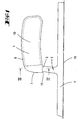
- Fig. 1
- a trowel according to the invention in the form of a smoothing trowel in side view,
- Fig. 2
- 2 shows a frontal view of the trowel according to FIG. 1,
- Fig. 3
- 2 shows a section along the line III-III in FIG. 1,
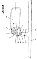
- Fig. 4
- 2 according to the section line IV-IV in FIG. 2,
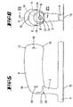
- Fig. 5
- a view of a second embodiment of the invention,
- Fig. 6
- a side view of the second embodiment and
- Fig. 7
- a section along the line VII-VII in Fig. 6.
Die Erläuterung der Erfindung erfolgt anhand einer
Glättekelle. Es ist aber auch möglich, den erfindungsgemäßen
Griff an einer Maurerkelle oder an einem anders
ausgestalteten Maurerwerkzeug zu verwirklichen. Auf dem
Blatt 15 ist mittels nicht dargestellter Nieten der
Befestigungsabschnitt 4, welcher als Rippe ausgebildet
ist, montiert. Etwa in der Mitte des Befestigungsabschnittes
4 ragt ein Beabstandungsabschnitt 3 etwa
rechtwinklig von der Rippe ab. Der Beabstandungsabschnitt
3 setzt sich etwa geradlinig in einen Einsteckabschnitt
5 fort. Befestigungsabschnitt 4, Beabstandungsabschnitt
3 und Einsteckabschnitt 5 bilden materialeinheitlich
die Halterung 2 aus.The invention is explained on the basis of a
Trowel. But it is also possible to use the invention
Handle on a trowel or another
designed masonry tool to implement. On the
Der Einsteckabschnitt 5 besitzt eine im wesentlichen
pyramidenstumpfförmige Form. Er verjüngt sich in Einsteckrichtung
und besitzt eine gerundete Stirnkante 14.
Der Einsteckabschnitt 5, der etwa dieselbe Breite und
Tiefe besitzt wie der Beabstandungsabschnitt 3, steckt
in einer formangepaßten Einstecköffnung 6 des Griffes 1
ein.The
Der Griff besteht im wesentlichen aus einem im wesentlichen
kreiszylinderförmigartigen Kunststoffkörper, der
einen massiven harten Kern 10 besitzt, welcher von
einem Weichkunststoffmantel 9 umgeben ist. Im Bereich
der Einstecköffnung 6 ragt der harte Kern 10 bis an die
Griffoberfläche. Die Einstecköffnung 6 erstreckt sich
bis über die gedachte Längsmittelachse des Griffes und
hat einen wenige Millimeter großen Abstand zur Stirnseite
7 des Griffes 1. Hierdurch ist eine kleine Stufe 13
ausgebildet, hinter welcher der Beabstandungsabschnitt
3 sich erstreckt.The handle consists essentially of one
circular cylindrical plastic body, the
has a solid
Der Einsteckabschnitt 5 besitzt eine Durchstecköffnung
12. Eine in die Stirnseite 7 eingeschraubte Senkkopfschraube
8 durchgreift mit ihrem Schaft die Durchstecköffnung
12 und ist mit ihrem Gewindeabschnitt 8'' in
eine Festschrauböffnung 11 des aus harten Kunststoff
bestehenden Kernes 10 des Griffes 1 eingeschraubt. Der
Senkkopf 8' der Schraube 8 ist dabei bündig in die
Oberfläche der Stirnseite 7 eingeschraubt.The
Es wird als vorteilhaft angesehen, daß die Montage des
Griffes durch eine Preßbewegung in Richtung zur Flächennormale
des Blattes 3 erfolgen kann. Ferner wird als
vorteilhaft angesehen, daß auf eine etwa parallel zur
Rippe 4 verlaufende Angel vollständig verzichtet werden
kann. Die Herstellung des Griffes im Spritzgußverfahren
hat sich als vorteilhaft erwiesen. Durch Gestaltung
eines Werkzeuges, bei dem der Kern, welcher in der
Einstecköffnung 6 steckt, dieselbe Form besitzt, wie
der Einsteckabschnitt 5, erzeugt die beim Erkalten des
spritzgegossenen Kunststoffteiles auftretende Schwindung
eine Haftkraft des mit den Druck in die Einstecköffnung
6 eingepreßten Einsteckabschnittes 5. Die Montage
kann mit einem pneumatischen Druckzylinder erfolgen.It is considered advantageous that the assembly of the
Grip by a pressing movement towards the surface normal
of
Das Blatt 15 besteht vorzugsweise aus Stahl. Die Halterung
besteht vorzugsweise aus Aluminium.The
Bei Belastungsversuchen des erfindungsgemäßen Griffs hat sich herausgestellt, daß dieser gegen radiale Beaufschlagung auf das freie Ende des Griffes erheblich widerstandsfähiger ist, als ein herkömmlicher Griff mit Angel. Die Sprödigkeit der Angel wird verantwortlich gemacht dafür, daß letztere bei einer gewissen Anzahl von Belastungshüben abbricht, während der erfindungsgemäße Griff bei Überschreiten dieser Hubzahl noch vollkommen funktionsfähig bleibt und einer Mehrzahl derartiger Belastungshüben zerstörungsfrei widersteht. When trying to load the handle according to the invention has been found to counter radial loading on the free end of the handle considerably is more resistant than a conventional handle with Fishing rod. The brittleness of the fishing rod becomes responsible made for the latter with a certain number breaks from load strokes, while the invention Handle is still perfect when this number of strokes is exceeded remains functional and a plurality of such Resists load strokes non-destructively.
Die Widerstandsfähigkeit der erfindungsgemäßen Kelle wird auch dadurch nicht geschwächt, daß die Halterung als Aluminiumgußteil gefertigt ist.The resistance of the trowel according to the invention is not weakened by the fact that the bracket is manufactured as an aluminum casting.
Das in den Figuren 5 bis 7 dargestellte Ausführungsbeispiel
unterscheidet sich von dem zuvorbeschriebenen
Ausführungsbeispiel dadurch, daß der Beabstandungsabschnitt
3 unterhalb der Stirnseite 7 eine Materialverdickung
20 besitzt, so daß der Beabstandungsabschnitt 3
fluchtend in die Stirnseite 7 übergeht. Zwischen der
Materialverdickung 20 und dem Griff 1 ist eine Fuge 21
vorgesehen, die etwa die Breite von 1 mm oder weniger
besitzt. Hierdurch ist ein straffes Aufdrücken des
Griffes auf den Einsteckabschnitt 5 möglich. Unter
dieser radialen Druckbelastung auf den Griff 1 kann der
Sicherungsstift 8 eingedrückt oder eingeschraubt werden.
Die Fuge 21 kommt dann zustande, wenn zufolge
nachlassendem Radialdruck der Einsteckabschnitt 5 geringfügig
aus der Radialöffnung 6 herausfedert.The embodiment shown in Figures 5 to 7
differs from that previously described
Embodiment in that the
Der Griff 1 besteht aus einem Hartkunststoffkern 10,
welcher sich wiederum aus zwei halboffenen Kernteilen
16, 17 zusammensetzt. Die Kernteile 16, 17 sind so ineinandergesteckt,
daß sie eine geschlossene Höhlung 22
ausbilden. Zum Erleichtern des Zusammensteckens sind
die Öffnungsränder 16', 17' der Kernteile 16, 17 derart
wanddickengeschwächt ausgebildet, daß die Öffnungsränder
16', 17' übereinanderliegen und eine Überlappungszone
ausbilden. Die Randabschnitte 16', 17' bilden Verrastungen
23 aus, so daß die beiden Kernteile 16, 17 vormontiert
werden können und nicht auseinanderfallen. Die
beiden Kernteile 16, 17 können auch miteinander verklebt
werden. The
Auf der Mantelaußenwandung besitzen die Kernteile 16,
17 Stege 19. Die Höhe der Stege 19 entspricht der Dicke
der Weichkunststoffmantelwand 9. Die Stege 19 dienen
als Zentriervorsprünge, wenn der zusammengesetzte Hartkunststoffkern
in eine Spritzform eingesetzt ist, um
mit Weichkunststoff umspritzt zu werden. Diese Weichkunststoffumspritzung
hält auch die beiden halboffenen
Kernteile 16, 17 in Verbindung zueinander. Die Fuge 18
zwischen den Kernteilen 16, 17 wird dabei vom Weichkunststoff
überdeckt. Die nach dem Umspritzen erfolgende
Schwindung des Weichkunststoffes hält die beiden
Kernteile 16, 17 fest zusammen.The
Alle offenbarten Merkmale sind erfindungswesentlich. In die Offenbarung der Anmeldung wird hiermit auch der Offenbarungsinhalt der zugehörigen/beigefügten Prioritätsunterlagen (Abschrift der Voranmeldung) vollinhaltlich mit einbezogen, auch zu dem Zweck, Merkmale dieser Unterlagen in Ansprüche vorliegender Anmeldung mit aufzunehmen.All disclosed features are essential to the invention. In the disclosure of the application is hereby also the Disclosure content of the associated / attached priority documents (Copy of the pre-registration) in full included, also for the purpose, characteristics of this Documents in claims of the present registration with take.
Claims (10)
- A trowel with a handle, having a blade (15) and a mount (2), provided thereon, for the handle (1), the mount (2) being fastened on the blade (15) by a fastening section (4), having a spacing section (3) and being inserted in an opening of the handle (1) by an insertion section (5), the opening being a radial opening (6), characterized in that the insertion section (5) is secured against being drawn out, by a securing section (8) introduced into the handle, the insertion section (5) tapering in an insertion direction.
- A trowel according to Claim 1, characterized in that the insertion section (5) is enclosed in the radial cut-out (6) in a complementary shaped manner.
- A trowel according to Claim 1, characterized in that the handle is a plastics injection moulded part.
- A trowel according to one or more of the preceding claims, characterized in that the insertion section (5) is in substantially straight-line continuation of the spacing section (3).
- A trowel according to one or more of the preceding claims, characterized in that the insertion section (5) is in the form of a truncated pyramid and in particular is rounded (14) at an end.
- A trowel according to one or more of the preceding claims, characterized in that the trowel is a smoothing trowel, the fastening section (4) being fastened on the blade by means of rivets or the like, and the spacing section (3) extends substantially from the centre of the fastening section (4).
- A handle for a trowel according to one or more of the preceding claims, characterized by a radial opening (6) disposed in the region of an end (7) of the handle for insertion of an insertion section (5) of the fastening section (4), the radial opening being in a rigid plastics core which is sheathed at least in part by flexible plastics and has an axial opening for insertion or screwing in of a securing pin (8) which crosses the radial opening (6).
- A trowel or handle according to one or more of the preceding claims, characterized in that the handle (1) has a rigid plastics core and a flexible plastics sheath (9), the insertion opening (6) being assigned to the core (10).
- A trowel or handle according to Claim 10, characterized in that the two core portions (16), (17) are latched by latching means (23) with formation of an overlapping zone (16',17').
- A trowel or handle according to Claim 11, characterized by webs (19) which projects outwardly from the rigid plastics core (10), the height of the webs corresponding to the thickness of the elastic plastics sheet.
Applications Claiming Priority (2)
| Application Number | Priority Date | Filing Date | Title |
|---|---|---|---|
| DE29800879U | 1998-01-20 | ||
| DE29800879U DE29800879U1 (en) | 1998-01-20 | 1998-01-20 | Trowel with handle |
Publications (3)
| Publication Number | Publication Date |
|---|---|
| EP0930133A2 EP0930133A2 (en) | 1999-07-21 |
| EP0930133A3 EP0930133A3 (en) | 2001-05-09 |
| EP0930133B1 true EP0930133B1 (en) | 2004-08-04 |
Family
ID=8051479
Family Applications (1)
| Application Number | Title | Priority Date | Filing Date |
|---|---|---|---|
| EP98123859A Expired - Lifetime EP0930133B1 (en) | 1998-01-20 | 1998-12-16 | Trowel with handle |
Country Status (4)
| Country | Link |
|---|---|
| US (1) | US6223384B1 (en) |
| EP (1) | EP0930133B1 (en) |
| AT (1) | ATE272467T1 (en) |
| DE (2) | DE29800879U1 (en) |
Families Citing this family (14)
| Publication number | Priority date | Publication date | Assignee | Title |
|---|---|---|---|---|
| US6604256B1 (en) * | 2000-08-01 | 2003-08-12 | Walter W. Pytlewski | Grout float assembly |
| US6513199B1 (en) * | 2001-10-26 | 2003-02-04 | Chun-Yong Cheng | Handle of a trowel |
| US6640378B2 (en) * | 2001-10-29 | 2003-11-04 | Chiung Yueh Hsu | Trowel having an integral and comfortable handle |
| US6905290B1 (en) | 2003-09-22 | 2005-06-14 | Andrew Casciato, Jr. | Hand rasp with groove blade and adjustable guide for scoring construction material |
| US8151404B1 (en) | 2005-01-26 | 2012-04-10 | Beno J. Gundlach Company | Modular trowel handle |
| US7370384B2 (en) * | 2005-01-27 | 2008-05-13 | Custom Building Products, Inc. | Combination wedge and notch trowel with reversible grip handle |
| US8434188B1 (en) | 2007-09-19 | 2013-05-07 | Exceptional Ip Holdings, Llc | Apparatus and methods for ergonomic building tools |
| US8621817B1 (en) | 2010-12-03 | 2014-01-07 | Kenneth Robert Kreizinger | Vertical vibrating screed |
| US10583625B2 (en) | 2015-06-30 | 2020-03-10 | Braun Gmbh | Plurality of mass-produced multi-component plastic housings |
| US10226315B2 (en) * | 2015-06-30 | 2019-03-12 | Braun Gmbh | Multi-component plastic housing |
| USD996169S1 (en) | 2022-10-05 | 2023-08-22 | Acufloor, LLC | Trowel handle |
| USD997682S1 (en) | 2022-10-05 | 2023-09-05 | Acufloor, LLC | Trowel handle |
| US11866947B1 (en) | 2022-10-05 | 2024-01-09 | Acufloor, LLC | Hand trowel and hand trowel handle for use with the same |
| USD998443S1 (en) | 2022-10-05 | 2023-09-12 | Acufloor, LLC | Trowel handle |
Family Cites Families (19)
| Publication number | Priority date | Publication date | Assignee | Title |
|---|---|---|---|---|
| US696066A (en) * | 1901-04-02 | 1902-03-25 | Philip S Miller | Plastering-trowel. |
| US1168643A (en) * | 1914-08-04 | 1916-01-18 | Charles E Johnson | Trowel. |
| US2076836A (en) * | 1936-11-30 | 1937-04-13 | Louis I Goldblatt | Implement handle |
| US2578163A (en) * | 1949-07-09 | 1951-12-11 | Wha Lite Products | Plasterer's darby |
| US2896441A (en) * | 1956-04-26 | 1959-07-28 | Jo W Tucker | Adjustable joint trowel |
| US3045271A (en) * | 1960-09-21 | 1962-07-24 | Julius A Cinotti | Universal concrete edger |
| DE1875730U (en) * | 1963-05-16 | 1963-07-18 | P Hermann Jung Fa | Trowel for construction work, especially smoothing trowel |
| DE2001072A1 (en) * | 1970-01-12 | 1971-07-22 | Guenter Leveringhaus | Tool for smoothing construction areas |
| DE8433183U1 (en) * | 1984-11-13 | 1985-02-14 | Madel, Paul, 5650 Solingen | SPATULA |
| DE3540565A1 (en) * | 1985-11-15 | 1987-06-19 | Torsten Schmechel | Force-transmitting handle |
| US4817231A (en) * | 1986-04-16 | 1989-04-04 | Amco Tool And Stamping Co., Inc. | Durable trowel construction |
| US4884312A (en) * | 1987-01-20 | 1989-12-05 | Clark Ronald M | Hand trowel |
| US5097909A (en) * | 1991-05-17 | 1992-03-24 | Jauhal Kuldip S | Garden trowel tool kit |
| US5522111A (en) * | 1993-03-02 | 1996-06-04 | Marshalltown Trowel Company | Finishing trowel handle |
| US5327612A (en) | 1993-03-02 | 1994-07-12 | Marshalltown Trowel Company | Plastic molded trowel handle having fingerguard and palm grip |
| US5491896A (en) * | 1993-12-17 | 1996-02-20 | Ryobi Motor Products | Attachment and accessory scraper blades for detail sander |
| US5615445A (en) * | 1994-12-27 | 1997-04-01 | Marshalltown Trowel Company | Taping knife handle |
| US5632569A (en) * | 1995-06-19 | 1997-05-27 | Szmansky; Les | Cement finishing hand tool |
| US5956799A (en) * | 1997-09-10 | 1999-09-28 | Panaccione; Mark Thomas | Putty knife and scraper handle |
-
1998
- 1998-01-20 DE DE29800879U patent/DE29800879U1/en not_active Expired - Lifetime
- 1998-12-16 DE DE59811753T patent/DE59811753D1/en not_active Expired - Lifetime
- 1998-12-16 EP EP98123859A patent/EP0930133B1/en not_active Expired - Lifetime
- 1998-12-16 AT AT98123859T patent/ATE272467T1/en not_active IP Right Cessation
-
1999
- 1999-01-14 US US09/231,858 patent/US6223384B1/en not_active Expired - Lifetime
Also Published As
| Publication number | Publication date |
|---|---|
| US6223384B1 (en) | 2001-05-01 |
| EP0930133A2 (en) | 1999-07-21 |
| EP0930133A3 (en) | 2001-05-09 |
| DE59811753D1 (en) | 2004-09-09 |
| DE29800879U1 (en) | 1999-01-21 |
| ATE272467T1 (en) | 2004-08-15 |
Similar Documents
| Publication | Publication Date | Title |
|---|---|---|
| EP0930133B1 (en) | Trowel with handle | |
| EP1627608B1 (en) | Clamp element and joint element | |
| DE69821176T2 (en) | Tool with handle made of two materials | |
| DE60201799T2 (en) | Detachable fastening clip | |
| DE3122815C2 (en) | Tool handle for an impact or impact tool consisting of a tool head and tool handle, in particular for a hammer | |
| WO2006069759A1 (en) | Handle | |
| EP1055076A1 (en) | Ball socket for a ball joint and ball joint with a ball socket of this type | |
| WO2004075690A1 (en) | Door handle | |
| EP0292742A1 (en) | Spacing screw | |
| DE4430372A1 (en) | Shock absorbing hammer | |
| DE2420264B2 (en) | Process for producing a plastic hinge from injection molding and a plastic hinge | |
| DE69828298T2 (en) | DEVICES FOR MANUFACTURING A CONNECTION | |
| EP0919733A2 (en) | Dowel for attaching parts of furniture fittings | |
| EP3927483A1 (en) | One-piece feeder body for use while casting metals | |
| DE8434255U1 (en) | Handle for handle tools, in particular for files, rasps or the like. | |
| EP0991836B1 (en) | Hinge for metal cupboard doors | |
| DE3036498A1 (en) | Control cabinet door hinge - with plastic encapsulated metal hinge pins, studs and metal grommets | |
| DE2947299C2 (en) | ||
| WO1994004834A1 (en) | Use of a fastening element made of plastic | |
| DE1500909A1 (en) | Object provided with one or more threaded screw holes, in particular made of plastic | |
| EP0058391B1 (en) | Fastening device at iron furniture or equipment parts which can be detachably joined to each other, and process for producing the same | |
| EP0358883A1 (en) | Screw driver, in particular a precision screw driver | |
| EP0974716A2 (en) | Door-handle, window-handle, or sanitary elements | |
| EP1241363B1 (en) | Magazine strip for holding fasteners | |
| DE8104809U1 (en) | One-piece bearing housing made of plastic |
Legal Events
| Date | Code | Title | Description |
|---|---|---|---|
| PUAI | Public reference made under article 153(3) epc to a published international application that has entered the european phase |
Free format text: ORIGINAL CODE: 0009012 |
|
| AK | Designated contracting states |
Kind code of ref document: A2 Designated state(s): AT DE ES FR GB IT NL |
|
| AX | Request for extension of the european patent |
Free format text: AL;LT;LV;MK;RO;SI |
|
| PUAL | Search report despatched |
Free format text: ORIGINAL CODE: 0009013 |
|
| AK | Designated contracting states |
Kind code of ref document: A3 Designated state(s): AT BE CH CY DE DK ES FI FR GB GR IE IT LI LU MC NL PT SE |
|
| AX | Request for extension of the european patent |
Free format text: AL;LT;LV;MK;RO;SI |
|
| RIC1 | Information provided on ipc code assigned before grant |
Free format text: 7B 25G 3/26 A, 7B 25G 1/10 B, 7E 04F 21/06 B, 7E 04F 21/16 B, 7B 25G 3/10 B |
|
| 17P | Request for examination filed |
Effective date: 20010921 |
|
| AKX | Designation fees paid |
Free format text: AT BE CH CY DE DK ES LI |
|
| RBV | Designated contracting states (corrected) |
Designated state(s): AT DE ES FR GB IT NL |
|
| 17Q | First examination report despatched |
Effective date: 20030605 |
|
| GRAP | Despatch of communication of intention to grant a patent |
Free format text: ORIGINAL CODE: EPIDOSNIGR1 |
|
| GRAS | Grant fee paid |
Free format text: ORIGINAL CODE: EPIDOSNIGR3 |
|
| GRAA | (expected) grant |
Free format text: ORIGINAL CODE: 0009210 |
|
| AK | Designated contracting states |
Kind code of ref document: B1 Designated state(s): AT DE ES FR GB IT NL |
|
| PG25 | Lapsed in a contracting state [announced via postgrant information from national office to epo] |
Ref country code: NL Free format text: LAPSE BECAUSE OF FAILURE TO SUBMIT A TRANSLATION OF THE DESCRIPTION OR TO PAY THE FEE WITHIN THE PRESCRIBED TIME-LIMIT Effective date: 20040804 Ref country code: IT Free format text: LAPSE BECAUSE OF FAILURE TO SUBMIT A TRANSLATION OF THE DESCRIPTION OR TO PAY THE FEE WITHIN THE PRESCRIBED TIME-LIMIT;WARNING: LAPSES OF ITALIAN PATENTS WITH EFFECTIVE DATE BEFORE 2007 MAY HAVE OCCURRED AT ANY TIME BEFORE 2007. THE CORRECT EFFECTIVE DATE MAY BE DIFFERENT FROM THE ONE RECORDED. Effective date: 20040804 Ref country code: GB Free format text: LAPSE BECAUSE OF FAILURE TO SUBMIT A TRANSLATION OF THE DESCRIPTION OR TO PAY THE FEE WITHIN THE PRESCRIBED TIME-LIMIT Effective date: 20040804 Ref country code: FR Free format text: LAPSE BECAUSE OF FAILURE TO SUBMIT A TRANSLATION OF THE DESCRIPTION OR TO PAY THE FEE WITHIN THE PRESCRIBED TIME-LIMIT Effective date: 20040804 |
|
| REG | Reference to a national code |
Ref country code: GB Ref legal event code: FG4D Free format text: NOT ENGLISH |
|
| REF | Corresponds to: |
Ref document number: 59811753 Country of ref document: DE Date of ref document: 20040909 Kind code of ref document: P |
|
| PG25 | Lapsed in a contracting state [announced via postgrant information from national office to epo] |
Ref country code: ES Free format text: LAPSE BECAUSE OF FAILURE TO SUBMIT A TRANSLATION OF THE DESCRIPTION OR TO PAY THE FEE WITHIN THE PRESCRIBED TIME-LIMIT Effective date: 20041115 |
|
| PG25 | Lapsed in a contracting state [announced via postgrant information from national office to epo] |
Ref country code: AT Free format text: LAPSE BECAUSE OF NON-PAYMENT OF DUE FEES Effective date: 20041216 |
|
| NLV1 | Nl: lapsed or annulled due to failure to fulfill the requirements of art. 29p and 29m of the patents act | ||
| GBV | Gb: ep patent (uk) treated as always having been void in accordance with gb section 77(7)/1977 [no translation filed] |
Effective date: 20040804 |
|
| PLBE | No opposition filed within time limit |
Free format text: ORIGINAL CODE: 0009261 |
|
| STAA | Information on the status of an ep patent application or granted ep patent |
Free format text: STATUS: NO OPPOSITION FILED WITHIN TIME LIMIT |
|
| 26N | No opposition filed |
Effective date: 20050506 |
|
| EN | Fr: translation not filed | ||
| REG | Reference to a national code |
Ref country code: DE Ref legal event code: R082 Ref document number: 59811753 Country of ref document: DE Representative=s name: RIEDER & PARTNER MBB PATENTANWAELTE - RECHTSAN, DE Effective date: 20110628 Ref country code: DE Ref legal event code: R082 Ref document number: 59811753 Country of ref document: DE Representative=s name: RIEDER & PARTNER PATENTANWAELTE - RECHTSANWALT, DE Effective date: 20110628 Ref country code: DE Ref legal event code: R081 Ref document number: 59811753 Country of ref document: DE Owner name: MAURERFREUND GMBH, DE Free format text: FORMER OWNER: MAURERFREUND GMBH, 42349 WUPPERTAL, DE Effective date: 20110628 |
|
| PGFP | Annual fee paid to national office [announced via postgrant information from national office to epo] |
Ref country code: DE Payment date: 20171213 Year of fee payment: 20 |
|
| REG | Reference to a national code |
Ref country code: DE Ref legal event code: R071 Ref document number: 59811753 Country of ref document: DE |