EP0930121B1 - Schneidwerkzeugaufspannvorrichtung - Google Patents
Schneidwerkzeugaufspannvorrichtung Download PDFInfo
- Publication number
- EP0930121B1 EP0930121B1 EP99104084A EP99104084A EP0930121B1 EP 0930121 B1 EP0930121 B1 EP 0930121B1 EP 99104084 A EP99104084 A EP 99104084A EP 99104084 A EP99104084 A EP 99104084A EP 0930121 B1 EP0930121 B1 EP 0930121B1
- Authority
- EP
- European Patent Office
- Prior art keywords
- blade
- holder
- thread
- actuation
- mounting device
- Prior art date
- Legal status (The legal status is an assumption and is not a legal conclusion. Google has not performed a legal analysis and makes no representation as to the accuracy of the status listed.)
- Expired - Lifetime
Links
Images


Classifications
-
- B—PERFORMING OPERATIONS; TRANSPORTING
- B23—MACHINE TOOLS; METAL-WORKING NOT OTHERWISE PROVIDED FOR
- B23D—PLANING; SLOTTING; SHEARING; BROACHING; SAWING; FILING; SCRAPING; LIKE OPERATIONS FOR WORKING METAL BY REMOVING MATERIAL, NOT OTHERWISE PROVIDED FOR
- B23D51/00—Sawing machines or sawing devices working with straight blades, characterised only by constructional features of particular parts; Carrying or attaching means for tools, covered by this subclass, which are connected to a carrier at both ends
- B23D51/08—Sawing machines or sawing devices working with straight blades, characterised only by constructional features of particular parts; Carrying or attaching means for tools, covered by this subclass, which are connected to a carrier at both ends of devices for mounting straight saw blades or other tools
- B23D51/10—Sawing machines or sawing devices working with straight blades, characterised only by constructional features of particular parts; Carrying or attaching means for tools, covered by this subclass, which are connected to a carrier at both ends of devices for mounting straight saw blades or other tools for hand-held or hand-operated devices
-
- Y—GENERAL TAGGING OF NEW TECHNOLOGICAL DEVELOPMENTS; GENERAL TAGGING OF CROSS-SECTIONAL TECHNOLOGIES SPANNING OVER SEVERAL SECTIONS OF THE IPC; TECHNICAL SUBJECTS COVERED BY FORMER USPC CROSS-REFERENCE ART COLLECTIONS [XRACs] AND DIGESTS
- Y10—TECHNICAL SUBJECTS COVERED BY FORMER USPC
- Y10T—TECHNICAL SUBJECTS COVERED BY FORMER US CLASSIFICATION
- Y10T279/00—Chucks or sockets
- Y10T279/17—Socket type
- Y10T279/17411—Spring biased jaws
- Y10T279/17529—Fixed cam and moving jaws
- Y10T279/17547—Axial screw actuator
Definitions
- the present invention relates to a blade mounting device in a cutting tool.
- an end cap 107 is secured to one end of a drive shaft 103 which is reciprocally driven in an axial direction.
- a pair of diametrically opposed entry slots 108 and a pair of diametrically opposed retention grooves 109 are formed in the end cap 107.
- the retention grooves 109 are circumferentially displaced by an angle of 90° from the entry slots 108.
- a locking member 113 is disposed inside of the drive shaft 103 and is vertically movable relative to the drive shaft 103. The locking member 113 is normally biased in a downward direction by a compression spring 114.
- a slot 112 is formed in the locking member 113 for permitting insertion of a part of a blade B between bayonet lugs Ba and an upper end Bt of the blade B.
- the blade B is inserted into the end cap 107 with the bayonet lugs Ba being in alignment with the entry slots 108, and the blade B is thereafter rotated by an angle of 90° so as to bring the bayonet lugs Ba in alignment with the retention grooves 109. Then, the blade B is pressed downwardly by the compression spring 114 and the bayonet lugs Ba are brought to engage the retention grooves 109 so as to be retained therein. Thus, the blade B is mounted on the drive shaft 103 not to be extracted downwardly therefrom.
- a pair of outwardly extending lugs 113a are formed on the lower end of the locking member 113. In the mounting state of the blade B as described above, the lugs 113a are brought to engage the entry slots 108 so as to prevent the blade B as well as the locking member 113 from rotation.
- the locking member 113 In order to remove the blade B from the drive shaft 103, the locking member 113 is lifted by moving a lever to an unlocking position. The lever is connected to the locking member 113 via a tension member 118. Thus, the lugs 113a are disengaged from the entry slots 108 against the biasing force of the compression spring 114, and in this state, the blade B can be rotated. The blade B is then rotated by an angle of 90° to disengage the bayonet lugs Ba from the retention grooves 109 and to bring the bayonet lugs Ba in alignment with the entry slots 108, so that the blade B can be removed.
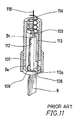
- the US-A 5,165,173 proposes an alternative construction as shown in FIG. 12 which corresponds to FIG. 5 of the US-A 5,165,173.
- a lock screw 128 is inserted into the drive shaft 103 and is in engagement with a female thread formed on an inner peripheral surface of the drive shaft 103, so that the upper portion of the blade B can be pressed or released by the axial movement of the lock screw 128.
- the screw 128 has an extension 129 extending upwardly from the screw 128 and having a semi-circular configuration in section.
- a screw rotating member 130 is also inserted into the drive shaft 103 and has a semi-circular configuration in section similar to the extension 129.
- the extension 129 and the screw rotating member 130 have confronting and mutually sliding flat surfaces. The screw rotating member 130 however is not threadably engaged with the drive shaft 103.
- the extension 129 is rotated together with the screw rotating member 130.
- the screw 128 is then rotated together with the extension 129, so that it is moved to press the upper end Bt of the blade B or to release the same.
- the screw rotating member 130 is rotated, it does not move in an axial direction. Therefore, only the extension 129 as well as the screw 128 is moved in the axial direction with its flat end slidably abutting on the flat surface of the extension 129.
- the above blade mounting device permits the blade B to be mounted and removed without using hand tools, the device can only applicable to the blade B having the bayonet lugs Ba. Therefore, this device is inconvenient in that the device cannot be applied to blades of different types.
- lug-type blade a blade having a through-hole formed on its upper end for inserting a protrusion which serves to prevent the blade from removal.
- hole-type blade a blade having a through-hole formed on its upper end for inserting a protrusion which serves to prevent the blade from removal.
- the blade of the latter type cannot be mounted on the device of the US-A 5,165,173 since it does not include any parts for engagement with the retention grooves 109.
- the amount of movement of the lock screw 128 for one rotation of the operation knob 137 can be increased by merely increasing pitch of the lock screw 128, and the above problem can be solved to some extent.
- the lock screw 128 tends to be loosened by vibration and other external forces, so that the mounting state of the blade B becomes unstable. Therefore, this solution is not desirable.
- EP 0 679 465 A1 which is prior art under Art. 54 (3) EPC, discloses a blade mounting device in a cutting tool comprising holder means, which are actuated by single thread means converting a rotational movement of an actuation member into an axial movement of the holder means.
- an object of the present invention to provide a blade mounting device which is improved in operability and allows to reliably and quickly fix and release a blade.
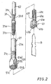
- FIG. 1 there is shown the overall view of a jig saw 1 incorporating a blade mounting device 11 of the present invention.
- the jig saw 1 has a housing 2 in which a motor having an output shaft 3 and acting as a drive source is accommodated.
- the rotation of the output shaft 3 of the motor is converted into a vertical reciprocal movement of a tubular rod 21 by means of a motion conversion mechanism 4.
- the rod 21 is supported on a front portion of the housing by means of bearings 2a and 2b, so that the rod 21 can be vertically slidably moved relative to the housing 2.
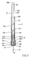
- the blade mounting device 11 generally includes the rod 21 as described above, an actuation rod 31 inserted into an axial hole 21a of the rod 21, a clamping member 41 for clamping a blade B, and a cap 51 which serves to open and close the clamping member 41.
- the actuation rod 31 is rotatable around the same axis as the rod 21 and is movable in the axial direction of the rod 21.
- the blade mounting device 11 is operable by rotating an operation knob 61 of an operation mechanism 60 positioned on the upper portion of the body 2.
- a roller guide 4a which forms the motion conversion mechanism 4 is secured to the rod 21 in a substantially central position of the rod 21 in its longitudinal direction.
- the roller guide 4a extends perpendicular to the axial direction of the rod 21.
- the axial hole 21a is formed throughout the length of the rod 21 and includes a left-hand thread hole 21c formed in substantially the central position in the axial direction of the axial hole 21a.
- the cap 51 is mounted on the lower end of the rod 21 as will be explained later.
- the diameter of the actuation rod 31 is determined such that the actuation rod 31 is insertable into the axial hole 21a of the rod 21.
- the actuation rod 31 has a left-hand male thread part 31a and a right-hand male thread part 31b having the same axis with each other.
- the right-hand thread part 31a has a diameter smaller than a diameter of the left-hand thread part 31b and is positioned on the lower side of the left-hand thread part 31b.
- the upper part of the actuation rod 31 positioned above the left-hand male thread part 31a has a semi-circular configuration in section to form a semi-circular rod part 31c.
- the actuation rod 31 thus constructed is inserted into the rod 21 from the upper side of the rod 21, so that the left-hand thread part 21c is engaged with the left-hand thread hole 21c of the axial hole 21a and that the right-hand thread part 31b is positioned downwardly beyond the left-hand thread hole 21c and is brought to engage a right-hand thread hole 41c formed in a cylindrical shaft portion 41a of the clamping claw 41.
- the clamping claw 41 has a fork-like configuration and includes a pair of claw portions 41b formed on the lower end of the cylindrical shaft portion 41a and opposed to each other in the diametrical direction of the cylindrical shaft Portion 41a.
- the claw portions 41b have flat surfaces confronting each other and extending in parallel to the axial direction of the cylindrical shaft portion 41a.
- the claw portions 41b have inclined surfaces 41e on the sides opposite to the flat surfaces.
- the inclined surfaces 41e are inclined relative to the axial direction of the cylindrical shaft portion 41a at the same inclination angle with each other, so that the distance between the inclined surfaces 41e is increased in the downward direction.
- a recess 41f is formed in the cylindrical shaft portion 41a at a position adjacent the claw portions 41b so as to provide resiliency in a direction to open the claw portions 41b.
- the cylindrical shaft portion 41a is axially movably inserted into the axial hole 21a of the rod 21 via a cylindrical tubular portion 51a of the cap 51.
- the right-hand thread hole 41c is formed in the upper end of the cylindrical shaft portion 41a.
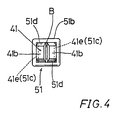
- the cap 51 has the cylindrical tubular portion 51a on its upper half part and has a rectangular tubular portion 51b on its lower half part (see FIG. 4).
- the cylindrical tubular portion 51a is closely fitted into the axial hole 21a at the lower end of the rod 21 and secured thereto.
- the rectangular tubular portion 51b receives claw portions 41b therein and has a pair of opposed inner walls having inclined surfaces 51c formed thereon and confronting the inclined surfaces 41e.
- the inclined surfaces 51c have the same inclination angle as the inclined surfaces 41e and slidably contact therewith, so that the claw portions 41b are moved to be opened and closed under the guide of the inclined surfaces 51c.
- a rotary rod 62 is positioned above the actuation rod 31 and has a semi-circular configuration in section corresponding to the configuration of the semi-circular rod portion 31c of the actuation rod 31.
- the rotary rod 62 is rotatable around the same axis as the actuation rod 31 and is inserted into the axial hole 21a of the rod 21, so that a flat surface 62a of the rotary rod 62 is in sliding contact with a flat surface 31d of the semi-circular rod portion 31c.
- the actuation rod 31 is rotated together with the rotary rod 62.
- the flat surfaces 62a and 31d merely slidably contact with each other, the actuation rod 31 can be movable in the axial direction independently of the rotary rod 62 which is fixed in position in the axial direction.
- the upper portion of the rotary rod 62 connected to the operation knob 61 via a torque limiter 70 and a lock plate 80.
- the torque limiter 70 disconnects the rotary rod 62 from the operation knob 61, so that the rotary rod 62 is prevented from damage.
- the lock plate 80 is slidably mounted on the operation knob 61 and is movable between a locking position and a releasing position in a direction perpendicular to the axial direction of the rotary rod 62. At the locking position shown in FIG. 1, the lock plate 80 disconnects the rotary rod 62 and the operation knob 61 from each other.
- the rotary rod 62 and the operation knob 61 are connected to each other for rotation together. Therefore, when the lock plate 80 is in the releasing position shown in FIG. 1, the potation of the operation knob 61 is not transmitted to the rotary rod 62, so that the blade mounting device 11 cannot be operated to release the blade B.
- the operation knob 61 also serves as a grip portion to be grasped by the operator during a cutting operation. Since in the releasing position, the lock plate 80 is pushed into the operation knob 61, the blade mounting device 11 is prevented from malfunction during the cutting operation with the operation knob 61 grasped by the operator.
- the actuation rod 31 as well as the rotary rod 62 is rotated, so that the blade mounting device 11 can be operated to clamp or release the blade B.
- the clamping member 41 In the state where the blade B is not mounted, the clamping member 41 is lowered from the position shown in FIG. 1 by a predetermined distance, so that the claw portions 41b are free from the inclined surfaces 51c of the cap 51 and are opened by virtue of the resilient force produced by the recess 41f.
- the operator inserts the head of the blade B between the claw portions 41b until the head abuts on the lower end of the cylindrical shaft portion 41a of the clamping claw 41 as shown in FIG. 1.
- the blade B" is inserted until the upper end of the blade B" abuts on the stepped portion formed in the cap 51 as shown in FIG. l(a). More specifically, the stepped portion is formed between the cylindrical portions 51a and 51b (see FIG. 3).
- the operation for inserting the blade B can be easily performed. Thereafter, the operator rotates the operation knob 61 in a right-hand direction, so that the actuation rod 31 is rotated together with the rotary rod 62 in the right-hand direction. As the actuation rod 31 is rotated in the right-hand direction, it is moved upwardly relative to the rod 21 by an anti-screwing movement of its left-hand thread part 31a relative to the left-hand thread hole 21c of the rod 21. With this movement of the actuation knob 31, the clamping claw 41 also moves upwardly together with the actuation rod 31.
- the claw portions 41b are prevented from rotation by the confronting inner walls 51d, so that the clamping claw 41 does not rotate with the actuation rod 31 although it moves vertically together with the actuation rod 31. Therefore, as the actuation rod 31 is rotated in the right-hand direction, the right-hand thread part 31b of the actuation rod 31 is screwed into the right-hand thread hole 41c of the clamping claw 41, so that the clamping claw 41 moves upwardly relative to the actuation rod 31.
- the clamping claw 41 is moved upwardly relative to the rod 21 by a distance corresponding to the sum of the distance of movement of the actuation rod 31 relative to the rod 21 and the distance of movement of the clamping claw 41 relative to the actuation rod 31.
- the clamping claw 41 is moved a greater distance by slightly rotating the operation knob 61, resulting in that the claw portions 41b can be quickly opened and closed.
- two thread parts 31a and 31b provided on the actuation pod 31 function not only merely a shifting mechanism of the clamping claw 41 but also function as a speed increasing mechanism for increasing the shifting distance of the clamping claw 41.
- Such a speed increasing function is performed not only when the clamping claw 41 is moved upwardly for clamping the blade B but also when the clamping claw 41 is moved downwardly for releasing the blade B as will be explained later.
- the claw portions 41b are gradually forced to be moved radially inwardly toward the closed position by the cooperation between their inclined surfaces 41e and the inclined surfaces 51c of the cap 51, so that the head of the blade B which has been inserted between the claw portions 41b are clamped and are fixed in position.
- the operator rotates the operation knob 61 in the reverse direction or a left-hand direction.
- the actuation rod 31 is rotated by the rotary rod 62 in the left-hand direction, so that the actuation rod 31 is moved downwardly relative to the rod 21 by a screwing movement of its left-hand thread part 31a relative to the left-hand thread hole 21c of the rod 21.
- the clamping claw 41 also moves downwardly together with the actuation knob 31.
- the clamping claw 41 moves downwardly relative to the actuation rod 31.
- the clamping claw 41 moves downwardly relative to the rod 21 by a distance which corresponds to the sum of the distance of the downward movement of the actuation rod 31 relative to the rod 21 and the distance of downward movement of the clamping claw 41 relative to the actuation rod 31.
- the claw portions 41b become free from the inclined surfaces 51c of the cap 51, so that they reliably return to move radially outwardly toward the open position by the resilient force which has been imparted by the recess 41f as described above.
- the blade B falls spontaneously. Otherwise, the operator can easily remove the blade B by pulling it downwardly.
- the clamping claw 41 can be moved relative to the rod 21 by a distance which corresponds to the distance of movement of the actuation rod 31 relative to the rod 21 and the distance of movement of the clamping claw 41 relative to the actuation rod 31. For this reason, by slightly rotating the operation knob 61, the claw portions 41b can be moved a great distance for clamping and releasing the blade B.
- the blade mounting device 11 of this embodiment is therefore improved in operability.
- the blade B can be mounted and removed by rotating the operation knob 61 for opening and closing the claw portions 41b, the mounting and releasing operation of the blade B can be made without using a special hand tool such as a screwdriver and a spanner.
- any type of blade such as the blade B" shown in FIG. 1(a) can be applied to the mounting device 11 as long as it has a head having a configuration insertable between the claw portions 41b.
- the mounting and removing operation of the blade B can be performed by only inserting the blade B into the claw portions 41b and by pulling out the blade B from the claw portions 41b, the operability or easiness in handling is improved.
- the mounting device 11 can cope with various kinds of blades having different thickness as long as the thickness is within a predetermined range.
- both the thread parts 31a and 31b on the actuation rod 31 may have different pitches from each other.
- both the thread parts 31a and 31b may have the same threaded direction while having different pitches from each other, so that the clamping claw 41 may be moved by a distance corresponding to the difference in pitches for each rotation.
- the inclining direction of the inclined surfaces 41e of the clamping claw 41 and the inclined surfaces 51c of the cap 51 is determined between the downwardly closing direction and downwardly opening direction.
- the thread part 31a is a right-hand thread having a pitch of 3 mm and the threaded part 31b is a right-hand thread having a pitch of 1 mm
- the clamping claw 41 moves downwardly by a distance of 2 mm. Therefore, in such a case, the inclined surfaces 41e of the clamping claw 41 and the inclined surfaces 51c of the cap 51 are inclined in the downwardly closing direction for closing the claw portions 41b to clamp the blade B.
- the blade B is clamped when the operation knob 61 is rotated in the right-hand direction, while the blade B is released when the operation knob 61 is rotated in the left-hand direction.
- the blade B may be clamped and released when the operation knob 61 is rotated in the left-hand direction and the right-hand direction, respectively.
- this embodiment includes two improvements, one of which is the provision of a clamping claw 41 for clamping the blade B in the direction of thickness through cooperation with the cap 51, and the other of which is the provision of two thread parts 31a and 31b on the actuation rod 31 for increasing the operation speed of the clamping claw 41.
- the above embodiment may be modified such that only one the improvement of the provision of two thread parts 31a and 31b has been incorporated.
- the clamping claw 41 and the cap 51 may be replaced by a holder mechanism which is operable to engage lugs formed on both lateral sides of a head of a blade and to press the head downwardly as disclosed in connection with the conventional mounting device in connection with FIGS. 11 and 12.
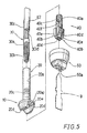
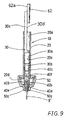
- a blade mounting device according to a second embodiment of the present invention will now be explained with reference to FIGS. 5 to 9.
- a blade mounting device 10 of this embodiment is a modification of the blade mounting device 11 of the first embodiment and mainly includes a rod 20, an actuation rod 31, a clamping claw 40 and a cap 50 corresponding to the rod 21, the actuation rod 31, the clamping claw 41 and the cap 51 of the first embodiment, respectively.
- This embodiment is different from the first embodiment mainly in the following points:
- the rod 20 is reciprocally driven in the same manner as the rod 21 of the first embodiment and includes a an axial hole 20a formed therein.
- the axial hole 20a has right-hand thread hole 20c formed in a positioned adjacent the lower end of the rod 20.
- a circular flange 20e is formed on the lower end of the rod 20 and includes a pair of diametrically confronting support walls 20d extending downwardly from the flange 20e and spaced from each other by a predetermined distance.
- the axial hole 20a is opened in the center of the flange 20e and between the support walls 20d.
- the clamping claw 40 has a cylindrical shaft portion 40a having one end on which a pair of confronting claw portions 40b are formed in a fork like manner.
- the claw portions 40b have flat surfaces on the sides confronting each other.
- the inclined surfaces 40d are formed on the opposite sides of the flat surfaces and are inclined relative to the axial direction of the cylindrical shaft portion 40a such that the distance between the inclined surfaces 40d decreases in the downward direction.
- a recess 40f is formed on the cylindrical shaft portion 40e at a position between the claw portions 40b to provide resiliency of the claw portions 40b.
- a slit 40d is formed in each of the claw portions 40b in a central position in a widthwise direction and extending in the longitudinal direction of the claw portion 40b.
- the slit 40d serves to provide further resiliency of the claw portions 40b since each of the claw portions 40b are divided into substantially two parts.
- the width of the claw portions 40b is determined such that the claw portions 40b are insertable between the support walls 20d.
- the cylindrical shaft portion 40a is axially slidably inserted into the axial hole 20a of the rod 20 and has a left-hand thread hole 40c formed in the upper end. With the cylindrical shaft portion 40a axially movably inserted into the axial hole 20a of the rod 20 and with the claw portions 40b inserted between the support walls 20d. the left-hand thread 30b of the actuation rod 30 is screwed into the left-hand thread 40c of the cylindrical shaft portion 40c.
- the actuation rod 30 having the right-hand thread part 30a and the left-hand thread part 30b on the same axis is inserted into the rod 20.
- the left-hand thread part 30b has a diameter smaller than the diameter of the right-hand thread part 30a and is positioned downwardly thereof.
- a semi-circular rod portion 30c corresponding to the semicircular rod portion 31c of the first embodiment is formed on an upper portion of the actuation rod 30.
- the actuation rod 30 is inserted into the axial hole 20a of the rod 20 from the upper side, and the right-hand thread part 30 is engaged with the right-hand thread hole 20c such that the left-hand thread part 30b is positioned beyond the thread hole 20c and is screwed into the left-hand thread hole 40c of the clamping claw 40c.
- the clamping claw 40 is moved downwardly by a distance corresponding to the sum of the distance of movement of the actuation rod 30 relative to the rod 20 and the distance of movement of the clamping claw 40 relative to the actuation rod 30, so that the clamping claw 40 is moved a greater distance for quickly clamping the blade B by slightly rotating the actuation rod 30.
- the cap 50 serves to hold the clamping claw 40 between the support walls 20d at the lower end of the rod 20.
- the cap 50 has substantially cup-shaped configuration to cover the lower portion of the clamping claw 40.
- An inserting hole 50a is formed in the central portion of the cap 50 for inserting the head of the blade B.
- the cap 50 has an open top which is positioned on the opposite side of the inserting hole 50a and is closed by the flange 20e of the rod 20.
- a stop ring 50b is interposed between the peripheral portion of the upper surface of the flange 20e and an inner peripheral portion of the open top of the cap 50, so that the cover 50 is mounted on the rod 20 while the cover 50 accommodates the support walls 20d and the clamping claw 40 therewithin.
- the inclined surfaces 50c are formed in the cover 50 in a position adjacent the inserting hole 50a and confront each other.
- the inclined surfaces 50c are inclined in the same direction as the inclined surfaces 40e of the claw portions 40b, so that the distance between the inclined surfaces 40e are decreased in the downward direction.
- the claw portions 40b are forced to be closed when the clamping claw 40 moves downwardly, and the claw portions 40b resiliently recover the open position when the clamping claw 40 moves upwardly.
- the mounting device 10 When the blade B is not mounted, the mounting device 10 is in a position shown in FIG. 6. where the clamping claw 40 is moved upwardly and the claw portions 40b are opened. In this position, the blade B is inserted between the claw portions 40b through the inserting hole 50a. Then the operation mechanism 60 is operated to rotate the actuation rod 30 in the right-hand direction, so that the clamping claw 40 is moved downwardly relative to rod 20 as described above. Here, the rotation of the clamping claw 40 is prevented by the support walls 20d. As the clamping claw 40 is thus moved downwardly, the claw portions 40b are moved to be closed through cooperation between the inclined surfaces 40e and 50c, so that the head of the blade B is clamped as shown in FIGS. 7 and 8.
- the operation mechanism 60 is operated to rotate the actuation rod 30 in the left-hand direction, so that the clamping claw 40 is moved upwardly, and that the claw portions 40b resiliently recovers the open position.
- the blade mounting device 10 can cope with various kind of blades having different thickness as described in connection with the blade clamping device 11 of the first embodiment.
- FIG 9 shows the clamping state of a blade B' which has a smaller thickness than the blade B shown in FIGS. 7 and 8.
- the cap 51 of the first embodiment has a rectangular tubular configuration and is fixedly mounted on the rod 21.
- the cap 51 does not require a mounting member such as the stop ring 50b of the second embodiment. Therefore, the mounting device 11 is compact and simple in construction and uses a reduced number of parts. Further the mounting device 11 can be easily assembled and can be manufactured at lower cost.
- the cap 51 has two pairs of confronting walls, one forming the inclined surfaces 51c and the other constituting the inner walls 51d with which lateral surfaces of each claw portion 41b slidably contact.
- the inner walls 51d serve as the support walls 20d of the second embodiment. Therefore, the construction of the mounting device 11 of the first embodiment is further simplified.
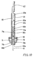
- This embodiment is a modification of the second embodiment. Like members are given the same reference numerals and their description will not be repeated.
- a claw 70 and a claw 71 which are separated from each other are incorporated to clamp and release the blade B through movement of the claws 70 and 71 in opposite directions.
- the claws 70 and 71 correspond to the claw portions 40b of the clamping claw 40 of the second embodiment if the claw portions 40b are divided along the central axis of the cylindrical shaft portion 40a.
- each of the claws 70 and 71 has a semi-cylindrical tubular upper part.
- a right-hand thread hole 70a having a semi-circular configuration in section is formed in the upper part of the claw 70.
- a left-hand thread hole 71a having a semi-circular configuration in section is formed in the upper part of the claw 71 and is positioned downwardly of the thread hole 70a.
- An actuation rod 80 has a right-hand thread part 80a in engagement with the right-hand thread hole 20c of the rod 20.
- a right-hand thread part 80b is formed on the actuation rod 80 in a position downwardly of the thread part 80a and is in engagement only with the right-hand thread hole 70a of the claw 70.
- the claw 70 includes a lower portion having an inclined surface 70b formed on an outer surface opposite to the claw 71.
- the inclined surface 70b is downwardly outwardly inclined relative to the axis of the rod 20 or inclined in the open direction.
- the claw 71 includes a lower portion having an inclined surface 71b that is formed on an outer surface opposite to the claw 70. Similar to the inclined surfaces 40e of the second embodiment, the inclined surface 71b is downwardly inwardly inclined relative to the axis of the rod 20.
- a cap 90 has inclined surfaces 90a and 90b which face the inclined surfaces 70b and 71b, respectively, and which are inclined in the same manner as these surfaces 70b and 71, respectively, so that the inclined surface 70b of the claw 70 slidably contacts the inclined surface 90a, while the inclined surface 71b of the claw 71 slidably contacts the inclined surface 90b.
- the actuation rod 80 when the actuation rod 80 is rotated in the right-hand direction in the same manner as the above embodiments, the actuation rod 80 is moved downwardly through the screwing movement of the right-hand thread part 80a into the right-hand thread hole 20c, while the claw 70 positioned on the right side in FIG. 10 is moved upwardly relative to the actuation rod 80.
- the pitch (lead) of the right-hand thread part 80b is determined to have a greater distance than the pitch of the right-hand thread part 80a, so that the claw 70 moves upwardly relative to the rod 20.
- the claw 70 is moved toward the closing position through cooperation between the inclined surface 70b and the inclined surface 90a of the cap 90.
- the other hand On the other hand.
- the claw 71 positioned on the left side is moved downwardly relative to the actuation rod 80 by the anti-screwing movement of the left-hand thread part 80c against the left-hand thread hole 71a, so that the claw 71 is moved downwardly by a distance corresponding to the sum of the moving distance of the actuation rod 80 relative to the rod 20 and the moving distance of the claw 71 relative to the actuation rod 80.
- the claw 71 is moved downwardly, the claw 71 is moved toward the closing position through cooperation between the inclined surface 71b and the inclined surface 90b of the cap 90.
- the claws 70 and 71 are closed by slightly rotating the actuation rod 80, so that the blade B inserted between the claws 70 and 71 are clamped.
- the blade B can be mounted and released without using a special hand tool , the device can cope with various kinds of blades, and the mounting and removing operation of the blade can be easily performed.
- two thread parts formed on the actuation rod may have different pitches from each other, and both the thread parts may have the same threaded direction while having different pitches from each other.
- the blade B may be clamped and released when the operation knob 61 is rotated in the left-hand direction and the right-hand direction, respectively.
- the blade mounting device may include only the improvement of the provision of the two thread parts on the actuation mechanism.
Claims (8)
- Blattmontagevorrichtung (11) zum Montieren eines Blattes (B) auf einem bewegbaren Teil (20; 21) eines Schneidwerkzeugs, das in einer vorbestimmten Bewegung für einen Schneidtrieb bewegt wird, mit
einem Haltemittel (40; 41), das auf dem bewegbaren Teil (20; 21) montiert ist und relativ zu dem bewegbaren Teil (20; 21) in einer axialen Richtung zwischen einer ersten Position zum Halten des Blattes (B) und einer zweiten Position zum Freigeben des Blattes bewegbar ist, und
einem Betätigungsmittel (51, 60), das durch einen Bediener zum Betätigen des Haltemittels betätigbar ist,
wobei das Betätigungsmittel (50; 51, 60)
ein Betätigungsteil (30; 31), das durch den Bediener zur Drehung betätigbar ist, und
ein Gewindemittel (20c, 30a, 30b, 40a; 21c, 31a, 31b, 41c) zum Wandeln der Drehbewegung des Betätigungsteils (30, 31) in eine Axialbewegung des Haltemittels (40; 41), aufweist,
wobei das Gewindemittel
ein erstes Gewindemittel (20c, 30a; 21c, 31a), das zwischen dem Betätigungsteil (30; 31) und dem bewegbaren Teil (20; 21) angeordnet ist, zum Wandeln der Drehung des Betätigungsteils (30; 31) in die Axialbewegung des Betätigungsteils (30; 31) relativ zu dem bewegbaren Teil (20, 21), und
ein zweites Gewindemittel (30b, 40a; 31b, 41c), das zwischen dem Betätigungsteil (30, 31) und dem Halteteil (40; 41) angeordnet ist, zum Wandeln der Drehung des Betätigungsteils (30; 31) in die Axialbewegung des Haltemittels (40; 41) relativ zu dem Betätigungsteil (30; 31) aufweist. - Blattmontagevorrichtung nach Anspruch 1, bei der das Schneidwerkzeug ein sich hin- und herbewegendes Schneidwerkzeug ist, das einen Körper (2) und einen Motor zum linear hin- und herbewegbaren Antreiben des bewegbaren Teils (20; 21) in seiner axialen Richtung und ein Drehteil (61), das durch den Bediener manuell drehbar ist, aufweist, wobei das Drehteil mit dem Betätigungsteil (30; 31) betreibbar so verbunden ist, daß das Betätigungsteils (30; 31) relativ zu dem Drehteil (61) in der Axialrichtung des bewegbaren Teils gleitend bewegbar ist, während das Betätigungsteil (30; 31) zusammen mit dem Drehteil drehbar ist.
- Blattmontagevorrichtung nach Anspruch 1 oder 2, bei der das erste Gewindemittel (20c; 30a; 21c,31c) und das zweite Gewindemittel (30b; 40a; 31b, 31c) zum Wandeln einer Drehung des Betätigungsteils (30; 31) in die Axialbewegung des Betätigungsteils (30; 31) und der Klauen (40b, 41b) in derselben Richtung betätigbar sind.
- Blattmontagevorrichtung nach Anspruch 1,2 oder 3, bei der eines der ersten und zweiten Gewindemittel (20c, 30a, 30b, 40a; 21c, 31a, 31b, 41c) ein Rechtsgewinde ist und das andere der ersten und zweiten Gewindemittel ein Linksgewinde ist.
- Blattmontagevorrichtung nach einem der Ansprüche 1 bis 4, bei der
das Betätigungsteil (30,31) eine röhrenförmige Konfiguration aufweist,
das bewegbare Teil (20; 21) ein röhrenförmiger Stab ist zum Empfangen des Betätigungsteils (30, 31) koaxial mit diesem,
das Haltemittel (40; 41) einen Schaft (40a, 41a) aufweist, der axial gleitend bewegbar in dem röhrenförmigen Stab eingesetzt ist und ein axiales Loch aufweist,
das erste Gewindemittel (20c, 30a; 21c, 31a) ein erstes Außengewinde (30b,31b), das auf einer äußeren Oberfläche des Betätigungsteils (30; 31) ausgebildet ist, und ein erstes Gewindeloch (20c; 21c), das in dem röhrenförmigen Stab ausgebildet ist und in Eingriff mit dem ersten Außengewinde ist, aufweist, und
das zweite Gewindemittel (30b, 40a; 31a, 41c) ein zweites Außengewinde (30b; 31b), das axial gegenüber dem ersten Außengewinde (30a; 31a) versetzt ist, und ein zweites Gewindeloch (40a; 41c), das in dem axialen Loch des Schaftes des Haltemittels (41) ausgebildet ist und in Eingriff mit dem zweiten Außengewinde ist, aufweist. - Blattmontagevorrichtung nach Anspruch 5, bei der das Haltemittel (40; 41) ein erstes Halteteil (40b; 41b) und ein zweites Halteteil (40b; 41b), die miteinander zum Klemmen des Blattes (B) zusammenarbeiten, aufweist, und bei der das erste Halteteil und das zweite Halteteil miteinander durch den Schaft (40; 41a) verbunden sind.
- Blattmontagevorrichtung nach Anspruch 1, bei der
das Haltemittel ein erstes Halteteil und ein zweites Halteteil (71) aufweist, die miteinander zum Klemmen des Blattes (B) zusammenarbeiten und unabhängig voneinander relativ zu dem bewegbaren Teil axial gleitend bewegbar sind,
wobei das zweite Gewindemittel
ein erstes Haltergewindemittel (70a) zum Wandeln der Drehung des Betätigungsteils in eine axiale Bewegung des ersten Halteteils (70) und
ein zweites Haltergewindemittel (71 a) zum Wandeln der Drehung des Betätigungsteils in eine axiale Bewegung des zweiten Halteteils (71) aufweist,
wobei das erste Haltergewindemittel (70a) und das zweite Haltergewindemittel (71a) zum Wandeln der Drehung des Betätigungsteils in die axiale Bewegung des ersten und des zweiten Halterteils in zueinander entgegengesetzten Richtungen betätigbar sind. - Blattmontagevorrichtung nach Anspruch 7, bei der das erste Haltergewindemittel (70a) des zweiten Gewindemittels eine Ganghöhe, die größer als eine Ganghöhe des ersten Gewindemittels ist, aufweist.
Applications Claiming Priority (5)
| Application Number | Priority Date | Filing Date | Title |
|---|---|---|---|
| JP29980494A JP3494721B2 (ja) | 1994-12-02 | 1994-12-02 | 往復動切断工具のブレード取付け装置 |
| JP29980494 | 1994-12-02 | ||
| JP32020994A JP3215275B2 (ja) | 1994-12-22 | 1994-12-22 | 往復動切断工具のブレード取付け装置 |
| JP32020994 | 1994-12-22 | ||
| EP95118896A EP0714730A3 (de) | 1994-12-02 | 1995-11-30 | Schneidwerkzeugaufspannvorrichtung |
Related Parent Applications (1)
| Application Number | Title | Priority Date | Filing Date |
|---|---|---|---|
| EP95118896.0 Division | 1995-11-30 |
Publications (3)
| Publication Number | Publication Date |
|---|---|
| EP0930121A2 EP0930121A2 (de) | 1999-07-21 |
| EP0930121A3 EP0930121A3 (de) | 1999-10-27 |
| EP0930121B1 true EP0930121B1 (de) | 2002-04-24 |
Family
ID=26562081
Family Applications (2)
| Application Number | Title | Priority Date | Filing Date |
|---|---|---|---|
| EP99104084A Expired - Lifetime EP0930121B1 (de) | 1994-12-02 | 1995-11-30 | Schneidwerkzeugaufspannvorrichtung |
| EP95118896A Withdrawn EP0714730A3 (de) | 1994-12-02 | 1995-11-30 | Schneidwerkzeugaufspannvorrichtung |
Family Applications After (1)
| Application Number | Title | Priority Date | Filing Date |
|---|---|---|---|
| EP95118896A Withdrawn EP0714730A3 (de) | 1994-12-02 | 1995-11-30 | Schneidwerkzeugaufspannvorrichtung |
Country Status (3)
| Country | Link |
|---|---|
| US (1) | US5661909A (de) |
| EP (2) | EP0930121B1 (de) |
| DE (1) | DE69526528T2 (de) |
Families Citing this family (23)
| Publication number | Priority date | Publication date | Assignee | Title |
|---|---|---|---|---|
| EP0727270B1 (de) * | 1995-02-15 | 2002-05-22 | Makita Corporation | Sägeblattaufspannvorrichtung für Schneidwerkzeuge |
| US6944959B2 (en) | 1995-06-09 | 2005-09-20 | Black & Decker Inc. | Clamping arrangement for receiving a saw blade in multiple orientations |
| US7325315B2 (en) | 1995-06-09 | 2008-02-05 | Black & Decker Inc. | Clamping arrangement for receiving a saw blade in multiple orientations |
| EP0792712B1 (de) * | 1996-03-01 | 2002-05-08 | Black & Decker Inc. | Motorisierte Stichsäge |
| JP2000225517A (ja) * | 1998-12-04 | 2000-08-15 | Hitachi Koki Co Ltd | 往復動工具 |
| JP4150991B2 (ja) * | 2000-02-25 | 2008-09-17 | Smc株式会社 | トルクリミッター付き電動ハンド |
| JP3995895B2 (ja) | 2000-05-16 | 2007-10-24 | 株式会社マキタ | 往復動切断工具のブレード取り付け装置 |
| US6735876B2 (en) | 2001-03-01 | 2004-05-18 | Makita Corporation | Blade clamps suitable for reciprocating power tools |
| US6715211B1 (en) * | 2002-02-26 | 2004-04-06 | Chih-Sung Chi | Mounting and fixing structure of a handle and a tool head of a hand tool |
| BR8301911Y1 (pt) * | 2003-03-24 | 2014-03-04 | Starrett Ind E Com Ltda | Disposição construtiva em serra |
| US7871080B2 (en) * | 2004-01-16 | 2011-01-18 | Robert Bosch Gmbh | Tool-less blade clamping apparatus for a reciprocating tool |
| US20050192585A1 (en) * | 2004-02-27 | 2005-09-01 | Medtronic, Inc. | Surgical saw collet with closed drive ring |
| US7344113B2 (en) * | 2006-02-27 | 2008-03-18 | Gau Woei Super Hard Tool Co., Ltd. | Tool holder having a clamping hole |
| US8230607B2 (en) | 2008-05-09 | 2012-07-31 | Milwaukee Electric Tool Corporation | Keyless blade clamp for a power tool |
| JP5558214B2 (ja) * | 2010-06-08 | 2014-07-23 | 株式会社マキタ | 往復動切断工具のブレード取り付け装置 |
| US9156097B2 (en) * | 2012-03-20 | 2015-10-13 | Milwaukee Electric Tool Corporation | Reciprocating saw blade clamp |
| DE102012206036A1 (de) * | 2012-04-13 | 2013-10-17 | Robert Bosch Gmbh | Werkzeugmaschinenspannvorrichtung |
| US10369641B2 (en) * | 2016-04-20 | 2019-08-06 | Jpw Industries Inc. | Combined blade clamp and tensioner for scroll saw |
| TWM537946U (zh) * | 2016-06-20 | 2017-03-11 | Lu Can-Yang | 往復式工具結構 |
| US10843363B2 (en) * | 2017-11-10 | 2020-11-24 | Urschel Laboratories, Inc. | Knife assemblies and cutting apparatuses comprising the same |
| CN110405276B (zh) * | 2019-08-07 | 2024-02-09 | 宁波汉浦工具有限公司 | 一种两用锯刀 |
| CN110923121B (zh) * | 2019-12-20 | 2021-07-02 | 华中农业大学 | 单孢分离装置、单孢分离显微镜以及单孢分离方法 |
| US11679443B1 (en) * | 2022-01-25 | 2023-06-20 | Lemco Products LLC | Apparatus for a quick release cutting device blade assembly |
Family Cites Families (20)
| Publication number | Priority date | Publication date | Assignee | Title |
|---|---|---|---|---|
| US2736203A (en) * | 1956-02-28 | shore | ||
| CH278344A (de) * | 1949-10-08 | 1951-10-15 | Gassler Max | Werkzeugkopf für Bohrmaschinen. |
| US2670963A (en) * | 1950-11-02 | 1954-03-02 | Leonard C Osborn | Chuck |
| GB907520A (en) * | 1960-06-17 | 1962-10-03 | Thos R Ellin Footprint Works L | Improvements in or relating to pad and like saws |
| US3795980A (en) * | 1972-11-29 | 1974-03-12 | Singer Co | Chuck device for sabre saws |
| DE7513910U (de) * | 1975-04-30 | 1976-11-04 | Scintilla Ag, Solothurn (Schweiz) | Zusatzgriff, insbesondere fuer kraftwerkzeuge |
| US4020555A (en) * | 1976-04-12 | 1977-05-03 | Pevrick Engineering Co., Inc. | Connecting mechanism for a saw blade |
| DE3245420A1 (de) * | 1982-12-08 | 1984-06-14 | Robert Bosch Gmbh, 7000 Stuttgart | Motorbetriebene stichsaege |
| DE3245359A1 (de) * | 1982-12-08 | 1984-06-14 | Robert Bosch Gmbh, 7000 Stuttgart | Saege, insbesondere motorisch angetriebene handstichsaege |
| DE3247178A1 (de) * | 1982-12-21 | 1984-06-28 | Robert Bosch Gmbh, 7000 Stuttgart | Stichsaege mit einer befestigungsvorrichtung fuer ein flaches stichsaegeblatt |
| US4602798A (en) * | 1984-04-23 | 1986-07-29 | James Wettstein | Collet arbor for application to turning and milling procedures |
| US4570517A (en) * | 1984-09-04 | 1986-02-18 | Souza John A | Self-interlocking split saw blade |
| CA1223793A (en) * | 1986-06-23 | 1987-07-07 | Jacques Ducharme | Scoring saw |
| WO1989008524A1 (en) * | 1988-03-15 | 1989-09-21 | Robert Bosch Gmbh | Jigsaw |
| CH674955A5 (de) * | 1988-12-20 | 1990-08-15 | Tdm S A | |
| DE4138986A1 (de) * | 1991-11-27 | 1993-06-03 | Atlas Copco Elektrowerkzeuge | Spanneinrichtung fuer eine stichsaegemaschine |
| US5421232A (en) * | 1992-09-26 | 1995-06-06 | Black & Decker Inc. | Reciprocating saw |
| DE4313718C2 (de) * | 1993-04-27 | 1997-04-10 | Bernd Hoeschele | Vorrichtung zur Halterung eines Sägeblattes |
| JP3429027B2 (ja) * | 1993-06-30 | 2003-07-22 | 株式会社長田中央研究所 | チャック機構 |
| DE4344129A1 (de) * | 1993-12-23 | 1995-06-29 | Bosch Gmbh Robert | Kraftgetriebene Schwertsäge |
-
1995
- 1995-11-30 EP EP99104084A patent/EP0930121B1/de not_active Expired - Lifetime
- 1995-11-30 US US08/565,722 patent/US5661909A/en not_active Expired - Lifetime
- 1995-11-30 DE DE69526528T patent/DE69526528T2/de not_active Expired - Lifetime
- 1995-11-30 EP EP95118896A patent/EP0714730A3/de not_active Withdrawn
Also Published As
| Publication number | Publication date |
|---|---|
| EP0714730A2 (de) | 1996-06-05 |
| EP0930121A3 (de) | 1999-10-27 |
| US5661909A (en) | 1997-09-02 |
| DE69526528D1 (de) | 2002-05-29 |
| EP0714730A3 (de) | 1997-04-23 |
| DE69526528T2 (de) | 2002-12-05 |
| EP0930121A2 (de) | 1999-07-21 |
Similar Documents
| Publication | Publication Date | Title |
|---|---|---|
| EP0930121B1 (de) | Schneidwerkzeugaufspannvorrichtung | |
| EP0554929B1 (de) | Spannzange für eine Klinge | |
| EP0582326B1 (de) | Sägeblattfestspannvorrichtung | |
| EP0727270B1 (de) | Sägeblattaufspannvorrichtung für Schneidwerkzeuge | |
| USRE33335E (en) | Device for attaching a tool | |
| US6276065B1 (en) | Blade attaching and detaching mechanism for a saber saw | |
| EP1174203B1 (de) | Handbetätigtes Spannfutter | |
| CN106737446B (zh) | 手持式工具及其夹紧装置 | |
| EP2070659B1 (de) | Elektrowerkzeug mit Spindelarretierung | |
| US5794352A (en) | Saw blade clamping arrangement for a power tool | |
| EP0693341A1 (de) | Selbstklemmende Klingenhalterung | |
| GB1597239A (en) | Clamping arrangement | |
| US8327550B2 (en) | Blade clamp for reciprocating saw | |
| JP4020974B2 (ja) | 電動工具のための締付け機構 | |
| EP2247402B1 (de) | Fusssperranordnung für ein hubkolbenwerkzeug | |
| EP0810050B1 (de) | Sägeblattaufspannvorrichtung für ein motorisiertes Werkzeug | |
| CA2493219C (en) | Quick-connect chuck mechanism | |
| CN107999824B (zh) | 动力工具 | |
| GB1565566A (en) | Devices for rotating screw caps on containers | |
| SE519166C2 (sv) | Kabelskalningsverktyg | |
| EP0940210A1 (de) | Sägeblattspannvorrichtung und Säge versehen mit dieser Vorrichtung | |
| JP3494721B2 (ja) | 往復動切断工具のブレード取付け装置 | |
| JP3215275B2 (ja) | 往復動切断工具のブレード取付け装置 | |
| KR100634720B1 (ko) | 로드 안테나 고정 장치 | |
| SE519152C2 (sv) | Kabelskalningsverktyg |
Legal Events
| Date | Code | Title | Description |
|---|---|---|---|
| PUAI | Public reference made under article 153(3) epc to a published international application that has entered the european phase |
Free format text: ORIGINAL CODE: 0009012 |
|
| 17P | Request for examination filed |
Effective date: 19990318 |
|
| AC | Divisional application: reference to earlier application |
Ref document number: 714730 Country of ref document: EP |
|
| AK | Designated contracting states |
Kind code of ref document: A2 Designated state(s): DE FR GB |
|
| PUAL | Search report despatched |
Free format text: ORIGINAL CODE: 0009013 |
|
| AK | Designated contracting states |
Kind code of ref document: A3 Designated state(s): DE FR GB |
|
| 17Q | First examination report despatched |
Effective date: 20001228 |
|
| GRAG | Despatch of communication of intention to grant |
Free format text: ORIGINAL CODE: EPIDOS AGRA |
|
| GRAG | Despatch of communication of intention to grant |
Free format text: ORIGINAL CODE: EPIDOS AGRA |
|
| GRAH | Despatch of communication of intention to grant a patent |
Free format text: ORIGINAL CODE: EPIDOS IGRA |
|
| REG | Reference to a national code |
Ref country code: GB Ref legal event code: IF02 |
|
| GRAH | Despatch of communication of intention to grant a patent |
Free format text: ORIGINAL CODE: EPIDOS IGRA |
|
| GRAA | (expected) grant |
Free format text: ORIGINAL CODE: 0009210 |
|
| AC | Divisional application: reference to earlier application |
Ref document number: 714730 Country of ref document: EP |
|
| AK | Designated contracting states |
Kind code of ref document: B1 Designated state(s): DE FR GB |
|
| REG | Reference to a national code |
Ref country code: GB Ref legal event code: FG4D |
|
| REF | Corresponds to: |
Ref document number: 69526528 Country of ref document: DE Date of ref document: 20020529 |
|
| ET | Fr: translation filed | ||
| PLBE | No opposition filed within time limit |
Free format text: ORIGINAL CODE: 0009261 |
|
| STAA | Information on the status of an ep patent application or granted ep patent |
Free format text: STATUS: NO OPPOSITION FILED WITHIN TIME LIMIT |
|
| 26N | No opposition filed |
Effective date: 20030127 |
|
| PGFP | Annual fee paid to national office [announced via postgrant information from national office to epo] |
Ref country code: FR Payment date: 20141110 Year of fee payment: 20 Ref country code: GB Payment date: 20141126 Year of fee payment: 20 Ref country code: DE Payment date: 20141125 Year of fee payment: 20 |
|
| REG | Reference to a national code |
Ref country code: DE Ref legal event code: R071 Ref document number: 69526528 Country of ref document: DE |
|
| REG | Reference to a national code |
Ref country code: GB Ref legal event code: PE20 Expiry date: 20151129 |
|
| PG25 | Lapsed in a contracting state [announced via postgrant information from national office to epo] |
Ref country code: GB Free format text: LAPSE BECAUSE OF EXPIRATION OF PROTECTION Effective date: 20151129 |