EP0929433B1 - Verfahren und vorrichtung zur entziehung von stossenergie insbesondere in selbsttätigen kupplungen von schienenfahrzeugen - Google Patents
Verfahren und vorrichtung zur entziehung von stossenergie insbesondere in selbsttätigen kupplungen von schienenfahrzeugen Download PDFInfo
- Publication number
- EP0929433B1 EP0929433B1 EP98917820A EP98917820A EP0929433B1 EP 0929433 B1 EP0929433 B1 EP 0929433B1 EP 98917820 A EP98917820 A EP 98917820A EP 98917820 A EP98917820 A EP 98917820A EP 0929433 B1 EP0929433 B1 EP 0929433B1
- Authority
- EP
- European Patent Office
- Prior art keywords
- length
- force
- takes place
- piston rod
- elastomer
- Prior art date
- Legal status (The legal status is an assumption and is not a legal conclusion. Google has not performed a legal analysis and makes no representation as to the accuracy of the status listed.)
- Expired - Lifetime
Links
- 238000000034 method Methods 0.000 title claims description 10
- 230000008878 coupling Effects 0.000 title claims description 4
- 238000010168 coupling process Methods 0.000 title claims description 4
- 238000005859 coupling reaction Methods 0.000 title claims description 4
- 239000006096 absorbing agent Substances 0.000 claims description 25
- 229920001971 elastomer Polymers 0.000 claims description 21
- 239000000806 elastomer Substances 0.000 claims description 21
- 230000007423 decrease Effects 0.000 claims description 18
- 238000000605 extraction Methods 0.000 claims description 3
- 239000012530 fluid Substances 0.000 claims 1
- 230000000284 resting effect Effects 0.000 claims 1
- 230000035939 shock Effects 0.000 description 21
- 238000003780 insertion Methods 0.000 description 8
- 230000037431 insertion Effects 0.000 description 8
- 238000006073 displacement reaction Methods 0.000 description 5
- 238000010521 absorption reaction Methods 0.000 description 1
- 239000007788 liquid Substances 0.000 description 1
- 230000003068 static effect Effects 0.000 description 1
Images
Classifications
-
- B—PERFORMING OPERATIONS; TRANSPORTING
- B61—RAILWAYS
- B61G—COUPLINGS; DRAUGHT AND BUFFING APPLIANCES
- B61G11/00—Buffers
- B61G11/16—Buffers absorbing shocks by permanent deformation of buffer element
-
- F—MECHANICAL ENGINEERING; LIGHTING; HEATING; WEAPONS; BLASTING
- F16—ENGINEERING ELEMENTS AND UNITS; GENERAL MEASURES FOR PRODUCING AND MAINTAINING EFFECTIVE FUNCTIONING OF MACHINES OR INSTALLATIONS; THERMAL INSULATION IN GENERAL
- F16F—SPRINGS; SHOCK-ABSORBERS; MEANS FOR DAMPING VIBRATION
- F16F1/00—Springs
- F16F1/36—Springs made of rubber or other material having high internal friction, e.g. thermoplastic elastomers
- F16F1/42—Springs made of rubber or other material having high internal friction, e.g. thermoplastic elastomers characterised by the mode of stressing
- F16F1/44—Springs made of rubber or other material having high internal friction, e.g. thermoplastic elastomers characterised by the mode of stressing loaded mainly in compression
- F16F1/445—Springs made of rubber or other material having high internal friction, e.g. thermoplastic elastomers characterised by the mode of stressing loaded mainly in compression the spring material being contained in a generally closed space
-
- F—MECHANICAL ENGINEERING; LIGHTING; HEATING; WEAPONS; BLASTING
- F16—ENGINEERING ELEMENTS AND UNITS; GENERAL MEASURES FOR PRODUCING AND MAINTAINING EFFECTIVE FUNCTIONING OF MACHINES OR INSTALLATIONS; THERMAL INSULATION IN GENERAL
- F16F—SPRINGS; SHOCK-ABSORBERS; MEANS FOR DAMPING VIBRATION
- F16F7/00—Vibration-dampers; Shock-absorbers
- F16F7/12—Vibration-dampers; Shock-absorbers using plastic deformation of members
- F16F7/123—Deformation involving a bending action, e.g. strap moving through multiple rollers, folding of members
-
- F—MECHANICAL ENGINEERING; LIGHTING; HEATING; WEAPONS; BLASTING
- F16—ENGINEERING ELEMENTS AND UNITS; GENERAL MEASURES FOR PRODUCING AND MAINTAINING EFFECTIVE FUNCTIONING OF MACHINES OR INSTALLATIONS; THERMAL INSULATION IN GENERAL
- F16F—SPRINGS; SHOCK-ABSORBERS; MEANS FOR DAMPING VIBRATION
- F16F7/00—Vibration-dampers; Shock-absorbers
- F16F7/12—Vibration-dampers; Shock-absorbers using plastic deformation of members
- F16F7/127—Vibration-dampers; Shock-absorbers using plastic deformation of members by a blade element cutting or tearing into a quantity of material; Pultrusion of a filling material
-
- F—MECHANICAL ENGINEERING; LIGHTING; HEATING; WEAPONS; BLASTING
- F16—ENGINEERING ELEMENTS AND UNITS; GENERAL MEASURES FOR PRODUCING AND MAINTAINING EFFECTIVE FUNCTIONING OF MACHINES OR INSTALLATIONS; THERMAL INSULATION IN GENERAL
- F16F—SPRINGS; SHOCK-ABSORBERS; MEANS FOR DAMPING VIBRATION
- F16F2236/00—Mode of stressing of basic spring or damper elements or devices incorporating such elements
- F16F2236/04—Compression
- F16F2236/045—Compression the spring material being generally enclosed
Definitions
- the invention relates to a method and a device for extracting impact energy especially in automatic clutches of rail vehicles.
- an elastomer shock absorber Having device for shock energy extraction in an automatic Coupling of rail vehicles known.
- the apparatus is constructed so that in one Body in the form of a cylinder closed on one side by means of a bottom is formed, an elastomer shock absorber is used.
- the elastomer shock absorber is with its piston aligned in the direction of the body floor and with the help of a Push plate pressed to the floor.
- the cleat is fixed to the body with the help of connected screws used on the thrust plate. The screws go over Screw holes that are in the body eyelets opposite the body floor are located.
- the object of the invention is to provide a method and an apparatus for Withdrawal of impact energy, especially in an automatic clutch of To create rail vehicles that are subject to the deprivation of impact energy enable different working conditions. Thanks to the procedure and the The device can be reduced to a small impact energy and those that have an impact energy up to the maximum allowable limit to have.
- the method according to the invention is that when an elongated to an force acting device having an elastomeric shock absorber, namely from Zero value until an original internal stress of the device is compensated, first there is no reduction in the length of the device. With a subsequent increase of force, the device is reduced in length up to the first predetermined Longitudinal stroke instead, the length reduction due to the insertion of a small Piston rod with a diameter in the working cylinder of the elastomer shock absorber is effected. With a subsequent increase in strength up to There is no compensation for an additional internal stress of the device Length reduction of the device instead. After balancing the additional Internal stress of the device and with a subsequent increase in force up to a maximum value, the device is further reduced in length until to achieve an entire predetermined longitudinal stroke of the device, the
- Reduction in length due to the insertion of the large diameter Piston rod is effected in the working cylinder.
- the force drops from maximum value, there is a first abrupt decrease in the counterforce of the device instead of without changing the length.
- a subsequent drop in strength one finds Increase in length of the device, until the first longitudinal stroke is reached, the increase in length by extending the, a large diameter having piston rod is effected from the working cylinder.
- a subsequent one Decrease in force finds a second abrupt decrease in the counterforce of the device instead of without changing the length.
- a further increase in length of the device takes place until it is reached their original length, the increase in length by extending the, causes a small diameter piston rod from the working cylinder is. If the force then drops to zero and maintains it original length, there is a decrease in the counterforce of the device.
- the device according to the invention for extracting impact energy is thereby characterized in that they consist of a body, a bump plate and an elastomer shock absorber consists.
- the elastomer shock absorber has two piston rods different diameters in a common working cylinder. The Small diameter piston rod rests against the bottom of the body, and the The bottom of the elastomer shock absorber abuts the impact plate.
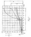
- the method according to the invention brings about a new characteristic of a device for extracting the impact energy, which enables the device to be used under different working conditions.
- the new characteristic curves of the device show a large increase in the stroke distance compared to the impact force.
- the slope of the stroke is significantly smaller for large values of external impact forces.
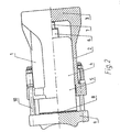
- An example of a device for carrying out the method for extracting the impact energy shown in FIG. 2 has a body 1 which consists of a sleeve 2 and a base 3. Inside the body, an elastomer shock absorber 4 is slidably disposed against the body.
- the piston rod 6, which has a large diameter, projects outward from the working cylinder 5 of the elastomer shock absorber.
- piston rod 6 another piston rod 7 with a small diameter is arranged such that it can be pushed into one another.
- the piston rod with the small diameter 7 lies against the bottom of the body and the bottom 8 of the elastomer shock absorber lies against the inside of a push plate 9.
- the cleat is connected to the body by means of connectors 10.
- the device according to the invention with an outer, elongated and increasing force is loaded - after overcoming the original Internal stress of the device - its length, due to the insertion of the Piston rod 7 in the working cylinder 5, reduced. Will be the end of their stroke reached, the external force outweighs the additional internal stress of the device and then the device is further reduced in length.
- the Length reduction is due to the insertion of the piston rod 6 with the larger one Causes diameter in the working cylinder 5, and it lasts until the piston rod 6 has reached the end of its stroke.
Landscapes
- Engineering & Computer Science (AREA)
- General Engineering & Computer Science (AREA)
- Mechanical Engineering (AREA)
- Health & Medical Sciences (AREA)
- Child & Adolescent Psychology (AREA)
- Vibration Dampers (AREA)
- Fluid-Damping Devices (AREA)
Applications Claiming Priority (3)
| Application Number | Priority Date | Filing Date | Title |
|---|---|---|---|
| PL97319799A PL183102B1 (pl) | 1997-04-30 | 1997-04-30 | Sposób pochłaniania energii zderzeń i aparat pochłaniający energię zderzeń, zwłaszcza w kolejowych sprzęgach automatycznych |
| PL31979997 | 1997-04-30 | ||
| PCT/PL1998/000020 WO1998049042A1 (de) | 1997-04-30 | 1998-04-30 | Verfahren und vorrichtung zur entziehung von stossenergie insbesondere in selbsttätigen kupplungen von schienenfahrzeugen |
Publications (2)
| Publication Number | Publication Date |
|---|---|
| EP0929433A1 EP0929433A1 (de) | 1999-07-21 |
| EP0929433B1 true EP0929433B1 (de) | 2003-08-06 |
Family
ID=20069796
Family Applications (1)
| Application Number | Title | Priority Date | Filing Date |
|---|---|---|---|
| EP98917820A Expired - Lifetime EP0929433B1 (de) | 1997-04-30 | 1998-04-30 | Verfahren und vorrichtung zur entziehung von stossenergie insbesondere in selbsttätigen kupplungen von schienenfahrzeugen |
Country Status (9)
| Country | Link |
|---|---|
| EP (1) | EP0929433B1 (pl) |
| CZ (1) | CZ291786B6 (pl) |
| DE (1) | DE59809201D1 (pl) |
| ES (1) | ES2203942T3 (pl) |
| PL (1) | PL183102B1 (pl) |
| RU (1) | RU2210514C2 (pl) |
| SK (1) | SK285696B6 (pl) |
| UA (1) | UA49919C2 (pl) |
| WO (1) | WO1998049042A1 (pl) |
Families Citing this family (2)
| Publication number | Priority date | Publication date | Assignee | Title |
|---|---|---|---|---|
| CN101612946B (zh) * | 2008-12-12 | 2011-05-18 | 青岛四方车辆研究所有限公司 | 双向式弹性胶泥缓冲器 |
| CZ2009214A3 (cs) | 2009-04-07 | 2010-06-23 | Protechnik S.R.O. | Automatické manipulacní zarízení |
Family Cites Families (9)
| Publication number | Priority date | Publication date | Assignee | Title |
|---|---|---|---|---|
| FR1363297A (fr) * | 1963-04-29 | 1964-06-12 | Domange Ets | Perfectionnements aux butées à grande capacité d'énergie |
| US3752462A (en) * | 1971-05-14 | 1973-08-14 | Clevite Corp | Elastomeric spring and frictional damping shock absorber |
| DE2722542A1 (de) * | 1977-05-18 | 1978-11-23 | Carl Ullrich Dr Peddinghaus | Feder mit stossdaempfung |
| DE8608541U1 (de) * | 1986-03-27 | 1987-08-27 | Ringfeder Gmbh, 4150 Krefeld | Hülsenpuffer zur federnden Aufnahme von Stoßkräften, insbesondere für Schienenfahrzeuge |
| US4960215A (en) * | 1988-12-22 | 1990-10-02 | Miner Enterprises, Inc. | Friction elastomer draft gear |
| US4998997A (en) * | 1989-02-15 | 1991-03-12 | Miner Enterprises, Inc. | Side bearing unit for railroad car |
| DE3914790A1 (de) * | 1989-05-05 | 1990-11-08 | Bergische Stahlindustrie | Zug- und stossvorrichtung fuer mittelpufferkupplungen von schienenfahrzeugen |
| PL172461B1 (pl) * | 1993-08-16 | 1997-09-30 | Urzadzen Mechanicznych Kamax S | Urzadzenie zderzne PL |
| DE19616944B4 (de) * | 1996-04-27 | 2006-05-18 | Suspa Holding Gmbh | Aufpralldämpfer |
-
1997
- 1997-04-30 PL PL97319799A patent/PL183102B1/pl not_active IP Right Cessation
-
1998
- 1998-04-30 ES ES98917820T patent/ES2203942T3/es not_active Expired - Lifetime
- 1998-04-30 UA UA99042143A patent/UA49919C2/uk unknown
- 1998-04-30 DE DE59809201T patent/DE59809201D1/de not_active Expired - Fee Related
- 1998-04-30 SK SK408-99A patent/SK285696B6/sk unknown
- 1998-04-30 CZ CZ19991036A patent/CZ291786B6/cs not_active IP Right Cessation
- 1998-04-30 EP EP98917820A patent/EP0929433B1/de not_active Expired - Lifetime
- 1998-04-30 RU RU99111475/28A patent/RU2210514C2/ru not_active IP Right Cessation
- 1998-04-30 WO PCT/PL1998/000020 patent/WO1998049042A1/de not_active Ceased
Also Published As
| Publication number | Publication date |
|---|---|
| CZ103699A3 (cs) | 1999-12-15 |
| ES2203942T3 (es) | 2004-04-16 |
| CZ291786B6 (cs) | 2003-05-14 |
| WO1998049042A1 (de) | 1998-11-05 |
| SK40899A3 (en) | 2000-02-14 |
| EP0929433A1 (de) | 1999-07-21 |
| DE59809201D1 (de) | 2003-09-11 |
| PL319799A1 (en) | 1998-11-09 |
| RU2210514C2 (ru) | 2003-08-20 |
| UA49919C2 (uk) | 2002-10-15 |
| SK285696B6 (sk) | 2007-06-07 |
| PL183102B1 (pl) | 2002-05-31 |
Similar Documents
| Publication | Publication Date | Title |
|---|---|---|
| DE2655705C3 (de) | Hydraulischer Teleskopschwingungsdampfer mit hydraulischem und elastischem Zuganschlag, insbesondere fur Kraftfahrzeuge | |
| DE3419364A1 (de) | Stufenlos blockierbares hubaggregat | |
| DE2123248A1 (de) | Axialaufhangesystem | |
| DE69914862T2 (de) | Dämpferventil für hydraulische Servolenkung | |
| DE2827513C2 (de) | In der Dämpfkraft einstellbares Ventil in einem Fluidstoßdämpfer | |
| DE2148860A1 (de) | Reibungs-Zugkupplung,insbesondere fuer Eisenbahnwagen | |
| DE718514C (de) | Seitenpuffer mit Stossfedern | |
| EP0929433B1 (de) | Verfahren und vorrichtung zur entziehung von stossenergie insbesondere in selbsttätigen kupplungen von schienenfahrzeugen | |
| DE2232963A1 (de) | Energieabsorptionsvorrichtung | |
| DE7036033U (de) | Energie absorbierender stossdaempfer, insbesondere hydraulischer puffer fuer schienenfahrzeuge. | |
| DE3126654A1 (de) | Hydraulischer teleskop-stossdaempfer, insbesondere fuer kraftfahrzeuge | |
| EP1469226A2 (de) | Längenverstellbare Gasfeder | |
| DE2642932B2 (de) | Abdichtung der Kolbenstange einer Feder- und Dämpfungsvorrichtung | |
| DE1809135B2 (de) | Zug- und Stoßvorrichtung für eine Mittelpufferkupplung an Schienenfahrzeugen | |
| EP0618094A1 (de) | Anhängerkupplung | |
| DE3035891C2 (de) | Vorrichtung zum Feststellen von um vorzugsweise horizontale Achsen schwenkbar gelagerten Bauteilen | |
| DE3039295C2 (de) | Radzylinder für eine hydraulisch betätigbare Trommelbremse eines Kraftfahrzeuges | |
| DE2118655C2 (de) | Zug- und Stoßvorrichtung für Mittelpufferkupplungen von Schienenfahrzeugen | |
| DE2434053A1 (de) | Stossdaempfer | |
| DE1921972A1 (de) | Elastische Kupplung | |
| DE3242830A1 (de) | Federnde vorderradaufhaengung fuer motorraeder | |
| DE3304888C1 (de) | Wellenkupplung | |
| DE3001169A1 (de) | Stossdaempfer-zylinderanordnung | |
| DE2742700A1 (de) | Federbein fuer radaufhaengungen an motorraedern | |
| DE586705C (de) | Reibungsstossdaempfer |
Legal Events
| Date | Code | Title | Description |
|---|---|---|---|
| PUAI | Public reference made under article 153(3) epc to a published international application that has entered the european phase |
Free format text: ORIGINAL CODE: 0009012 |
|
| 17P | Request for examination filed |
Effective date: 19990324 |
|
| AK | Designated contracting states |
Kind code of ref document: A1 Designated state(s): DE ES FI FR |
|
| RBV | Designated contracting states (corrected) |
Designated state(s): DE ES FI FR |
|
| GRAH | Despatch of communication of intention to grant a patent |
Free format text: ORIGINAL CODE: EPIDOS IGRA |
|
| RIN1 | Information on inventor provided before grant (corrected) |
Inventor name: ULIANOW, OLEG ALEKSANDROWICZ Inventor name: CURIENKO, WLADIMIR NIKOLAJEWICZ Inventor name: SKURATOW, ALEKSANDER JEWGIENIEWICZ Inventor name: DIMITROW, WALENTIN WIKTOROWICZ Inventor name: FILIPOW, WIKTOR NIKOLAJEWICZ Inventor name: MICHAKOW, WLADIMIR MAKSYMOWICZ Inventor name: MILCZARSKI, KAZIMIERZ Inventor name: POPLAWSKI, WOJCIECH Inventor name: KEDZIOR, JOZEF Inventor name: CHMIELEWSKI, ANDRZEJ Inventor name: STRZYZ, EUGENIUSZ Inventor name: KUBICKI, ANTONI |
|
| GRAH | Despatch of communication of intention to grant a patent |
Free format text: ORIGINAL CODE: EPIDOS IGRA |
|
| GRAA | (expected) grant |
Free format text: ORIGINAL CODE: 0009210 |
|
| AK | Designated contracting states |
Designated state(s): DE ES FI FR |
|
| REF | Corresponds to: |
Ref document number: 59809201 Country of ref document: DE Date of ref document: 20030911 Kind code of ref document: P |
|
| REG | Reference to a national code |
Ref country code: ES Ref legal event code: FG2A Ref document number: 2203942 Country of ref document: ES Kind code of ref document: T3 |
|
| ET | Fr: translation filed | ||
| PLBE | No opposition filed within time limit |
Free format text: ORIGINAL CODE: 0009261 |
|
| STAA | Information on the status of an ep patent application or granted ep patent |
Free format text: STATUS: NO OPPOSITION FILED WITHIN TIME LIMIT |
|
| 26N | No opposition filed |
Effective date: 20040507 |
|
| PGFP | Annual fee paid to national office [announced via postgrant information from national office to epo] |
Ref country code: ES Payment date: 20070425 Year of fee payment: 10 |
|
| PGFP | Annual fee paid to national office [announced via postgrant information from national office to epo] |
Ref country code: FI Payment date: 20070430 Year of fee payment: 10 |
|
| PGFP | Annual fee paid to national office [announced via postgrant information from national office to epo] |
Ref country code: DE Payment date: 20070530 Year of fee payment: 10 |
|
| PGFP | Annual fee paid to national office [announced via postgrant information from national office to epo] |
Ref country code: FR Payment date: 20070420 Year of fee payment: 10 |
|
| PG25 | Lapsed in a contracting state [announced via postgrant information from national office to epo] |
Ref country code: DE Free format text: LAPSE BECAUSE OF NON-PAYMENT OF DUE FEES Effective date: 20081101 |
|
| REG | Reference to a national code |
Ref country code: FR Ref legal event code: ST Effective date: 20081231 |
|
| PG25 | Lapsed in a contracting state [announced via postgrant information from national office to epo] |
Ref country code: FI Free format text: LAPSE BECAUSE OF NON-PAYMENT OF DUE FEES Effective date: 20080430 |
|
| PG25 | Lapsed in a contracting state [announced via postgrant information from national office to epo] |
Ref country code: FR Free format text: LAPSE BECAUSE OF NON-PAYMENT OF DUE FEES Effective date: 20080430 |
|
| REG | Reference to a national code |
Ref country code: ES Ref legal event code: FD2A Effective date: 20080503 |
|
| PG25 | Lapsed in a contracting state [announced via postgrant information from national office to epo] |
Ref country code: ES Free format text: LAPSE BECAUSE OF NON-PAYMENT OF DUE FEES Effective date: 20080503 |