EP0929145A2 - Field oriented control for the drive of a pressing machine - Google Patents
Field oriented control for the drive of a pressing machine Download PDFInfo
- Publication number
- EP0929145A2 EP0929145A2 EP99300247A EP99300247A EP0929145A2 EP 0929145 A2 EP0929145 A2 EP 0929145A2 EP 99300247 A EP99300247 A EP 99300247A EP 99300247 A EP99300247 A EP 99300247A EP 0929145 A2 EP0929145 A2 EP 0929145A2
- Authority
- EP
- European Patent Office
- Prior art keywords
- phase
- current
- servomotor
- command
- pressing machine
- Prior art date
- Legal status (The legal status is an assumption and is not a legal conclusion. Google has not performed a legal analysis and makes no representation as to the accuracy of the status listed.)
- Withdrawn
Links
Images


Classifications
-
- B—PERFORMING OPERATIONS; TRANSPORTING
- B30—PRESSES
- B30B—PRESSES IN GENERAL
- B30B15/00—Details of, or accessories for, presses; Auxiliary measures in connection with pressing
- B30B15/14—Control arrangements for mechanically-driven presses
- B30B15/148—Electrical control arrangements
-
- H—ELECTRICITY
- H02—GENERATION; CONVERSION OR DISTRIBUTION OF ELECTRIC POWER
- H02P—CONTROL OR REGULATION OF ELECTRIC MOTORS, ELECTRIC GENERATORS OR DYNAMO-ELECTRIC CONVERTERS; CONTROLLING TRANSFORMERS, REACTORS OR CHOKE COILS
- H02P21/00—Arrangements or methods for the control of electric machines by vector control, e.g. by control of field orientation
- H02P21/22—Current control, e.g. using a current control loop
Definitions
- the present invention relates to a pressing machine having a press shaft driven by means of an AC servomotor.
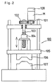
- a pressing machine 100 is an apparatus in which a plate material is interposed between a top die 106 and a bottom die 107, and is pressed to be shaped between the two dies. Pressing force is supplied by means of a servomotor M. The rotation of the servomotor M is transmitted to a ball screw 103 by means of a transmission mechanism including gears 101 and 102, etc. The ball screw 103 is engagedly fitted with a nut 104 that has a ram 104 at the other end. When the ball screw 103 rotates, the nut 104 and the ram 105 move in the axial direction, thereby changing the distance between the top and bottom forces 106 and 107.
- the respective positions of the forces can be detected by means of a position detector 108 that is attached to the servomotor M.
- each mechanical portion is subjected to position control.
- position and speed detectors are attached to the AC servomotor.
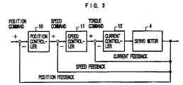
- position loop control is carried out to obtain a speed command in accordance with a position command and a position feedback signal by means of a position control section 10
- speed loop control is carried out to obtain a torque command in accordance with the speed command and a speed feedback signal by means of a speed control section 11.
- current loop control is carried out for each of three phases in response to the torque command by means of a current control section 12, whereby a voltage command corresponding to current to be supplied is obtained.
- the AC servomotor is driven by means of a power amplifier such as an inverter.
- speed loop control may be performed without effecting position control.
- FIG. 4 is a block diagram showing a conventional current control system for the AC servomotor. Based on a torque command delivered from a speed loop and a rotor phase ⁇ from a rotor phase detector attached to the AC servomotor, a U-phase current command is obtained by multiplying the torque command by sin ⁇ in the U-phase (rotor phase is based on the U-phase), a V-phase current command is obtained by multiplying the torque command by sin( ⁇ + 2 ⁇ /3) with a phase difference of 120° in the V-phase, and a W-phase current command is obtained by multiplying the torque command by sin( ⁇ - 2 ⁇ /3) with an additional phase difference of 120° in the W-phase.
- current loop control based on integral-plus-proportional control is effected to obtain a voltage command (PWM command) in accordance with the current command and a current feedback signal for each phase, and the servomotor is driven by means of an servo amplifier such as an inverter.
- PWM command a voltage command
- k1, k2, R and L in each current loop are an integral gain, proportional gain, winding resistance of the servomotor, and inductance of the servomotor, respectively.
- s in each current loop is a differential operator.
- the frequency of AC current (frequency of AC current generated in the inverter) increases as the rotational speed of the servomotor increases.
- the gain may be lowered, or a phase lag may be caused.
- the power factor is lowered, entailing increased driving current, lowered maximum torque, etc.
- an AC servomotor is used for its press shaft.
- pressing operation is carried out continuously and repeatedly.
- the AC servomotor for driving each moving element of the pressing machine must be driven at high speed. If the high-speed operation is carried out, however, the driving current increases, as described above, so that heat release from the motor increases, thus constituting a hindrance to the speed-up of the pressing operation. Further, the speed-up of the pressing operation requires generation of high torque. Since the maximum torque is lowered, as mentioned before, however, high torque cannot be generated without problem.
- the object of the present invention is to provide a pressing machine capable of high-speed pressing operation.
- a pressing machine having elements driven by means of an AC servomotor, wherein a control section of said AC servomotor has a d-q conversion function for conversion from a three-phase mode into a two-phase mode composed of a d-phase in the direction of a magnetic flux formed by a magnetic field system and a q-phase perpendicular to the d-phase, the d-q conversion function serving for the current control of the AC servomotor.
- three-phase-to two-phase conversion is effected with use of the driving current and rotor phase of the AC servomotor for driving the moving elements of the pressing machine, whereupon a d-phase current in the direction of a magnetic flux formed by a magnetic field system and a q-phase current perpendicular to the d-phase current are obtained and used as feedback currents.
- Current feedback control is carried out with a q-phase current command used as a torque command and with a d-phase current command adjusted to zero, whereupon d-and q-phase command voltages are obtained.
- Two-phase-to-three-phase conversion is effected to obtain commands for the individual phases of the AC servomotor with use of the d- and q-phase command voltages, and the AC servomotor is drivingly controlled.
- phase lead control is effected to advance the phase of the q-phase current, thereby preventing reduction of the output torque of the AC servomotor and ensuring high-speed, high-torque drive of the servomotor.
- the AC servomotor can be driven at high speed and with high torque and small driving current, so that heat release from the servomotor can be reduced to facilitate high-speed pressing operation.
- the production efficiency can be improved. Since the heat release is reduced, the capacity of cooling equipment for the motor can be also reduced.
- pressing a thick plate which requires high-speed, high-torque operation, can be carried out without hindrance. Since a force substantially equal to the existing pressing force of the pressing machine can be generated even in a low motor speed zone, moreover, the level of noises from pressing shock can be lowered.
- d-q conversion between a three-phase mode and a two-phase mode is used as a method for preventing increase of driving current attributable to reduction in power factor and also preventing lowering of the maximum torque, in current control for an AC servomotor.
- a d-axis is set in the direction of a magnetic flux that is generated by a magnetic field
- a q-axis is set at right angles to the d-axis
- a current Id and voltage Vd in the d-axis direction and a current Iq and voltage Vq in the q-axis direction are obtained and controlled.
- FIG. 1 is a block diagram of a current control section according to one embodiment of the present invention for current control based on the d-q conversion.
- a current control section for an AC servomotor for driving moving elements of a pressing machine can be composed of the current control section shown in the block diagram of FIG. 1.
- the current control section shown in FIG. 1 is used in place of a current control section 12 and a servomotor 4 shown in the block diagram of FIG. 3.
- numeral 3 denotes a power amplifier composed of an inverter or the like; 4, any one of AC servomotors; 5, a rotor phase detector for detecting the rotor phase ⁇ r of the AC servomotor 4; 6, magnetism saturation correcting means for correcting the rotor phase when magnetism saturation is caused in the AC servomotor 4; and 7, a three-phase-to-two-phase converter for converting three-phase or U-, V-, and W-phase currents Iu, Iv and Iw into two-phase or d- and q-phase currents Id and Iq.
- the three-phase-to-two-phase converter 7 carries out the operation of the following expression (2) to obtain the d- and q- phase currents Id and Iq in accordance with any two-phase currents (Iu and Iv in FIG. 1), out of U-, V-, and W-phase actual currents of the AC servomotor 4 detected by means of a current detector (not shown) and the corrected rotor phase ⁇ obtained by wadding the correction value ⁇ m to the detected rotor phase ⁇ r:
- the U-, V-, and W-phase command voltages Vu, Vv and Vw are obtained from the resulting d- and q-phase command voltages Vd and Vq by means of the two-phase-to-three-phase converter 2.
- These command voltages are delivered to the power amplifier 3 so that the currents Iu, Iv and Iw are supplied to the individual phases of the AC servomotor 4 by means of an inverter or the like, thus drivingly controlling the servomotor 4.
- a d-phase actual current is controlled to be equal to the command value "0" without any phase lag in a current loop, so that there is only a q-phase active current.
- the driving current supplied to the AC servomotor decreases, and heat release from the motor is reduced, so that the level of the load that causes overheat can be lowered. Accordingly, the drive cycle of the pressing machine can be increased in speed.
- the rotor phase ⁇ r is subjected to the magnetic saturation correction ⁇ m by means of the magnetism saturation correcting means 6 (see FIG. 1) during high-speed rotation that entails magnetic saturation, whereby the phase of the q-phase current Iq is advanced to prevent the torque from lowering during the high-speed rotation.
- the magnetism saturation correcting means 6 see FIG. 1
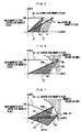
- FIGS. 5, 6 and 7 are views showing magnetic flux vectors on the d-q coordinates of the AC servomotor, in which the d-axis represents the direction of the magnetic flux (main magnetic flux ⁇ M) of a permanent magnet of a rotor, and the q-axis represents the direction of a magnetic flux M ⁇ Iq that is generated by the active current Iq.
- the d- and q-axes cross each other at right angles.
- a resultant magnetic flux that is obtained by adding, in terms of vector, the main magnetic flux ⁇ M of the permanent magnet of the rotor and the magnetic flux M ⁇ Iq occurring based on the active current Iq is an active magnetic flux ⁇ g for torque formation.
- the active magnetic flux ⁇ g increases so that magnetic saturation occurs in the magnetic circuit in the motor.
- the active magnetic flux ⁇ g enters a magnetic saturation zone, however, it never increases even if the q-phase current Iq is increased, so that the torque ceases to increase.
- Magnetic saturation correction is carried out to cope with this torque reduction. As described below, this magnetic saturation correction is characterized by advancing the phase of the q-phase current Iq to prevent the magnetic flux ⁇ g from entering the magnetic saturation zone.
- phase of the q-phase current Iq1 is advanced for a certain angle ⁇ when the magnetic flux ⁇ gs formed by the q-phase current Ig1 in the q-axis direction is at the boundary of the magnetic saturation zone, as shown in the magnetic flux vector diagram of FIG. 6, the phase of the magnetic flux ⁇ gs advances by the angle ⁇ at the same time. Thereupon, the magnetic flux ⁇ g, advanced by the angle ⁇ in phase, moves a certain distance away from the boundary of the magnetic saturation zone. Accordingly, the q-phase current Iq1 can be further increased so that the magnetic flux ⁇ gs in this state reaches the boundary of the magnetic saturation zone.
- Control of the phase lead of the q-phase current can be carried out actually by advancing the rotor phase detected by means of the rotor phase detector, thereby advancing d-q coordinates for control ahead of actual d-q coordinates.
- the mode of control of the control system is a conventional one.
- the control of the phase lead of the q-phase current is carried out on the d-q coordinates for control, the phase of which is advanced by ⁇ m ahead of the actual d-q coordinates.
- Magnetic saturation correction can be effected by supplying the q-phase current in the direction of the q-axis of the d-q coordinates for control.
- the control system performs control in a conventional manner.
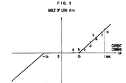
- phase lead angle ⁇ m for the magnetic saturation correction according to the present invention.
- the graph of FIG. 9 indicates that the lead angle ⁇ m is obtained from the current command Iq*.
- Iq* is a q-phase command current
- Ib a current value for assigning the value of the current command which starts to enter the magnetic saturation zone starts to be entered
- k a proportional constant
- abs absolute value
- sign a sign.
- the proportional constant k is a magnetic saturation coefficient, which depends on the varied magnetic saturation characteristics for each motor and can be settled experimentally.
- magnetic saturation correction need not be effected in the case where the level of the current command Iq* is so low that the generated magnetic flux is off the magnetic saturation zone. Accordingly, motor control is carried out with the lead angle ⁇ m at 0° without subjecting the current command Iq* to phase controL In the case where the current command Iq* exceeds the set value Ib so that the generated magnetic flux falls within the magnetic saturation zone, on the other hand, magnetic saturation correction is carried out using expression (4). More specifically, ⁇ m corresponding to the current command Iq* is obtained according to expression (4), and control is carried out on the d-q coordinates for control, the phase of which is advanced by ⁇ m ahead of the actual d-q coordinates.
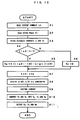
- FIG. 10 there is shown processing a processor of a digital servo circuit for controlling each servomotor in a control device for controlling the pressing machine executes with every current loop processing period. Since the pressing machine and the digital servo circuit are constructed in the same manner as conventional ones, a description of their arrangements is omitted therein.
- the processor of the digital servo circuit carries out conventional position loop processing and speed loop processing (by the position control section 10 and the speed control section 11 of FIG. 3) in response to a position command (or speed command), thereby obtaining the current command (torque command) Iq*.
- the processor reads the current command Iq* (Step S1), and fetches the rotor phase ⁇ r and u- and v-phase current feedback values Iu and Iv from the rotor phase detector (Steps S2 and S3).
- the processor determines whether or not the current value Ib, which is set for magnetic saturation, is exceeded by the absolute value of the read current command Iq* (Step S4). If the set value Ib is not exceeded, the phase correction value ⁇ m is set at "0" (Step S6). If the set value Ib is exceeded, the operation of expression (4) is carried out to obtain the phase correction value ⁇ m (Step S6 and Step S5). Substantially, the corrected rotor phase. ⁇ is obtained by adding the phase correction value ⁇ m to the rotor phase ⁇ r read in Step S2 (Step S7).
- Step S3 Based on the corrected rotor phase ⁇ and the u- and v-phase current feedback values Iu and Iv fetched in Step S3, the operation of expression (2) is carried out to obtain the two-phase currents Id and Iq from the three-phase currents Iu, Iv and Iw (Step S8).
- Conventional current loop processing is carried out to obtain the d-phase command voltage Vd with the obtained d-phase current Id used as a feedback current and with the d-phase current command set at "0".
- D-q conversion is effected according to expression (1), based on the d- and q-phase command voltages Vd and Vq thus obtained and the rotor phase ⁇ advanced by the correction in Step S7.
- the three-phase voltages Vu, Vv and Vw are obtained from two-phase voltages Vd and Vq and are delivered as voltage commands (PWM commands) to the power amplifier 6 (Steps S10 and S11).
- the power amplifier performs PWM control by means of an inverter, and supplies the currents Iu, Iv and Iw for the individual phases to the AC servomotor 4 to drive the same.
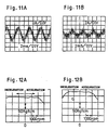
- FIG. 11A shows the result of measurement of current that flows through an AC servomotor for driving moving elements of a pressing machine in the case where the conventional current control for three individual phases is applied to the AC servomotor.
- FIG. 11B shows the result of measurement of current that flows through the AC servomotor for driving the moving elements of the pressing machine in the case where the aforementioned current control system based on d-q conversion is applied to the AC servomotor.
- each section of the axis of abscissa represents 2 milliseconds
- each section of the axis of ordinate represents two amperes.
- the current value is lowered by a margin for the reduction of reactive current (d-phase current) in the case where the current control system based on d-q conversion is applied to the AC servomotor.
- FIG. 12A shows the maximum torque generated by the AC servomotor for driving the moving elements of the pressing machine in the case where the conventional current control for three individual phases is applied to the AC servomotor.
- FIG. 11B shows the maximum torque generated by the AC servomotor for driving the moving elements of the pressing machine in the case where the aforementioned current control system based on d-q conversion is applied to the AC servomotor.
- the maximum torque obtained with use of the current control system based on d-q conversion is about 20% to 30% higher than the maximum torque obtained with use of the conventional current control system (FIG. 12A). According to the current control system of the invention, high torque can be generated even in the high-speed rotation zone.
Landscapes
- Engineering & Computer Science (AREA)
- Mechanical Engineering (AREA)
- Power Engineering (AREA)
- Control Of Ac Motors In General (AREA)
- Control Of Presses (AREA)
- Control Of Position Or Direction (AREA)
Applications Claiming Priority (2)
| Application Number | Priority Date | Filing Date | Title |
|---|---|---|---|
| JP1643898 | 1998-01-13 | ||
| JP10016438A JPH11197897A (ja) | 1998-01-13 | 1998-01-13 | プレス機械 |
Publications (1)
| Publication Number | Publication Date |
|---|---|
| EP0929145A2 true EP0929145A2 (en) | 1999-07-14 |
Family
ID=11916246
Family Applications (1)
| Application Number | Title | Priority Date | Filing Date |
|---|---|---|---|
| EP99300247A Withdrawn EP0929145A2 (en) | 1998-01-13 | 1999-01-13 | Field oriented control for the drive of a pressing machine |
Country Status (2)
| Country | Link |
|---|---|
| EP (1) | EP0929145A2 (ja) |
| JP (1) | JPH11197897A (ja) |
Cited By (1)
| Publication number | Priority date | Publication date | Assignee | Title |
|---|---|---|---|---|
| CN102019714A (zh) * | 2009-09-17 | 2011-04-20 | 会田工程技术有限公司 | 压力机和控制方法 |
Families Citing this family (4)
| Publication number | Priority date | Publication date | Assignee | Title |
|---|---|---|---|---|
| JP4764124B2 (ja) * | 2004-12-17 | 2011-08-31 | 三菱重工業株式会社 | 永久磁石型同期モータの制御装置及びその方法 |
| JP5444028B2 (ja) * | 2010-02-03 | 2014-03-19 | 本田技研工業株式会社 | 電動パワーステアリング装置 |
| JP5780022B2 (ja) * | 2011-07-05 | 2015-09-16 | トヨタ自動車株式会社 | 交流電動機の制御装置および制御方法 |
| JP7286528B2 (ja) * | 2019-12-13 | 2023-06-05 | 株式会社日立産機システム | 電力変換装置 |
-
1998
- 1998-01-13 JP JP10016438A patent/JPH11197897A/ja active Pending
-
1999
- 1999-01-13 EP EP99300247A patent/EP0929145A2/en not_active Withdrawn
Cited By (4)
| Publication number | Priority date | Publication date | Assignee | Title |
|---|---|---|---|---|
| CN102019714A (zh) * | 2009-09-17 | 2011-04-20 | 会田工程技术有限公司 | 压力机和控制方法 |
| EP2311630A3 (en) * | 2009-09-17 | 2012-03-14 | Aida Engineering, Ltd. | Press machine and method of controlling the same |
| CN102019714B (zh) * | 2009-09-17 | 2014-11-12 | 会田工程技术有限公司 | 压力机和控制方法 |
| US9021946B2 (en) | 2009-09-17 | 2015-05-05 | Aida Engineering, Ltd. | Press machine and method of controlling the same |
Also Published As
| Publication number | Publication date |
|---|---|
| JPH11197897A (ja) | 1999-07-27 |
Similar Documents
| Publication | Publication Date | Title |
|---|---|---|
| EP0836270B1 (en) | Method for controlling current of ac servo motor | |
| EP1276225B1 (en) | Motor control apparatus for reducing higher harmonic current | |
| EP0911959B1 (en) | Injection molding machine | |
| US6809492B2 (en) | Speed control device for AC electric motor | |
| US6407531B1 (en) | Method and system for controlling a synchronous machine over full operating range | |
| US7235947B2 (en) | Synchronous motor control method and synchronous motor control system | |
| EP1787385B1 (en) | Method for controlling a wound rotor synchronous motor | |
| US9136789B2 (en) | Synchronous motor control apparatus | |
| EP1562283A1 (en) | Servomotor control device for robot and robot having the device | |
| CA1299642C (en) | Universal field-oriented controller | |
| US8350517B2 (en) | Applying a control unit to an asynchronous machine which is operated without a rotary encoder | |
| EP0793338B1 (en) | Method for controlling current of servomotor | |
| EP3128668B1 (en) | Electric apparatus drive device | |
| US5955863A (en) | Electric current control method for a servomotor | |
| EP0929145A2 (en) | Field oriented control for the drive of a pressing machine | |
| JP3383682B2 (ja) | Acサーボモータの電流制御方法 | |
| EP0503879B1 (en) | Synchronous motor with permanent magnets and motor system | |
| JP3468123B2 (ja) | サーボモータ制御装置 | |
| JP3751991B2 (ja) | Acサーボモータの電流制御方法 | |
| JPH0614592A (ja) | Acサーボモータの加速度制御方式 | |
| JPH11178399A (ja) | 永久磁石式同期モータの制御方法 | |
| JP2002325498A (ja) | 交流電動機の制御装置 | |
| Hassan | Improving the power efficiency of a rotor flux-oriented induction motor drive |
Legal Events
| Date | Code | Title | Description |
|---|---|---|---|
| PUAI | Public reference made under article 153(3) epc to a published international application that has entered the european phase |
Free format text: ORIGINAL CODE: 0009012 |
|
| AK | Designated contracting states |
Kind code of ref document: A2 Designated state(s): AT BE CH CY DE DK ES FI FR GB GR IE IT LI LU MC NL PT SE |
|
| AX | Request for extension of the european patent |
Free format text: AL;LT;LV;MK;RO;SI |
|
| STAA | Information on the status of an ep patent application or granted ep patent |
Free format text: STATUS: THE APPLICATION HAS BEEN WITHDRAWN |
|
| 18W | Application withdrawn |
Withdrawal date: 20000713 |