EP0928651A1 - Verfahren zur Herstellung von Bauteilen, vorzugsweise Prototypen - Google Patents
Verfahren zur Herstellung von Bauteilen, vorzugsweise Prototypen Download PDFInfo
- Publication number
- EP0928651A1 EP0928651A1 EP99100065A EP99100065A EP0928651A1 EP 0928651 A1 EP0928651 A1 EP 0928651A1 EP 99100065 A EP99100065 A EP 99100065A EP 99100065 A EP99100065 A EP 99100065A EP 0928651 A1 EP0928651 A1 EP 0928651A1
- Authority
- EP
- European Patent Office
- Prior art keywords
- model
- molding compound
- production
- components
- prototype according
- Prior art date
- Legal status (The legal status is an assumption and is not a legal conclusion. Google has not performed a legal analysis and makes no representation as to the accuracy of the status listed.)
- Withdrawn
Links
- 238000000034 method Methods 0.000 title claims abstract description 50
- 238000004519 manufacturing process Methods 0.000 claims abstract description 25
- 238000005266 casting Methods 0.000 claims abstract description 7
- 229910052602 gypsum Inorganic materials 0.000 claims description 39
- 239000010440 gypsum Substances 0.000 claims description 39
- 150000001875 compounds Chemical class 0.000 claims description 35
- 238000000465 moulding Methods 0.000 claims description 35
- 229910052751 metal Inorganic materials 0.000 claims description 5
- 239000002184 metal Substances 0.000 claims description 5
- 229910000831 Steel Inorganic materials 0.000 claims description 4
- 239000010959 steel Substances 0.000 claims description 4
- 230000002787 reinforcement Effects 0.000 claims description 3
- 229910052782 aluminium Inorganic materials 0.000 claims description 2
- XAGFODPZIPBFFR-UHFFFAOYSA-N aluminium Chemical compound [Al] XAGFODPZIPBFFR-UHFFFAOYSA-N 0.000 claims description 2
- 239000012778 molding material Substances 0.000 claims 1
- 239000011505 plaster Substances 0.000 description 6
- 239000004793 Polystyrene Substances 0.000 description 4
- 229920002223 polystyrene Polymers 0.000 description 4
- 238000011161 development Methods 0.000 description 2
- 230000018109 developmental process Effects 0.000 description 2
- 238000005495 investment casting Methods 0.000 description 2
- QFLWZFQWSBQYPS-AWRAUJHKSA-N (3S)-3-[[(2S)-2-[[(2S)-2-[5-[(3aS,6aR)-2-oxo-1,3,3a,4,6,6a-hexahydrothieno[3,4-d]imidazol-4-yl]pentanoylamino]-3-methylbutanoyl]amino]-3-(4-hydroxyphenyl)propanoyl]amino]-4-[1-bis(4-chlorophenoxy)phosphorylbutylamino]-4-oxobutanoic acid Chemical compound CCCC(NC(=O)[C@H](CC(O)=O)NC(=O)[C@H](Cc1ccc(O)cc1)NC(=O)[C@@H](NC(=O)CCCCC1SC[C@@H]2NC(=O)N[C@H]12)C(C)C)P(=O)(Oc1ccc(Cl)cc1)Oc1ccc(Cl)cc1 QFLWZFQWSBQYPS-AWRAUJHKSA-N 0.000 description 1
- 230000001154 acute effect Effects 0.000 description 1
- 230000009286 beneficial effect Effects 0.000 description 1
- 239000000919 ceramic Substances 0.000 description 1
- 238000007598 dipping method Methods 0.000 description 1
- 230000009189 diving Effects 0.000 description 1
- 238000005516 engineering process Methods 0.000 description 1
- 239000007788 liquid Substances 0.000 description 1
- 238000010943 off-gassing Methods 0.000 description 1
- 239000004033 plastic Substances 0.000 description 1
- 230000003014 reinforcing effect Effects 0.000 description 1
Images


Classifications
-
- B—PERFORMING OPERATIONS; TRANSPORTING
- B28—WORKING CEMENT, CLAY, OR STONE
- B28B—SHAPING CLAY OR OTHER CERAMIC COMPOSITIONS; SHAPING SLAG; SHAPING MIXTURES CONTAINING CEMENTITIOUS MATERIAL, e.g. PLASTER
- B28B7/00—Moulds; Cores; Mandrels
- B28B7/34—Moulds, cores, or mandrels of special material, e.g. destructible materials
- B28B7/346—Manufacture of moulds
-
- B—PERFORMING OPERATIONS; TRANSPORTING
- B22—CASTING; POWDER METALLURGY
- B22C—FOUNDRY MOULDING
- B22C7/00—Patterns; Manufacture thereof so far as not provided for in other classes
Definitions
- the present invention relates to a method for producing components, preferably prototypes, in which a lost model (positive) of the component is produced in a first step, and then the model is cast using a molding compound to produce a mold (negative) and finally this mold is used to produce the component, preferably a prototype, in the casting process.
- Processes of the aforementioned type, which are preferably used for Production of complex prototypes are used, which are used for Example containing complex cavities are from the prior art Technology known.
- One such method is, for example Gypsum casting process, in which the said molding compound Is gypsum mass.
- Gypsum casting process instead of Gypsum casting process used the so-called investment casting process for the production of such prototypes. Both mentioned Procedure is common that they have the disadvantage that they for the production of prototypes with complex shapes and / or complex cavities either not at all or but require considerable effort.
- the object of the present invention is a Process for the production of components, in particular Prototypes of the type mentioned at the beginning are also available make that a less complex, quick and enables cheaper production of the component.
- a solution according to the invention provides this object Method of the type mentioned at the beginning with the characteristic features of the main claim.
- the procedure according to the invention is such that the Model in several successive steps with the Pouring molding compound and / or backfilling, the respective Placement of the model relative to a reference plane at each of these individual steps of pouring / filling.
- the main problem with previous procedures has been that in models with complex cavities, an image of the Cavities through the molding compound was not possible because the air from these cavities of the model when filling with the molding compound could not escape completely.
- the problem according to the invention is overcome.
- the first step is to cast the model the molding compound and fills the cavities as far as this is possible with the molding compound in a first arrangement of the Model relative to the reference plane. You may have to do this Close the side openings of the model so that the Molding compound cannot run out there. Filling the Molding compound is then made through openings from above. Then you change the arrangement of the model relative to that Reference plane, for example you rotate the model 90 ° by one of its axes.
- the model contains certain cavities, for example relatively long channels that are poured out with the molding compound then, according to a preferred further development of the method according to the invention may be advantageous if into the areas of the molding compound filling the channels Reinforcing to prevent removal after of the model (it is a lost model) the hardened parts of the molding compound, for example longer arms, if you pour out channels, break off or otherwise damage to take.
- Suitable elements can be used for such reinforcement use, for example wires or other metal parts Flat steel, round steel or the like.
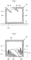
- FIG. 1 The illustration shows a model 10 which is used for the application of the method according to the invention for the production of a prototype and which, for example, consists of a sintered polystyrene.
- This model 10 is shown schematically in a highly simplified manner in the illustration according to FIG. 1 in order to explain the method by way of example.
- the cavity of the model 10 is filled with a molding compound, for example a gypsum compound 11.
- the models are generally of a significantly more complex structure with regard to their external shape and their cavities.
- the method according to the invention is carried out in the same manner as is explained below using the simplified model 10.
- the model 10 as shown in FIG. 1 consists of a bottom 10a, a vertical adjoining it on the left Sidewall 10b and a right adjoining it vertical side wall 10c.
- the model 10 also has one top wall 10d, which is only partially across the width of the Model extends and runs parallel to the floor 10a. From the left side wall 10b extends in a pointed manner Angle at the top towards the cavity inwards and an inclined partial wall 10e downwards. As well extends from the top wall 10d at its inner end out at an acute angle down and towards the right side wall 10c is an integrally formed inclined partial wall 10f.
- the gypsum mass 11a, 11b can then then again via the opening 13 from the run out both cavities 12a, 12b down. Of the main part of the cavity lying further up will still not filled with gypsum mass 11, but this is only done then in a second process step.
- model 10 which is usually made Plastic consists, for example, of sintered polystyrene, remove, for example by burning out or other methods and thus receives the plaster form, which is basically the negative for the Production of the prototype to be cast.
- the connecting part 15 is shown enlarged in FIG. 3.
- the connecting part 15 with its shaft 15a partially into the already set gypsum mass 11a embedded. However, a piece of the shaft 15a projects into the initially empty space as well as the Nut 16 to the screw.
- the head 15b has on his Underside undercut surfaces 15c. Based on these anchor-like shape of the screw head 15b with the undercut surfaces 15c and the shape of the nut 16 there is a good connection of the fresh gypsum mass 11 after filling in the hardened gypsum mass 11a.
- the Shape of the connecting parts 15 is in the embodiment 3 quite arbitrarily chosen, these can for Example also have heads with a dovetail shape or for example grooves, corrugation, teeth or similar.
- Fig. 5 first shows the schematic sectional view of a another model 20, which according to the inventive method is filled in several steps.
- the model 20 has several cavities, which are arranged so that the Do not completely fill the model in one process step leaves. It is therefore according to the invention that the Model 20 initially in the position shown in FIG the upper cavity shown there with a plaster mass 11a is filled. In this gypsum mass 11a can in turn Connection part 15 are introduced to the connection to another gypsum mass in a subsequent one Process step to improve.
- the lower cavity 12b So So, as can be seen in Fig. 5, remains initially unfilled.
- the model 20 is 180 ° in the Plane rotated so that it is shown in Fig.
- Outgoing 6 shows the model 20 at 90 ° in Turned counterclockwise in the drawing plane and then placed in a container 21, which is another gypsum mass 11c contains.
- this gypsum mass 11c can Example by burning out the model 20, see above that you then get a plaster mold that has cavities, which correspond to the shape of the previous model 20.
- these Gypsum mold is then again poured a metal and one then receives the component that has the same shape as the previous one Model 20 corresponds.
- the gypsum mass 11a, 11b, 11c can again be removed mechanically.
Landscapes
- Engineering & Computer Science (AREA)
- Mechanical Engineering (AREA)
- Manufacturing & Machinery (AREA)
- Chemical & Material Sciences (AREA)
- Ceramic Engineering (AREA)
- Producing Shaped Articles From Materials (AREA)
- Moulds For Moulding Plastics Or The Like (AREA)
Abstract
wobei man das Modell (10, 20) in mehreren aufeinanderfolgenden Schritten mit der Formmasse (11a, 11b, 11c) abgießt und/oder verfüllt und man die jeweilige Anordnung des Modells (10, 20) relativ zu einer Bezugsebene bei jedem dieser einzelnen Schritte des Abgießens/Verfüllens ändert.
Description
und anschließend das Modell mittels einer Formmasse zur Herstellung einer Form (Negativ) abgegossen wird und schließlich diese Form zur Herstellung des Bauteils, vorzugsweise Prototyps, im Gußverfahren dient.
- Fig. 1
- eine schematisch vereinfachte Schnittzeichnung eines Modells, das nach dem erfindungsgemäßen Verfahren mit einer Gipsmasse verfüllt wird;
- Fig. 2
- eine entsprechende schematisch vereinfachte Darstellung des Modells von Fig. 1 jedoch in einer um 90° im Uhrzeigersinn gedrehten Anordnung;
- Fig. 3
- eine vergrößerte Detailansicht eines Ausschnitts III aus Fig. 2, jedoch in einer anderen Anordnung;
- Fig. 4
- eine weitere schematisch vereinfachte Ansicht der fertigen Form entstanden aus dem Modell von Fig. 1.
- Fig. 5
- eine schematisch vereinfachte Schnittzeichnung eines Modells, das nach dem erfindungsgemäßen Verfahren verfüllt wird, gemäß einem weiteren Ausführungsbeispiel;
- Fig. 6
- eine weitere Ansicht des in Fig. 5 gezeigten Modells in einer um 180° gedrehten Anordnung;
- Fig. 7
- eine weitere Ansicht des Modells gemäß den Fig. 5 und 6 in einer weiteren Phase des erfindungsgemäßen Verfahrens.
Die Darstellung zeigt ein Modell 10, das für die Anwendung des erfindungsgemäßen Verfahrens zur Herstellung eines Prototyps dient, und das zum Beispiel aus einem gesinterten Polystyrol besteht. Dieses Modell 10 ist in der Darstellung gemäß Fig. 1 schematisch stark vereinfacht dargestellt, um daran beispielhaft das Verfahren zu erläutern. Der Hohlraum des Modells 10 wird mit einer Formmasse, zum Beispiel einer Gipsmasse 11 verfüllt. Bei der Anwendung des erfindungsgemäßen Verfahrens in der Praxis sind die Modelle hinsichtlich ihrer äußeren Form und ihrer Hohlräume im allgemeinen wesentlich komplexer aufgebaut. Die Durchführung des erfindungsgemäßen Verfahrens erfolgt jedoch in der gleichen Weise wie dies nachfolgend anhand des vereinfachten Modells 10 erläutert wird.
Claims (11)
- Verfahren zur Herstellung von Bauteilen, vorzugsweise Prototypen, bei dem in einem ersten Schritt ein verlorenes Modell (Positiv) des Bauteils hergestellt wird, und anschließend das Modell mittels einer Formmasse zur Herstellung einer Form (Negativ) abgegossen wird und schließlich diese Form zur Herstellung des Bauteils, vorzugsweise Prototyps, im Gußverfahren dient, dadurch gekennzeichnet, daß man das Modell (10, 20) in mehreren aufeinanderfolgenden Schritten mit der Formmasse (11a, 11b, 11c) abgießt und/oder verfüllt, wobei man die jeweilige Anordnung des Modells (10, 20) relativ zu einer Bezugsebene (17) bei jedem dieser einzelnen Schritte des Abgießens/Verfüllens ändert.
- Verfahren zur Herstellung von Bauteilen, vorzugsweise Prototypen nach Anspruch 1, dadurch gekennzeichnet, daß man bei wenigstens einem Teilschritt des Verfüllens die Formmasse von oben her in die Hohlräume des Modells gießt und gegebenenfalls dabei seitlich vorhandene Öffnungen des Modells vorher verschließt, um ein Herauslaufen der Formmasse zu vermeiden.
- Verfahren zur Herstellung von Bauteilen, vorzugsweise Prototypen nach Anspruch 1 oder 2, dadurch gekennzeichnet, daß man bei dem zweiten Teilschritt und/oder den darauffolgenden Teilschritten jeweils an geeigneter Stelle Öffnungen in das Modell einbringt, in die die Formmasse gegossen wird.
- Verfahren zur Herstellung von Bauteilen, vorzugsweise Prototypen nach einem der Ansprüche 1 bis 3, dadurch gekennzeichnet, daß man nach jeweils einem Teilschritt das Modell (10, 20) jeweils um 90° oder ein Vielfaches davon um eine von drei senkrecht aufeinander stehenden Raumachsen dreht.
- Verfahren zur Herstellung von Bauteilen, vorzugsweise Prototypen nach einem der Ansprüche 1 bis 4, dadurch gekennzeichnet, daß man Verbindungsstücke (15) geeigneter Geometrie verwendet, die jeweils bei einem Teilschritt des Verfahrens in die Formmasse (11a, 11b) eingegossen oder nach dem Gießen in die Formmasse eingebracht werden, um die Anbindung der frischen Formmasse (11c) in dem nachfolgenden Teilschritt an die bereits gehärtete Formmasse zu verbessern.
- Verfahren zur Herstellung von Bauteilen, insbesondere Prototypen nach einem der Ansprüche 1 bis 5, dadurch gekennzeichnet, daß man Verbindungsstücke (15) verwendet, die jeweils hinterschnittene Flächen (15c) aufweisen, um eine formschlüssige Verbindung mit der Formmasse (11) zu erhalten.
- Verfahren zur Herstellung von Bauteilen, insbesondere Prototypen nach einem der Ansprüche 1 bis 6, dadurch gekennzeichnet, daß man in relativ langgestreckte Hohlräume des Modells, die mit der Formmasse (11) ausgegossen werden, eine Armierung einbringt.
- Verfahren zur Herstellung von Bauteilen, insbesondere Prototypen nach einem der Ansprüche 1 bis 7, dadurch gekennzeichnet, daß man als Armierung geeignete Elemente in Form von Drähten, Flachstahl, Rundstahl, anderen Metallteilen oder dergleichen verwendet.
- Verfahren zur Herstellung von Bauteilen, insbesondere Prototypen nach einem der Ansprüche 1 bis 8, dadurch gekennzeichnet, daß man als Formmasse (11) eine Gipsmasse verwendet.
- Verfahren zur Herstellung von Bauteilen, insbesondere Prototypen nach einem der Ansprüche 1 bis 9, dadurch gekennzeichnet, daß man dieses zur Herstellung von Prototypen mit komplexen Hohlräumen verwendet, die vorzugsweise aus Aluminium bestehen.
- Bauteil, vorzugsweise Prototyp, dadurch gekennzeichnet, daß dieses nach einem Verfahren gemäß einem der Ansprüche 1 bis 10 hergetellt wurde.
Applications Claiming Priority (2)
| Application Number | Priority Date | Filing Date | Title |
|---|---|---|---|
| DE19800863 | 1998-01-13 | ||
| DE19800863A DE19800863A1 (de) | 1998-01-13 | 1998-01-13 | Verfahren zur Herstellung von Bauteilen, vorzugsweise Prototypen |
Publications (1)
| Publication Number | Publication Date |
|---|---|
| EP0928651A1 true EP0928651A1 (de) | 1999-07-14 |
Family
ID=7854411
Family Applications (1)
| Application Number | Title | Priority Date | Filing Date |
|---|---|---|---|
| EP99100065A Withdrawn EP0928651A1 (de) | 1998-01-13 | 1999-01-05 | Verfahren zur Herstellung von Bauteilen, vorzugsweise Prototypen |
Country Status (4)
| Country | Link |
|---|---|
| US (1) | US6283194B1 (de) |
| EP (1) | EP0928651A1 (de) |
| CA (1) | CA2259114A1 (de) |
| DE (1) | DE19800863A1 (de) |
Cited By (1)
| Publication number | Priority date | Publication date | Assignee | Title |
|---|---|---|---|---|
| CN110508791A (zh) * | 2019-09-23 | 2019-11-29 | 共享装备股份有限公司 | 冒口定位装置 |
Families Citing this family (1)
| Publication number | Priority date | Publication date | Assignee | Title |
|---|---|---|---|---|
| US20050107742A1 (en) * | 2003-09-15 | 2005-05-19 | The Regents Of The University Of Michigan | Shatter-resistant microprobes |
Citations (1)
| Publication number | Priority date | Publication date | Assignee | Title |
|---|---|---|---|---|
| US5469908A (en) * | 1994-03-15 | 1995-11-28 | Belle De St. Claire | Cap for investment molds for precision casting |
Family Cites Families (6)
| Publication number | Priority date | Publication date | Assignee | Title |
|---|---|---|---|---|
| US2474186A (en) * | 1947-02-07 | 1949-06-21 | Crane Co | Reinforced core |
| US2688781A (en) * | 1949-11-12 | 1954-09-14 | Schwoegler | Self-eliminating core wire and core |
| CA1177221A (en) | 1980-12-04 | 1984-11-06 | General Kinematics Corporation | Vibratory method for packing foundry sand into a pattern prior to the pouring of molten metal |
| DE3473849D1 (en) * | 1983-04-19 | 1988-10-13 | Yoshiaki Hattori | Carbon fiber-reinforced gypsum models, forming molds, or its preceding molds, and a method for producing them |
| DE3530910A1 (de) * | 1984-08-31 | 1986-03-13 | Hitachi, Ltd., Tokio/Tokyo | Verfahren zur herstellung von giessformen |
| DE19545167A1 (de) * | 1995-12-04 | 1997-06-05 | Bayerische Motoren Werke Ag | Verfahren zum Herstellen von Bauteilen oder Werkzeugen |
-
1998
- 1998-01-13 DE DE19800863A patent/DE19800863A1/de not_active Withdrawn
-
1999
- 1999-01-05 EP EP99100065A patent/EP0928651A1/de not_active Withdrawn
- 1999-01-12 CA CA002259114A patent/CA2259114A1/en not_active Abandoned
- 1999-01-12 US US09/228,988 patent/US6283194B1/en not_active Expired - Fee Related
Patent Citations (1)
| Publication number | Priority date | Publication date | Assignee | Title |
|---|---|---|---|---|
| US5469908A (en) * | 1994-03-15 | 1995-11-28 | Belle De St. Claire | Cap for investment molds for precision casting |
Cited By (1)
| Publication number | Priority date | Publication date | Assignee | Title |
|---|---|---|---|---|
| CN110508791A (zh) * | 2019-09-23 | 2019-11-29 | 共享装备股份有限公司 | 冒口定位装置 |
Also Published As
| Publication number | Publication date |
|---|---|
| US6283194B1 (en) | 2001-09-04 |
| CA2259114A1 (en) | 1999-07-13 |
| DE19800863A1 (de) | 1999-07-15 |
Similar Documents
| Publication | Publication Date | Title |
|---|---|---|
| DE2831292C2 (de) | Verfahren zur Herstellung eines verlorenen Kerns zum Gießen einer Turbinenschaufel | |
| DE3210433A1 (de) | Verfahren zur herstellung eines schaufelblattes fuer ein gasturbinentriebwerk | |
| DE2746233A1 (de) | Aus mehreren teilen bestehender verlorener kern fuer metallgiessformen und verfahren zu seiner herstellung | |
| DE3613003A1 (de) | Geschaeumtes formmodell und verfahren zu seiner herstellung | |
| DE102018215987B4 (de) | Herstellung einer Wendel, Dauerform für eine Wendel sowie Wendel | |
| DE10019310C1 (de) | Gießform, umfassend Außenformteile und darin eingelegte Formstoffkerne | |
| EP3790716A1 (de) | SCHLICKER-DRUCKGIEßFORM UND SCHLICKER-DRUCKGIEßANLAGE | |
| DE19800863A1 (de) | Verfahren zur Herstellung von Bauteilen, vorzugsweise Prototypen | |
| EP0660765B1 (de) | Verfahren zur herstellung von faserverbund-feingussteilen | |
| DE2920745A1 (de) | Verfahren zur herstellung einer giessform | |
| DE2700732C3 (de) | Verfahren zum Herstellen von zweischichtigen Kernen oder Formen sowie Einrichtung zur Durchführung des Verfahrens | |
| DE102022133116B4 (de) | Verfahren zur additiven Fertigung mehrerer Bauteile durch druckbahnweise Verstellung eines Druckkopfes | |
| EP1733825B1 (de) | Verfahren zur Befüllung von Presswerkzeugen zur Herstellung von asymmetrischen Gießkernen aus einem kompressiblen Material | |
| DE102004019080B3 (de) | Verfahren zur Herstellung von Formkörpern aus einem form- und härtbaren Aufbaumaterial | |
| DE1926163B2 (de) | Metalle | |
| DE102005039148A1 (de) | Verfahren zur Material abtragenden Bearbeitung von Werkstücken | |
| DE4408748C2 (de) | Verfahren und Vorrichtung zur Herstellung einer Sandform | |
| DE1932971A1 (de) | Keramische Verbundform und Verfahren zu ihrer Herstellung | |
| DE3326889A1 (de) | Formsatz und verfahren zum formen von schokoladenbloecken | |
| AT93335B (de) | Verfahren zur Herstellung von Baublöcken aus Beton od. dgl. | |
| DE367685C (de) | Verfahren zur Herstellung von hohlen, im wesentlichen ringsum geschlossenen Bausteinen | |
| DE889056C (de) | Verfahren zur Herstellung von Giessformen | |
| DE1204364B (de) | Verfahren zur Herstellung einer wiederholt benutzbaren Giessform | |
| EP0212459A2 (de) | Werkzeug zur Herstellung von ungeteilten Kernen oder Formen aus Sand für Gussstücke, die ein Gewinde aufweisen | |
| WO2002040244A1 (de) | Herstellung eines spritzgussteils mit abgedichteten ausnehmungen mit darinliegenden hinterschnitten |
Legal Events
| Date | Code | Title | Description |
|---|---|---|---|
| PUAI | Public reference made under article 153(3) epc to a published international application that has entered the european phase |
Free format text: ORIGINAL CODE: 0009012 |
|
| AK | Designated contracting states |
Kind code of ref document: A1 Designated state(s): AT BE CH CY DE DK ES FI FR GB GR IE IT LI LU MC NL PT SE |
|
| AX | Request for extension of the european patent |
Free format text: AL;LT;LV;MK;RO;SI |
|
| RAP3 | Party data changed (applicant data changed or rights of an application transferred) |
Owner name: GRUNEWALD GMBH & CO. KG |
|
| AKX | Designation fees paid | ||
| REG | Reference to a national code |
Ref country code: DE Ref legal event code: 8566 |
|
| RAX | Requested extension states of the european patent have changed |
Free format text: AL PAYMENT 20000114;LT PAYMENT 20000114;LV PAYMENT 20000114;MK PAYMENT 20000114;RO PAYMENT 20000114;SI PAYMENT 20000114 |
|
| RBV | Designated contracting states (corrected) |
Designated state(s): AT BE CH CY DE DK ES FI FR GB GR IE IT LI LU MC NL PT SE |
|
| RBV | Designated contracting states (corrected) |
Designated state(s): AT BE DE ES FR GB NL |
|
| 17P | Request for examination filed |
Effective date: 20000114 |
|
| DAX | Request for extension of the european patent (deleted) | ||
| RBV | Designated contracting states (corrected) |
Designated state(s): AT BE DE ES FR GB NL |
|
| 17Q | First examination report despatched |
Effective date: 20021104 |
|
| STAA | Information on the status of an ep patent application or granted ep patent |
Free format text: STATUS: THE APPLICATION IS DEEMED TO BE WITHDRAWN |
|
| 18D | Application deemed to be withdrawn |
Effective date: 20030315 |