EP0928492B1 - Einrichtung zum schutz von elektrischen einrichtungen gegen überhitzen - Google Patents
Einrichtung zum schutz von elektrischen einrichtungen gegen überhitzen Download PDFInfo
- Publication number
- EP0928492B1 EP0928492B1 EP97909150A EP97909150A EP0928492B1 EP 0928492 B1 EP0928492 B1 EP 0928492B1 EP 97909150 A EP97909150 A EP 97909150A EP 97909150 A EP97909150 A EP 97909150A EP 0928492 B1 EP0928492 B1 EP 0928492B1
- Authority
- EP
- European Patent Office
- Prior art keywords
- thermal fuse
- ptc thermistor
- electrical device
- contact
- plug
- Prior art date
- Legal status (The legal status is an assumption and is not a legal conclusion. Google has not performed a legal analysis and makes no representation as to the accuracy of the status listed.)
- Expired - Lifetime
Links
Images

Classifications
-
- H—ELECTRICITY
- H01—ELECTRIC ELEMENTS
- H01H—ELECTRIC SWITCHES; RELAYS; SELECTORS; EMERGENCY PROTECTIVE DEVICES
- H01H37/00—Thermally-actuated switches
- H01H37/74—Switches in which only the opening movement or only the closing movement of a contact is effected by heating or cooling
- H01H37/76—Contact member actuated by melting of fusible material, actuated due to burning of combustible material or due to explosion of explosive material
-
- H—ELECTRICITY
- H01—ELECTRIC ELEMENTS
- H01H—ELECTRIC SWITCHES; RELAYS; SELECTORS; EMERGENCY PROTECTIVE DEVICES
- H01H61/00—Electrothermal relays
- H01H61/002—Structural combination of a time delay electrothermal relay with an electrothermal protective relay, e.g. a start relay
-
- H—ELECTRICITY
- H01—ELECTRIC ELEMENTS
- H01H—ELECTRIC SWITCHES; RELAYS; SELECTORS; EMERGENCY PROTECTIVE DEVICES
- H01H37/00—Thermally-actuated switches
- H01H37/74—Switches in which only the opening movement or only the closing movement of a contact is effected by heating or cooling
- H01H37/76—Contact member actuated by melting of fusible material, actuated due to burning of combustible material or due to explosion of explosive material
- H01H37/761—Contact member actuated by melting of fusible material, actuated due to burning of combustible material or due to explosion of explosive material with a fusible element forming part of the switched circuit
-
- H—ELECTRICITY
- H01—ELECTRIC ELEMENTS
- H01H—ELECTRIC SWITCHES; RELAYS; SELECTORS; EMERGENCY PROTECTIVE DEVICES
- H01H85/00—Protective devices in which the current flows through a part of fusible material and this current is interrupted by displacement of the fusible material when this current becomes excessive
- H01H85/02—Details
- H01H85/04—Fuses, i.e. expendable parts of the protective device, e.g. cartridges
- H01H85/041—Fuses, i.e. expendable parts of the protective device, e.g. cartridges characterised by the type
- H01H85/048—Fuse resistors
- H01H2085/0483—Fuse resistors with temperature dependent resistor, e.g. thermistor
Definitions
- the invention relates to an electrical device with a Device to protect them from overheating according to the Preamble of claim 1.
- the object of the invention is therefore electrical devices Protect from overheating so that even the risk that local smoldering fires can occur, no longer exists.
- this object is characterized by the features in Claim 1 solved.
- the inventive solution has a particular advantage in that existing electrical equipment is only marginally must be changed so that a thermal fuse, according to the invention in the immediate vicinity of a critical element is to be arranged can. In this way, there are existing electrical devices according to the invention with a thermal fuse can be retrofitted.
- a thermal fuse in the immediate vicinity Proximity of the critical element in this case in the immediate vicinity Proximity to the PTC thermistor, is in danger overheating an immediate thermal response Secured fuse and thus one according to the invention Equipped or retrofitted electrical equipment absolutely protected against overheating.
- the thermal fuse is U-shaped or V-shaped, is in the arrangement and placement of a thermal Fuse inside the housing of an electrical Device, for example with an engine starting device PTC thermistor, thus the apex of the U- or V-shaped Backup in the immediate vicinity of the critical Elements, i.e. of the PTC thermistor.
- thermal fuse When using the according to the invention advantageously specially designed thermal fuse and its arrangement in the immediate vicinity of the element to be monitored, for example a PTC thermistor, is therefore due to the low Distance between the thermal fuse and the A critical element to be protected from overheating thermal fuse particularly quickly.
- the heat source in the above example the PTC thermistor Engine start device, can no longer heat up, goes out an emerging smoldering fire because of lining the housing surrounding the electrical device or the entire housing with self-extinguishing Plastic immediately. This is also a spreading one Smoldering is prevented absolutely safely.
- the engine starting device is a PTC thermistor 3 in a housing 1 held by brackets 2a and 2b. On opposite sides of the PTC thermistor 3 are spring contacts 5a and 5b on the PTC, via which current is supplied becomes.
- the spring contacts 5a and 5b are with connecting parts 4a and 4b connected conductively, the extensions 4a 'and 4b' with schematically indicated power supply plug contacts 7a or 7b are connected.
- the extension 4b 'of Connection part 4b to one designated by reference numeral 6 Part separated and thus interrupted.
- a preferred embodiment of the thermal fuse 8 in Fig.2 has the shape of the capital letter U, and their in Fig.2 downward apex 83 is as close as possible as close as possible to the contact conductor 3.
- the thermal fuse 8 is made of a low melting Made of material whose melting point is selected that it is under a temperature critical for the PTC thermistor 3 lies. This ensures that the PTC thermistor 3 or the engine starting device in which the PTC thermistor 3 the maximum permissible temperature is not is exceeded.
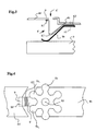
- FIG. 3 shows a top view corresponding to FIG. 2, which also compared to the top view in Fig.1 Is rotated 90 °.
- Figure 4 is a plan view of a 6-arm spring contact 5b along a line IV-IV in 3 in the direction of the connecting part 4b and its extension 4b 'reproduced.
- thermal protection 8 'approximately V-shaped the apex or Turn point 83 'of the V-shaped thermal fuse 8' again is arranged in the immediate vicinity of the PTC thermistor 3.
- Figure 4 Device has the extension 4b 'at its Plug contact 7b adjacent end of the separation point 6 a Circular or V-shaped indentation 41b '.
- the opposite edge area of the separation point 6 is preferred Complementary to the recess 41b 'executed.
- FIGS. 3 and 4 is a modified further development of a thermal fuse 8 'with its angled extension 81' on the left the extension 4b 'and with its other end 82' between the spring contact 5b and the connecting part 4b by means of a 3 by a dashed line and in FIG. 4 by a Point indicated rivets 10 attached.
- the apex or reversal point 83 'of the V-shaped thermal fuse 8' can also be arranged between two arms 5b 1 and 5b 2 of the 6-arm spring contact 5b. In this way, the distance between the thermistor 3 to be protected against overheating and the thermal fuse 8 'can be kept particularly small.
- the rivet When retrofitting with the thermal fuse 8 'according to 3 and 4, on the other hand, the rivet would have to be drilled out by means of which the 6-armed spring contact 5b on the connecting part 4b is attached. After insertion of the extension 82 'of the thermal Fuse 8 'between the connecting part 4b and the spring contact 5b are the connecting part by means of a new rivet 10 4b, the extension 82 'of the thermal fuse 8' and spring contact 5b to be firmly connected.
Description
- Fig.1
- eine schematische Draufsicht einer Motorstarteinrichtung mit Kaltleiter;
- Fig.2
- schematisch in Vergrößerung einen Teil eines Bereichs der in Fig.1 dargestellten Motorstarteinrichtung, in welchem gemäß der Erfindung eine bevorzugte Ausführungsform einer thermischen Sicherung untergebracht ist;
- Fig.3
- schematisch in Vergrößerung den Teil eines Bereichs der in Fig.1 dargestellten Motorstarteinrichtung, in welcher gemäß der Erfindung eine weitere bevorzugte Ausführungsform einer thermischen Sicherung untergebracht ist, und
- Fig.4
- schematisch ebenfalls vergrößert eine Draufsicht auf die in Fig.3 wiedergegebene Ausführung einer thermischen Sicherung.
Claims (5)
- Elektrische Einrichtung mit einer Einrichtung zum Schutz derselben vor Überhitzung durch eine thermische Sicherung (8, 8'), welche im Inneren eines Gehäuses (1) der gegen Überhitzen zu schützenden, elektrischen Einrichtung vorgesehen ist, bei welcher die thermische Sicherung (8, 8') in unmittelbarer Nähe eines kritischen Elements (3) der elektrischen Einrichtung vorgesehen ist, und bei welcher die thermische Sicherung (8, 8') aus niedrig schmelzendem Metall besteht,
dadurch gekennzeichnet,
daß die thermische Sicherung (8, 8') U- oder V-förmig ausgebildet und so angeordnet ist, daß deren Scheitelpunkt (83, 83') sich in unmittelbarer Nähe des kritischen Elements (3) befindet. - Elektrische Einrichtung nach Anspruch 1,
dadurch gekennzeichnet,
daß das kritische Element ein Kaltleiter (3) ist. - Elektrische Einrichtung nach Anspruch 1 oder 2,
dadurch gekennzeichnet,
daß das die elektrische Einrichtung umgebende Gehäuse (1) aus selbstverlöschendem Kunststoff besteht und/oder daß das Gehäuse (1) mit selbstverlöschendem Kunststoff ausgekleidet ist. - Verwendung einer elektrischen Einrichtung nach einem der Ansprüche 1 bis 3 bei einer Motorstarteinrichtung mit Kaltleiter, bei welcher eine mit einem Steckkontakt (7b) elektrisch leitend verbundene Verlängerung (4b') in der Nähe des Steckkontakts (7b) eine Trennstelle (6) aufweist, und abgewinkelte Enden (81, 82) der U-förmigen thermischen Sicherung (8) an einander gegenüberliegenden Rändern der Trennstelle (6) befestigt sind, so daß deren Scheitelpunkt (83) sehr nahe an den Kaltleiter (3) heranreicht.
- Verwendung einer elektrischen Einrichtung nach einem der Ansprüche 1 bis 3 bei einer Motorstarteinrichtung mit Kaltleiter, bei welcher eine mit einem Steckkontakt (7b) elektrisch leitend verbundene Verlängerung (4b') in der Nähe des Steckkontakts (7b) eine Trennstelle (6') aufweist, und an einem dem Steckkontakt (7b) benachbarten Ende der Verlängerung (4b') ein abgewinkelter Fortsatz (81') der V-förmigen thermischen Sicherung (8') befestigt ist, deren anderer Fortsatz (82') zwischen dem Anschlußteil (4b) und einem am Kaltleiter (3) anliegenden Federkontakt (5b) befestigt ist, so daß der Scheitel- oder Umkehrpunkt (83') der Sicherung (8) sehr nahe an den Kaltleiter (3) heranreicht.
Applications Claiming Priority (3)
| Application Number | Priority Date | Filing Date | Title |
|---|---|---|---|
| DE19639942 | 1996-09-27 | ||
| DE19639942A DE19639942C2 (de) | 1996-09-27 | 1996-09-27 | Thermische Sicherung |
| PCT/DE1997/002111 WO1998013846A1 (de) | 1996-09-27 | 1997-09-18 | Einrichtung zum schutz von elektrischen einrichtungen gegen überhitzen |
Publications (2)
| Publication Number | Publication Date |
|---|---|
| EP0928492A1 EP0928492A1 (de) | 1999-07-14 |
| EP0928492B1 true EP0928492B1 (de) | 2000-12-06 |
Family
ID=7807194
Family Applications (1)
| Application Number | Title | Priority Date | Filing Date |
|---|---|---|---|
| EP97909150A Expired - Lifetime EP0928492B1 (de) | 1996-09-27 | 1997-09-18 | Einrichtung zum schutz von elektrischen einrichtungen gegen überhitzen |
Country Status (11)
| Country | Link |
|---|---|
| US (1) | US6222715B1 (de) |
| EP (1) | EP0928492B1 (de) |
| JP (1) | JP2001504628A (de) |
| KR (1) | KR20000048633A (de) |
| CN (1) | CN1231759A (de) |
| AT (1) | ATE198008T1 (de) |
| BR (1) | BR9711577A (de) |
| DE (2) | DE19639942C2 (de) |
| DK (1) | DK0928492T3 (de) |
| ES (1) | ES2153184T3 (de) |
| WO (1) | WO1998013846A1 (de) |
Families Citing this family (25)
| Publication number | Priority date | Publication date | Assignee | Title |
|---|---|---|---|---|
| WO2003041855A1 (en) * | 2001-11-15 | 2003-05-22 | Powerspan Corp. | Discharge reactor fuse link |
| JP4119159B2 (ja) * | 2002-04-25 | 2008-07-16 | タイコ エレクトロニクス レイケム株式会社 | 温度保護素子 |
| KR20040065342A (ko) * | 2003-01-13 | 2004-07-22 | 자화전자 주식회사 | 피티시소자 파괴시 진행성을 방지하기 위한 안전모드 구조 |
| US7508651B2 (en) | 2003-07-09 | 2009-03-24 | Maxwell Technologies, Inc. | Dry particle based adhesive and dry film and methods of making same |
| US20050250011A1 (en) * | 2004-04-02 | 2005-11-10 | Maxwell Technologies, Inc. | Particle packaging systems and methods |
| US20060147712A1 (en) * | 2003-07-09 | 2006-07-06 | Maxwell Technologies, Inc. | Dry particle based adhesive electrode and methods of making same |
| US7791860B2 (en) | 2003-07-09 | 2010-09-07 | Maxwell Technologies, Inc. | Particle based electrodes and methods of making same |
| US7352558B2 (en) | 2003-07-09 | 2008-04-01 | Maxwell Technologies, Inc. | Dry particle based capacitor and methods of making same |
| US7342770B2 (en) * | 2003-07-09 | 2008-03-11 | Maxwell Technologies, Inc. | Recyclable dry particle based adhesive electrode and methods of making same |
| US7920371B2 (en) | 2003-09-12 | 2011-04-05 | Maxwell Technologies, Inc. | Electrical energy storage devices with separator between electrodes and methods for fabricating the devices |
| US7495349B2 (en) * | 2003-10-20 | 2009-02-24 | Maxwell Technologies, Inc. | Self aligning electrode |
| US7203056B2 (en) * | 2003-11-07 | 2007-04-10 | Maxwell Technologies, Inc. | Thermal interconnection for capacitor systems |
| US7180726B2 (en) * | 2003-11-07 | 2007-02-20 | Maxwell Technologies, Inc. | Self-supporting capacitor structure |
| US7027290B1 (en) | 2003-11-07 | 2006-04-11 | Maxwell Technologies, Inc. | Capacitor heat reduction apparatus and method |
| US7016177B1 (en) | 2003-11-07 | 2006-03-21 | Maxwell Technologies, Inc. | Capacitor heat protection |
| US7384433B2 (en) | 2004-02-19 | 2008-06-10 | Maxwell Technologies, Inc. | Densification of compressible layers during electrode lamination |
| US7090946B2 (en) | 2004-02-19 | 2006-08-15 | Maxwell Technologies, Inc. | Composite electrode and method for fabricating same |
| US20050269988A1 (en) * | 2004-06-04 | 2005-12-08 | Maxwell Technologies, Inc. | Voltage balancing circuit for multi-cell modules |
| US7440258B2 (en) | 2005-03-14 | 2008-10-21 | Maxwell Technologies, Inc. | Thermal interconnects for coupling energy storage devices |
| US7492574B2 (en) | 2005-03-14 | 2009-02-17 | Maxwell Technologies, Inc. | Coupling of cell to housing |
| JP2008508746A (ja) * | 2005-07-11 | 2008-03-21 | ジャーワ エレクトロニクス カンパニー リミテッド | セラミック素体の破壊時における伝播の防止のための安全装置 |
| US8518573B2 (en) * | 2006-09-29 | 2013-08-27 | Maxwell Technologies, Inc. | Low-inductive impedance, thermally decoupled, radii-modulated electrode core |
| US20080201925A1 (en) | 2007-02-28 | 2008-08-28 | Maxwell Technologies, Inc. | Ultracapacitor electrode with controlled sulfur content |
| US20080314893A1 (en) * | 2007-06-25 | 2008-12-25 | Adair Joel E | Heating device with adjusting electrical contact |
| US8174354B2 (en) * | 2010-07-23 | 2012-05-08 | Sensata Technologies Massachusetts, Inc. | Method and apparatus for control of failed thermistor devices |
Family Cites Families (16)
| Publication number | Priority date | Publication date | Assignee | Title |
|---|---|---|---|---|
| FR1244474A (fr) | 1959-09-24 | 1960-10-28 | Philips Nv | Fusible, notamment pour petits transformateurs |
| DE1906101U (de) * | 1964-07-30 | 1964-12-10 | Licentia Gmbh | Ueberhitzungsschutz. |
| DE2342015B2 (de) | 1973-08-20 | 1976-09-09 | Danfoss A/S, Nordborg (Dänemark) | Schutzeinrichtung fuer eine anlassanordnung fuer einphasen-asynchronmotoren |
| US4431983A (en) * | 1980-08-29 | 1984-02-14 | Sprague Electric Company | PTCR Package |
| US4422120A (en) | 1980-10-13 | 1983-12-20 | Murata Manufacturing Co., Ltd. | Combination starter-protector device |
| DE3234826A1 (de) | 1982-09-21 | 1984-03-22 | Loewe Opta Gmbh, 8640 Kronach | Thermo-sicherungselement |
| US4728779A (en) * | 1985-09-27 | 1988-03-01 | Tdk Corporation | PTC heating device |
| US5153555A (en) * | 1989-11-28 | 1992-10-06 | Murata Manufacturing Co., Ltd. | Electronic device comprising a plate-shaped electronic element and a support and overcurrent protector for the same |
| DE4209542C2 (de) * | 1992-03-24 | 1995-07-06 | Roederstein Kondensatoren | Schmelzsicherung mit Federarm |
| DE4219304C2 (de) * | 1992-06-12 | 1994-03-31 | Roederstein Kondensatoren | Zuverlässiges Überstrom-Schutzbauteil mit geringem Platzbedarf und einfachem Aufbau |
| US5471035A (en) * | 1993-10-22 | 1995-11-28 | Eaton Corporation | Sandwich construction for current limiting positive temperature coefficient protective device |
| JP3358677B2 (ja) | 1993-12-30 | 2002-12-24 | 内橋エステック株式会社 | 薄型ヒュ−ズ |
| JPH07335408A (ja) * | 1994-06-10 | 1995-12-22 | Murata Mfg Co Ltd | 発熱電子部品 |
| AU2906995A (en) | 1994-06-22 | 1996-01-15 | Littelfuse, Inc. | Improved dual element circuit protection device |
| DE19514853C2 (de) * | 1995-04-26 | 1997-02-27 | Marcel Hofsaes | Temperaturwächter mit einem bei Übertemperatur schaltenden Bimetall-Schaltwerk |
| US5708553A (en) * | 1996-07-18 | 1998-01-13 | Hung; Je | Automatic switching-off structure for protecting electronic device from burning |
-
1996
- 1996-09-27 DE DE19639942A patent/DE19639942C2/de not_active Expired - Fee Related
-
1997
- 1997-09-18 ES ES97909150T patent/ES2153184T3/es not_active Expired - Lifetime
- 1997-09-18 KR KR1019990702574A patent/KR20000048633A/ko not_active Application Discontinuation
- 1997-09-18 AT AT97909150T patent/ATE198008T1/de not_active IP Right Cessation
- 1997-09-18 BR BR9711577A patent/BR9711577A/pt unknown
- 1997-09-18 WO PCT/DE1997/002111 patent/WO1998013846A1/de not_active Application Discontinuation
- 1997-09-18 JP JP51514698A patent/JP2001504628A/ja active Pending
- 1997-09-18 DE DE59702740T patent/DE59702740D1/de not_active Expired - Fee Related
- 1997-09-18 US US09/269,525 patent/US6222715B1/en not_active Expired - Fee Related
- 1997-09-18 EP EP97909150A patent/EP0928492B1/de not_active Expired - Lifetime
- 1997-09-18 DK DK97909150T patent/DK0928492T3/da active
- 1997-09-18 CN CN97198332A patent/CN1231759A/zh active Pending
Also Published As
| Publication number | Publication date |
|---|---|
| ES2153184T3 (es) | 2001-02-16 |
| DE59702740D1 (de) | 2001-01-11 |
| DE19639942A1 (de) | 1998-04-02 |
| EP0928492A1 (de) | 1999-07-14 |
| BR9711577A (pt) | 1999-08-24 |
| ATE198008T1 (de) | 2000-12-15 |
| DE19639942C2 (de) | 1999-07-01 |
| KR20000048633A (ko) | 2000-07-25 |
| WO1998013846A1 (de) | 1998-04-02 |
| CN1231759A (zh) | 1999-10-13 |
| JP2001504628A (ja) | 2001-04-03 |
| DK0928492T3 (da) | 2001-03-05 |
| US6222715B1 (en) | 2001-04-24 |
Similar Documents
| Publication | Publication Date | Title |
|---|---|---|
| EP0928492B1 (de) | Einrichtung zum schutz von elektrischen einrichtungen gegen überhitzen | |
| EP2601715B1 (de) | Thermische überlastschutzvorrichtung | |
| EP2059933B1 (de) | Überspannungsableiter mit einem gehäuse und mit mindestens einem ableitelement | |
| DE112004002301T5 (de) | Elektrische Schutzeinrichtung für ein Fahrzeug und System, das diese einsetzt | |
| DE3140462C2 (de) | ||
| EP3621415B1 (de) | Elektronische baugruppe mit thermosicherung | |
| DE602005005217T2 (de) | Versorgungsschaltung für eine elektromotorbürste insbesondere eines kraftfahrzeug-anlassers | |
| WO2009106461A2 (de) | Strom-überlastschutz einer elektrischen maschine | |
| WO2002021555A1 (de) | Überlastschutz | |
| EP0258562B1 (de) | Schmelzsicherung, insbesondere für Elektromotore | |
| EP0931321B1 (de) | Kontaktgruppe mit einem kaltleiter | |
| EP1075010A2 (de) | Halbleiterschalter | |
| DE112012002681T5 (de) | Motorschutzschalter | |
| DE10148488B4 (de) | Anlasser mit Überhitzungsschutzeinrichtung einschließlich einer Bürsteneinrichtung | |
| DE1563878A1 (de) | Thermische Sicherung unter Ausnutzung einer elektrisch leitenden Pille | |
| DE2811503C2 (de) | Schutzeinrichtung gegen Wärmeüberlastung eines thermisch hoch belastbaren Elektro-Kleinmotors | |
| WO2004109902A1 (de) | Worwiderstandsbaugruppe für einen elektromotor und schaltungsanordnung mit einer vorwiderstandsbaugruppe zum betreiben eines elektromotors sowie verwendung einer vorwiderstandsbaugruppe | |
| DE10311090A1 (de) | Thermische Sicherung | |
| DE102006048104A1 (de) | Thermischer Überlastschutz | |
| EP1577906A2 (de) | Sicherung mit einem seinen elektrischen Widerstand bei einer Temperaturerhöhung vergrössernden Bauelement | |
| WO1997030463A1 (de) | Sicherheitseinrichtung | |
| DE60122638T2 (de) | Thermisch ansprechbare Schutzvorrichtung für Elektromotoren | |
| DE3106024C2 (de) | Zigarrenanzünder | |
| EP0973184A1 (de) | Elektrisches Sicherungselement mit zwischen Anschlussstücken angeordnetem Schmelzstreifen | |
| WO2001008179A1 (de) | Schaltsystem mit kombinierter schalt- und blockiervorrichtung |
Legal Events
| Date | Code | Title | Description |
|---|---|---|---|
| PUAI | Public reference made under article 153(3) epc to a published international application that has entered the european phase |
Free format text: ORIGINAL CODE: 0009012 |
|
| 17P | Request for examination filed |
Effective date: 19990319 |
|
| AK | Designated contracting states |
Kind code of ref document: A1 Designated state(s): AT DE DK ES FR GB IT |
|
| GRAG | Despatch of communication of intention to grant |
Free format text: ORIGINAL CODE: EPIDOS AGRA |
|
| 17Q | First examination report despatched |
Effective date: 19991103 |
|
| GRAG | Despatch of communication of intention to grant |
Free format text: ORIGINAL CODE: EPIDOS AGRA |
|
| GRAH | Despatch of communication of intention to grant a patent |
Free format text: ORIGINAL CODE: EPIDOS IGRA |
|
| RAP1 | Party data changed (applicant data changed or rights of an application transferred) |
Owner name: EPCOS AG |
|
| GRAH | Despatch of communication of intention to grant a patent |
Free format text: ORIGINAL CODE: EPIDOS IGRA |
|
| GRAA | (expected) grant |
Free format text: ORIGINAL CODE: 0009210 |
|
| AK | Designated contracting states |
Kind code of ref document: B1 Designated state(s): AT DE DK ES FR GB IT |
|
| REF | Corresponds to: |
Ref document number: 198008 Country of ref document: AT Date of ref document: 20001215 Kind code of ref document: T |
|
| REF | Corresponds to: |
Ref document number: 59702740 Country of ref document: DE Date of ref document: 20010111 |
|
| ET | Fr: translation filed | ||
| REG | Reference to a national code |
Ref country code: ES Ref legal event code: FG2A Ref document number: 2153184 Country of ref document: ES Kind code of ref document: T3 |
|
| ITF | It: translation for a ep patent filed |
Owner name: STUDIO JAUMANN P. & C. S.N.C. |
|
| REG | Reference to a national code |
Ref country code: DK Ref legal event code: T3 |
|
| GBT | Gb: translation of ep patent filed (gb section 77(6)(a)/1977) |
Effective date: 20010220 |
|
| PLBE | No opposition filed within time limit |
Free format text: ORIGINAL CODE: 0009261 |
|
| STAA | Information on the status of an ep patent application or granted ep patent |
Free format text: STATUS: NO OPPOSITION FILED WITHIN TIME LIMIT |
|
| 26N | No opposition filed | ||
| REG | Reference to a national code |
Ref country code: GB Ref legal event code: IF02 |
|
| PGFP | Annual fee paid to national office [announced via postgrant information from national office to epo] |
Ref country code: DK Payment date: 20020902 Year of fee payment: 6 |
|
| PGFP | Annual fee paid to national office [announced via postgrant information from national office to epo] |
Ref country code: AT Payment date: 20020903 Year of fee payment: 6 |
|
| PGFP | Annual fee paid to national office [announced via postgrant information from national office to epo] |
Ref country code: ES Payment date: 20021009 Year of fee payment: 6 |
|
| PG25 | Lapsed in a contracting state [announced via postgrant information from national office to epo] |
Ref country code: AT Free format text: LAPSE BECAUSE OF NON-PAYMENT OF DUE FEES Effective date: 20030918 |
|
| PG25 | Lapsed in a contracting state [announced via postgrant information from national office to epo] |
Ref country code: ES Free format text: LAPSE BECAUSE OF NON-PAYMENT OF DUE FEES Effective date: 20030919 |
|
| PG25 | Lapsed in a contracting state [announced via postgrant information from national office to epo] |
Ref country code: DK Free format text: LAPSE BECAUSE OF NON-PAYMENT OF DUE FEES Effective date: 20030930 |
|
| REG | Reference to a national code |
Ref country code: DK Ref legal event code: EBP |
|
| PGFP | Annual fee paid to national office [announced via postgrant information from national office to epo] |
Ref country code: GB Payment date: 20040915 Year of fee payment: 8 |
|
| PGFP | Annual fee paid to national office [announced via postgrant information from national office to epo] |
Ref country code: FR Payment date: 20040920 Year of fee payment: 8 |
|
| REG | Reference to a national code |
Ref country code: ES Ref legal event code: FD2A Effective date: 20030919 |
|
| PG25 | Lapsed in a contracting state [announced via postgrant information from national office to epo] |
Ref country code: IT Free format text: LAPSE BECAUSE OF NON-PAYMENT OF DUE FEES;WARNING: LAPSES OF ITALIAN PATENTS WITH EFFECTIVE DATE BEFORE 2007 MAY HAVE OCCURRED AT ANY TIME BEFORE 2007. THE CORRECT EFFECTIVE DATE MAY BE DIFFERENT FROM THE ONE RECORDED. Effective date: 20050918 Ref country code: GB Free format text: LAPSE BECAUSE OF NON-PAYMENT OF DUE FEES Effective date: 20050918 |
|
| GBPC | Gb: european patent ceased through non-payment of renewal fee |
Effective date: 20050918 |
|
| PG25 | Lapsed in a contracting state [announced via postgrant information from national office to epo] |
Ref country code: FR Free format text: LAPSE BECAUSE OF NON-PAYMENT OF DUE FEES Effective date: 20060531 |
|
| REG | Reference to a national code |
Ref country code: FR Ref legal event code: ST Effective date: 20060531 |
|
| PGFP | Annual fee paid to national office [announced via postgrant information from national office to epo] |
Ref country code: DE Payment date: 20081031 Year of fee payment: 12 |
|
| PG25 | Lapsed in a contracting state [announced via postgrant information from national office to epo] |
Ref country code: DE Free format text: LAPSE BECAUSE OF NON-PAYMENT OF DUE FEES Effective date: 20100401 |