EP0928148B1 - Shelving stand - Google Patents
Shelving stand Download PDFInfo
- Publication number
- EP0928148B1 EP0928148B1 EP97929662A EP97929662A EP0928148B1 EP 0928148 B1 EP0928148 B1 EP 0928148B1 EP 97929662 A EP97929662 A EP 97929662A EP 97929662 A EP97929662 A EP 97929662A EP 0928148 B1 EP0928148 B1 EP 0928148B1
- Authority
- EP
- European Patent Office
- Prior art keywords
- shelf
- stand
- shelves
- stand according
- shelf stand
- Prior art date
- Legal status (The legal status is an assumption and is not a legal conclusion. Google has not performed a legal analysis and makes no representation as to the accuracy of the status listed.)
- Expired - Lifetime
Links
- 230000002093 peripheral effect Effects 0.000 claims abstract 2
- 239000002184 metal Substances 0.000 claims description 4
- 238000013016 damping Methods 0.000 claims description 2
- 230000000087 stabilizing effect Effects 0.000 claims 1
- 241000239290 Araneae Species 0.000 description 5
- 230000000694 effects Effects 0.000 description 3
- 238000000034 method Methods 0.000 description 3
- 230000032258 transport Effects 0.000 description 3
- 238000005096 rolling process Methods 0.000 description 2
- 230000006835 compression Effects 0.000 description 1
- 238000007906 compression Methods 0.000 description 1
- 230000001419 dependent effect Effects 0.000 description 1
- 230000002349 favourable effect Effects 0.000 description 1
- 239000000463 material Substances 0.000 description 1
- 238000012544 monitoring process Methods 0.000 description 1
- 239000000725 suspension Substances 0.000 description 1
Images





Classifications
-
- A—HUMAN NECESSITIES
- A47—FURNITURE; DOMESTIC ARTICLES OR APPLIANCES; COFFEE MILLS; SPICE MILLS; SUCTION CLEANERS IN GENERAL
- A47F—SPECIAL FURNITURE, FITTINGS, OR ACCESSORIES FOR SHOPS, STOREHOUSES, BARS, RESTAURANTS OR THE LIKE; PAYING COUNTERS
- A47F5/00—Show stands, hangers, or shelves characterised by their constructional features
- A47F5/02—Rotary display stands
- A47F5/025—Rotary display stands having mechanical drive, e.g. turntables
Definitions
- the present invention relates to a shelf stand having individually rotatable shelves located one above the other according to the preamble of claim 1.
- shelf stands with vertical columns and a plurality of circular shelves carried by the columns and located on top of each other. It is also known from said patent to make the contents of these shelves readily accessible in the order of use first in - first out.
- the shelf stands can be made in various sizes and will obtain thereby various storing capacities.
- EP-A-0 667 111 discloses a presentation table for loudspeakers in which a certain kind of speakers shall be turned to a monitoring place and connected to an electrical point.
- the table may be turned manually or by means of a motor. Only one shelf is shown which is not divided into sectors since the device is not related to the handling of goods.
- the present invention has for its main object to eliminate the inconvenience when operating large shelf stands of the kind mentioned introductorily, so as to facilitate the search for a particular product and searching time thus be minimized.
- Another object of the invention is to minimize the need for internal transports in shops, pharmacies, storage rooms and the like having computerized handling routines, where shelf stands of the said type are used.
- the present invention thus relates to a shelf stand of the type disclosed in EP-A-0 211 816 and includes a number of rotatable shelves 10, substantially circular, and situated one above the other, as illustrated in Fig. 1.
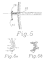
- Each shelf 10 is then provided at its periphery with a profiled section 11 shown in Fig. 6a and described in greater detail below, wherein a driving belt 12 is engaged, surrounding and running about shelf 10 and a driving gear 13 driven by a motor 14, such as an electric motor.
- Driving belt 12 can be e.g. a so called indented belt wheras the driven wheel, which is formed by shelf 10 itself and its curved circumferential section 11, need not be provided with teeth thanks to its large circumference in relation to that of the driving gear.
- the vast frictional surface suffices for allowing the two wheels to interactact without driving belt 12 slipping on section 11.
- the profilated section or rib 11 a cross section of which is shown in Fig. 6a, has a recess 11a for accomodating driving belt 12 and is preferably divided, for example, in four parts, provided along the periphery of shelf 10 to form together a wheel rim on the circular shelf.
- the rib has an attachment 11b by means of which it can be hooked on to shelf 10.
- a depression 11c for holding the rib together there is provided, in the bottom of said driving belt recess, a depression 11c, wherein a wire or similar tensioning means (not shown) can be located for pulling and holding together the rib by means of an appropriate wire tightener or wire joint.
- rib or section 11 is provided with a bore 11d in predetermined positions along the periphery of shelf 10 for accomodating an impulse generator 18, described in greater detail below, for determining the rotational position of shelf 10.
- Rib 11 is provided at its top with a label holder lie.
- edge flanges or walls can be secured for maintaining the goods on shelves 10 while they rotate.
- Fig. 6a illustrates another embodiment 55 of such a rib for a wheel-forming shelf having extendable cassettes according to Figs. 11a, 11b and 2b.
- Each circular shelf 10 is driven individually by its own motor 14, as shown in Figs. 1, 2a, 2b and 3.
- the speed and direction of rotation of motors 14 are preferably variable.
- Each motor 14 is suspended on vertical hinge-like supports 15, see Figs. 4 and 5, in turn suspended by a vertical stand or motor column 16, on which the motors are mounted one above the other, spaced the same distance as shelves 10, as shown in Figs. 1 and 3.
- At its top end motor column 16 is rigidly connected with the center shaft of the shelf stand and at its lower part likewise connected with the foot of the stand.
- Each hinge-like support 15 can be manipulated by means of an adjustment screw 20 threaded in column 16, the screw engaging a pressure plate carried in motor support 15.
- By screwing in adjustment screw 20 hinge-like support 15 is tilted outwards from shelf 10 so as to increase the distance beteen each shelf and driving gear 13 of its motor, thus tensioning driving belt 12.
- tensioning driving belt can be set to fit each motor driven shelf.
- Each shelf 10, which is substantially circular, is divided into an appropriate number of sector shaped panels, in the following designated shelf sectors 17, which are provided with an identification code, e.g. a number.
- shelf 10 is e.g. designed to include ten shelf sectors.
- Each such sector 17 is provided on its perimeter with an impulse generator 18 in the form of a magnet or the like, which cooperates with an impulse counter 19 in order to determine the position of shelf 10 in relationship to a fixed point on the shelf stand, e.g. on motor column 16.
- Singling out shelves 10 and deciding start, direction of rotation and speed of the motors is controlled e.g. by a computer, preferably the same computer used for other administrative areas of the general service operation.
- the shelf stand can also be provided with its own computer, having the limited capacity requested for control of its shelf operations.
- the starting position of shelf 10 and the position of the desired shelf sector 17 are both controlled by impulse counter 19.
- the shelf stand is preferably operated on the basis of the article number of the product sought for, the number being registered in the computer at one or more dispensing points, and registration can also be made from the point of replenishing. All these working stations are arranged in association with the periphery of the shelf stand, as will be described below.
- Fig. 7 is shown, in side view, another embodiment of the shelf stand according to the invention.
- the shelves are sloping and include extendable cassettes 34 which are slidable on brackets 27, which in turn are secured to a shelf spider, described more closely below.
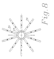
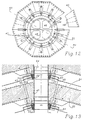
- Fig. 8 the basic framework or spider for the shelves is shown, said spider including a hub 34 and a plurality of spokes 25 corresponding to the number of shelf sectors 17, ten in the illustrated case.
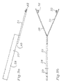
- Each spoke 25 has apertures 26 for securing a Y-shaped bracket 27, shown in Figs. 9a and 9b.
- Bracket 27 comprises a web 28 of square tube material provided with apertures 29 for mounting a bracket on each spoke 25 by means of apertures 26 therein. From web 28 of the bracket two shanks 30, 31 extend, which are provided at their outer ends with two upwardly facing wheels 32, 33 for carrying on the bracket an extendable cassette or tray.
- Cassette 34 shown in Figs.
- U-section 35 open downwards and is intended to be mounted straddling web 28 of the Y-bracket, in doing which a support roller 36, see below, is dismounted momentarily.
- a support roller 36 see below
- two support rollers 36 and 37 are provided for rolling on the underside and top side, respectively, of web 28 of Y-bracket 27.
- a box-shaped storage tray 38 is secured to cassette 34 and its U-section 35, the form of the tray corresponding to the form of a sector 17 of the shelf stand.
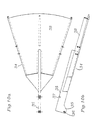
- cassette 34 Upon assembling cassette 34 and Y-bracket 27, support rollers 36, 37 will roll on web 28 of bracket 27, while the cassette tray 38 rests by its underside on bracket wheels 32, 33. Cassette 34 will then be extendable from a retracted position, shown in Fig. 11a where its rear end coincides with the rear end of bracket 27, to a position wherein it projects from the shelf stand, as shown in Fig. 11b.
- the pulling out of cassette 34 in relationship to bracket 27 will then be arrested by support roller 36 striking the apex end 40 of bracket shanks 30, 31.
- Said shanks are provided at their outer ends with lugs 42 for attaching a profilated section 55 snown in Fig. 6b, such section replacing section 11, described earlier and shown in Fig.
- Braking device 41 which dampens the outwardly directed movement of cassette 34 and assists in pushing it in to its retracted position.
- Braking device 41 which can also be provided with e.g. tension and compression springs, is shown in Figs. 11a and 11b in a design where a rubber cable sling is secured at one end within web 28 of the bracket and at its opposite end to U-web 35 of the cassette.
- each cassette 34 has an impulse generator 43 at its rear guiding members, cooperating without friction with a stationary impulse receiver 44 on the rotational shaft of the shelf stand, to indicate whether the cassette is in its retracted or extended position.
- the number of impulse receivers 44 twelve here, is then larger than the number of sectors or cassettes, which is ten, to exclude the possibility that an impulse receiver 44 becomes ineffective while landing at a joint between two sectors.
- another impulse generator 48 cooperating without friction with another impulse receiver 50, also tne position of cassette 34 in the direction of rotation of shelf 10 can be indicated.
- This arrangement is substituted for the impulse generators 18 of Fig. 2 mounted on the periphery of shelves 10. As can be seen from Fig.
- the rotating shaft 45 of the shelves comprises a metal channel section having channels 46 for leading cables to and from the motors and the impulse receivers or counters. Said shaft 45 is then provided with a surrounding, rigidly mounted tube shaft 47 having a retaining ring 52 for coacting with the ball bearings 54 and hub 24 of the shelves.
- selecting shelves 10, start/stop of the motors and their direction of rotation and speed can be controlled by a computer.
- the position of the shelves and the position of each shelf sector is controlled in both cases by means of the impulse counters.
- As to the extendable cassettes 34 whether any one cassette is extended or retracted is checked by means of impulse generators 43 and impulse receivers 44, to the effect that rotation of shelves 10 cannot commence when a cassette has been pulled out.
- the shelf stand is preferably operated at one or more dispense stations and also remotely, from the station where replenishing is carried out, preferably by registering in the computer the article number of any item sought for. All said working stations are arranged in association with the periphery of the shelf stand.
- Replenishing goods at the goods reception point is carried out such that the article number of each item is registered together with the number of the shelf sector 17 where the item is placed, which should be carried out in alphabetical order so that manual routines can be resorted to at service interruptions, as other so called picking machines or automatic storing facilities will be completely knocked out when electric or computer systems break down.
- the registration of the position of the goods will guide the automatic search process.
- Dispensing is carried out such that the article number of the item sought for is entered in the ordinary dispense procedure.
- An extra search impulse starts the search process in the shelf stand: selection of shelf 10, selection of shortest route and most favourable direction of rotation, selection of rotational speed - which should be higher when the distance between the starting point and the self sector 17 is great - and selection of the proper shelf sector 17, which is then moved forward towards the sales person.
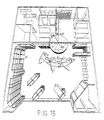
- Figs. 14 and 15 a perfect siting of the shelf stand according to the present invention is shown.
- the lay-out drawing according to Fig. 15 it is shown how half of the shelf stand, e.g. in a pharmacy, extends through a wall in the premises and the remaining part 23, i.e. two quarters of the stand, are found in a goods reception room 22 and a secondary space, respectively.
- the shelf stand is placed such that the motors are located in the secondary space behind a so called rolling store. This renders service possible while removing accident hazards. Transports from the reception room 22 are eliminated, as the rotating shelves 10 take care of moving the goods.
- shelf 10 When dispensing and picking from a shelf 10 is going on, other dispensing operations requested from this shelf are placed in queue order. As soon as the first dispense operation has been completed by a "release" impulse, shelf 10 will rotate forward to the next, newly requested position. There will be an essential gain of time when the shelf stand is advancing the proper shelf sector 17 at the same time as a service person carries out his or hers complete registry program while in contact with the customer.
- shelf stands with rotatable shelves 10 bring about great rationalization profits in the form of time and comfort.
- the lay-out described above which was made possible by the developed shelf stand, has the effect that the need for extra handling and internal transports of goods stored in the shelf stand is reduced.
Landscapes
- Mechanical Engineering (AREA)
- Engineering & Computer Science (AREA)
- Warehouses Or Storage Devices (AREA)
- Vending Machines For Individual Products (AREA)
- Pharmaceuticals Containing Other Organic And Inorganic Compounds (AREA)
- Liquid Crystal (AREA)
- Display Racks (AREA)
- Freezers Or Refrigerated Showcases (AREA)
- Transition And Organic Metals Composition Catalysts For Addition Polymerization (AREA)
- Transplanting Machines (AREA)
- Confectionery (AREA)
- Mushroom Cultivation (AREA)
- Liquid Crystal Substances (AREA)
- Particle Accelerators (AREA)
- Control Of Motors That Do Not Use Commutators (AREA)
Applications Claiming Priority (3)
| Application Number | Priority Date | Filing Date | Title |
|---|---|---|---|
| SE9603157 | 1996-08-30 | ||
| SE9603157A SE9603157L (sv) | 1996-08-30 | 1996-08-30 | Hyllställ carrousel 260 |
| PCT/SE1997/001114 WO1998009555A1 (en) | 1996-08-30 | 1997-06-23 | Shelving stand |
Publications (2)
| Publication Number | Publication Date |
|---|---|
| EP0928148A1 EP0928148A1 (en) | 1999-07-14 |
| EP0928148B1 true EP0928148B1 (en) | 2001-09-05 |
Family
ID=20403719
Family Applications (1)
| Application Number | Title | Priority Date | Filing Date |
|---|---|---|---|
| EP97929662A Expired - Lifetime EP0928148B1 (en) | 1996-08-30 | 1997-06-23 | Shelving stand |
Country Status (18)
| Country | Link |
|---|---|
| US (2) | US6196400B1 (cs) |
| EP (1) | EP0928148B1 (cs) |
| JP (1) | JP3884773B2 (cs) |
| CN (1) | CN1123312C (cs) |
| AT (1) | ATE205062T1 (cs) |
| AU (1) | AU718354B2 (cs) |
| CA (1) | CA2263487C (cs) |
| CZ (1) | CZ295439B6 (cs) |
| DE (1) | DE69706549T2 (cs) |
| DK (1) | DK0928148T3 (cs) |
| ES (1) | ES2163786T3 (cs) |
| HU (1) | HU221779B1 (cs) |
| NO (2) | NO312394B1 (cs) |
| PL (1) | PL183551B1 (cs) |
| PT (1) | PT928148E (cs) |
| RU (1) | RU2181980C2 (cs) |
| SE (1) | SE9603157L (cs) |
| WO (1) | WO1998009555A1 (cs) |
Families Citing this family (21)
| Publication number | Priority date | Publication date | Assignee | Title |
|---|---|---|---|---|
| SE9603157L (sv) * | 1996-08-30 | 1998-03-01 | Sintek Int Ab | Hyllställ carrousel 260 |
| US6611772B1 (en) | 1997-05-16 | 2003-08-26 | General Electric Company | Electronic electricity meter configurable to operate in a plurality of meter forms and ratings |
| GB9803684D0 (en) * | 1998-02-24 | 1998-04-15 | Genevac Ltd | Method and apparatus for controlling temperature during evaporation of samples |
| EP1820425B1 (de) * | 2004-12-29 | 2008-12-31 | GEBR. WILLACH GmbH | Rundregal |
| SE530595C2 (sv) * | 2006-11-13 | 2008-07-15 | Enjoy Group Ab | Hyllställ med en roterbar hyllsektion och gravitationsmatande hyllplan |
| US8267257B2 (en) * | 2007-03-09 | 2012-09-18 | Electrolux Home Products, Inc. | Turntable oven rack |
| KR100828966B1 (ko) * | 2007-12-12 | 2008-05-13 | 세대산전 주식회사 | 쇼케이스용 선반 |
| US7665685B2 (en) * | 2008-04-17 | 2010-02-23 | Deepflex, Inc. | Modular carousel assembly and method |
| USD611662S1 (en) * | 2009-04-15 | 2010-03-09 | Zenith Innovation, Llc | Bird feed tray |
| USD606334S1 (en) | 2009-05-13 | 2009-12-22 | Target Brands, Inc. | Display apparatus for products and product images |
| US20110079567A1 (en) * | 2009-10-01 | 2011-04-07 | Trena Anderson | Rotatable Shelf |
| USD623805S1 (en) * | 2009-12-29 | 2010-09-14 | Zenith Innovation, Llc | Modular bird feeder |
| USD638588S1 (en) * | 2010-12-28 | 2011-05-24 | Zenith Innovation, Llc | Hanging bird feeder |
| US20130193094A1 (en) * | 2012-01-12 | 2013-08-01 | EMS Mind Reader LLC | Supply pod carousel and method of making the same |
| US9022236B1 (en) * | 2012-02-20 | 2015-05-05 | Centricity Corporation | Rotary carousel apparatus and system |
| USD776462S1 (en) * | 2013-03-23 | 2017-01-17 | Michael Green | Pagoda soap tower |
| JP2018530106A (ja) | 2015-08-17 | 2018-10-11 | セルガード エルエルシー | 改良されたバッテリーセパレータおよび関連する方法 |
| CN105962698A (zh) * | 2016-06-30 | 2016-09-28 | 新蕾车业无锡有限公司 | 一种金属把手的销售架 |
| US10849425B2 (en) | 2017-10-06 | 2020-12-01 | The Intellectual Property Network, Inc. | Motorized modular smart shelving and storage unit |
| CN108814011B (zh) * | 2018-04-24 | 2020-02-11 | 窦彩艳 | 一种自动推码盒装药物的承载药架的工作方法 |
| KR101985618B1 (ko) * | 2018-04-28 | 2019-06-03 | 한남건 | 물품공급장치 |
Family Cites Families (17)
| Publication number | Priority date | Publication date | Assignee | Title |
|---|---|---|---|---|
| GB191111708A (en) * | 1911-05-15 | 1912-02-15 | T H Brooker & Company Ltd | Improvements in Devices for Advertising, or the Display of Goods. |
| GB191211708A (en) | 1912-05-16 | 1912-10-17 | John Gilbert Warfield | Improvements in the Method of and Apparatus for Numerical Education |
| US1608704A (en) * | 1923-03-22 | 1926-11-30 | John B Mcconaha | Self-serving table |
| US1653323A (en) * | 1926-02-27 | 1927-12-20 | Thomas A Taylor | Rotary store structure |
| US2338324A (en) * | 1943-04-06 | 1944-01-04 | Floyd Raymond Leslie | Rotary display merchandising system |
| FR1401294A (fr) * | 1964-04-20 | 1965-06-04 | Meuble rotatif à étagères, notamment pour restaurants à libre service | |
| FR1552245A (cs) * | 1967-11-24 | 1969-01-03 | ||
| US3565263A (en) * | 1969-12-05 | 1971-02-23 | Wright Barry Corp | Adjustable rotary file |
| US3872801A (en) | 1973-06-01 | 1975-03-25 | B W Metals Company Inc | Drive system for a rotating cafeteria type food service counter |
| DE2433302C3 (de) * | 1974-07-11 | 1981-07-23 | Jagenberg-Werke AG, 4000 Düsseldorf | Einrichtung zum Einstellen des gegenseitigen Abstandes mehrerer nebeneinander angeordneter Elemente, insbesondere von Messerpaaren zum Längsschneiden von Bahnmaterial |
| FI85800C (fi) * | 1985-08-01 | 1992-06-10 | Sintek Ab | Hyllstaell. |
| EP0272345B1 (de) * | 1986-12-24 | 1991-05-15 | Wilhelm Hegenscheidt Gesellschaft mbH | Verfahren und Einrichtung zur Beeinflussung der Bewegung eines beweglichen Organs, insbesondere eines Werkzeugträgers |
| US4938549A (en) * | 1989-11-03 | 1990-07-03 | Datum Filing Systems, Inc. | Rotary file unit and cabinet |
| FI85095C (fi) * | 1990-08-20 | 1992-03-10 | Hyllyset Oy | Hylla. |
| US6072766A (en) | 1993-10-22 | 2000-06-06 | Storage Technology Corporation | Apparatus and associated method for storing, retrieving, and manipulating computer, mass-storage media elements |
| DE9402394U1 (de) * | 1994-02-14 | 1994-04-07 | Gerkinsmeyer, Norman, 87700 Memmingen | Drehtisch mit mehreren Lautsprecherboxen |
| SE9603157L (sv) * | 1996-08-30 | 1998-03-01 | Sintek Int Ab | Hyllställ carrousel 260 |
-
1996
- 1996-08-30 SE SE9603157A patent/SE9603157L/ not_active Application Discontinuation
-
1997
- 1997-06-23 HU HU9902837A patent/HU221779B1/hu not_active IP Right Cessation
- 1997-06-23 PL PL97331711A patent/PL183551B1/pl not_active IP Right Cessation
- 1997-06-23 WO PCT/SE1997/001114 patent/WO1998009555A1/en not_active Ceased
- 1997-06-23 PT PT97929662T patent/PT928148E/pt unknown
- 1997-06-23 RU RU99106514/12A patent/RU2181980C2/ru not_active IP Right Cessation
- 1997-06-23 CZ CZ1999618A patent/CZ295439B6/cs not_active IP Right Cessation
- 1997-06-23 EP EP97929662A patent/EP0928148B1/en not_active Expired - Lifetime
- 1997-06-23 DK DK97929662T patent/DK0928148T3/da active
- 1997-06-23 CA CA002263487A patent/CA2263487C/en not_active Expired - Fee Related
- 1997-06-23 AU AU33670/97A patent/AU718354B2/en not_active Ceased
- 1997-06-23 AT AT97929662T patent/ATE205062T1/de not_active IP Right Cessation
- 1997-06-23 ES ES97929662T patent/ES2163786T3/es not_active Expired - Lifetime
- 1997-06-23 US US09/242,795 patent/US6196400B1/en not_active Expired - Lifetime
- 1997-06-23 CN CN97197474A patent/CN1123312C/zh not_active Expired - Fee Related
- 1997-06-23 DE DE69706549T patent/DE69706549T2/de not_active Expired - Fee Related
- 1997-06-23 JP JP51203298A patent/JP3884773B2/ja not_active Expired - Fee Related
-
1999
- 1999-02-22 NO NO19990842A patent/NO312394B1/no not_active IP Right Cessation
- 1999-02-24 NO NO990868A patent/NO990868D0/no unknown
-
2000
- 2000-12-22 US US09/747,855 patent/US6328172B2/en not_active Expired - Fee Related
Also Published As
| Publication number | Publication date |
|---|---|
| NO990842L (no) | 1999-04-08 |
| US20010000896A1 (en) | 2001-05-10 |
| RU2181980C2 (ru) | 2002-05-10 |
| CA2263487A1 (en) | 1998-03-12 |
| NO990868D0 (no) | 1999-02-24 |
| CN1123312C (zh) | 2003-10-08 |
| HUP9902837A2 (hu) | 1999-12-28 |
| PL183551B1 (pl) | 2002-06-28 |
| DK0928148T3 (da) | 2002-01-07 |
| ES2163786T3 (es) | 2002-02-01 |
| HU221779B1 (hu) | 2003-01-28 |
| CZ295439B6 (cs) | 2005-08-17 |
| CA2263487C (en) | 2006-12-19 |
| NO990842D0 (no) | 1999-02-22 |
| WO1998009555A1 (en) | 1998-03-12 |
| PT928148E (pt) | 2002-02-28 |
| JP3884773B2 (ja) | 2007-02-21 |
| US6328172B2 (en) | 2001-12-11 |
| ATE205062T1 (de) | 2001-09-15 |
| SE9603157L (sv) | 1998-03-01 |
| US6196400B1 (en) | 2001-03-06 |
| EP0928148A1 (en) | 1999-07-14 |
| NO312394B1 (no) | 2002-05-06 |
| DE69706549D1 (de) | 2001-10-11 |
| DE69706549T2 (de) | 2002-05-08 |
| AU3367097A (en) | 1998-03-26 |
| SE9603157D0 (sv) | 1996-08-30 |
| PL331711A1 (en) | 1999-08-02 |
| CN1228683A (zh) | 1999-09-15 |
| HUP9902837A3 (en) | 2000-08-28 |
| CZ61899A3 (cs) | 2000-02-16 |
| AU718354B2 (en) | 2000-04-13 |
| JP2000517219A (ja) | 2000-12-26 |
Similar Documents
| Publication | Publication Date | Title |
|---|---|---|
| US6328172B2 (en) | Shelving stand | |
| WO1998009555A9 (en) | Shelving stand | |
| US9623995B2 (en) | Core pin bag dispenser | |
| US5131499A (en) | Retail store checkout device | |
| CA1295294C (en) | Through-counter dispensing system for plastic bags | |
| US20050063801A1 (en) | Method and automated system for storing and distributing various objects or articles | |
| US5570809A (en) | Adhesive label dispenser | |
| US2338324A (en) | Rotary display merchandising system | |
| US20030196978A1 (en) | Rotating bath bar and ceiling glass fixture display carousel system | |
| US5086935A (en) | Dispensing rack with movably positionable hangers | |
| US3872801A (en) | Drive system for a rotating cafeteria type food service counter | |
| US6305045B1 (en) | Paint supply and finishing system | |
| WO1994023619A1 (en) | Cabinets for foodstuffs in containers | |
| US20230405798A1 (en) | Rotatable tool organizer | |
| KR200210918Y1 (ko) | 회전식 상품 진열대 | |
| US3701457A (en) | Cup dispenser with revolving adapter | |
| CN219077866U (zh) | 卷烟标签收纳盒 | |
| WO2010117336A1 (en) | Helical coil dispenser for vending machine | |
| GB2126987A (en) | Roll support and dispenser | |
| CA1157822A (en) | Display and dispensing rack for filamentary material | |
| IES66915B2 (en) | Dispensing system for merchandise | |
| JP2000203517A (ja) | テ―プ巻き機の物品支持台 | |
| CA2351451A1 (en) | Multi functional apparatus |
Legal Events
| Date | Code | Title | Description |
|---|---|---|---|
| PUAI | Public reference made under article 153(3) epc to a published international application that has entered the european phase |
Free format text: ORIGINAL CODE: 0009012 |
|
| 17P | Request for examination filed |
Effective date: 19990315 |
|
| AK | Designated contracting states |
Kind code of ref document: A1 Designated state(s): AT BE CH DE DK ES FI FR GB IE IT LI NL PT SE |
|
| R17P | Request for examination filed (corrected) |
Effective date: 19990315 |
|
| 17Q | First examination report despatched |
Effective date: 20000314 |
|
| GRAG | Despatch of communication of intention to grant |
Free format text: ORIGINAL CODE: EPIDOS AGRA |
|
| GRAG | Despatch of communication of intention to grant |
Free format text: ORIGINAL CODE: EPIDOS AGRA |
|
| GRAH | Despatch of communication of intention to grant a patent |
Free format text: ORIGINAL CODE: EPIDOS IGRA |
|
| GRAH | Despatch of communication of intention to grant a patent |
Free format text: ORIGINAL CODE: EPIDOS IGRA |
|
| GRAA | (expected) grant |
Free format text: ORIGINAL CODE: 0009210 |
|
| AK | Designated contracting states |
Kind code of ref document: B1 Designated state(s): AT BE CH DE DK ES FI FR GB IE IT LI NL PT SE |
|
| REF | Corresponds to: |
Ref document number: 205062 Country of ref document: AT Date of ref document: 20010915 Kind code of ref document: T |
|
| REG | Reference to a national code |
Ref country code: CH Ref legal event code: EP |
|
| REF | Corresponds to: |
Ref document number: 69706549 Country of ref document: DE Date of ref document: 20011011 |
|
| REG | Reference to a national code |
Ref country code: CH Ref legal event code: NV Representative=s name: KIRKER & CIE SA |
|
| REG | Reference to a national code |
Ref country code: IE Ref legal event code: FG4D |
|
| ET | Fr: translation filed | ||
| REG | Reference to a national code |
Ref country code: GB Ref legal event code: IF02 |
|
| REG | Reference to a national code |
Ref country code: DK Ref legal event code: T3 |
|
| REG | Reference to a national code |
Ref country code: ES Ref legal event code: FG2A Ref document number: 2163786 Country of ref document: ES Kind code of ref document: T3 |
|
| REG | Reference to a national code |
Ref country code: PT Ref legal event code: SC4A Free format text: AVAILABILITY OF NATIONAL TRANSLATION Effective date: 20011120 |
|
| PLBE | No opposition filed within time limit |
Free format text: ORIGINAL CODE: 0009261 |
|
| STAA | Information on the status of an ep patent application or granted ep patent |
Free format text: STATUS: NO OPPOSITION FILED WITHIN TIME LIMIT |
|
| 26N | No opposition filed | ||
| PGFP | Annual fee paid to national office [announced via postgrant information from national office to epo] |
Ref country code: PT Payment date: 20070601 Year of fee payment: 11 |
|
| PGFP | Annual fee paid to national office [announced via postgrant information from national office to epo] |
Ref country code: CH Payment date: 20070614 Year of fee payment: 11 |
|
| PGFP | Annual fee paid to national office [announced via postgrant information from national office to epo] |
Ref country code: BE Payment date: 20070615 Year of fee payment: 11 |
|
| PGFP | Annual fee paid to national office [announced via postgrant information from national office to epo] |
Ref country code: ES Payment date: 20070621 Year of fee payment: 11 Ref country code: IE Payment date: 20070621 Year of fee payment: 11 |
|
| PGFP | Annual fee paid to national office [announced via postgrant information from national office to epo] |
Ref country code: AT Payment date: 20070622 Year of fee payment: 11 |
|
| PGFP | Annual fee paid to national office [announced via postgrant information from national office to epo] |
Ref country code: IT Payment date: 20070616 Year of fee payment: 11 |
|
| PGFP | Annual fee paid to national office [announced via postgrant information from national office to epo] |
Ref country code: FR Payment date: 20070531 Year of fee payment: 11 |
|
| BERE | Be: lapsed |
Owner name: *SINTEK INTERNATIONAL A.B. Effective date: 20080630 |
|
| REG | Reference to a national code |
Ref country code: PT Ref legal event code: MM4A Free format text: LAPSE DUE TO NON-PAYMENT OF FEES Effective date: 20081223 |
|
| PG25 | Lapsed in a contracting state [announced via postgrant information from national office to epo] |
Ref country code: PT Free format text: LAPSE BECAUSE OF NON-PAYMENT OF DUE FEES Effective date: 20081223 |
|
| REG | Reference to a national code |
Ref country code: CH Ref legal event code: PL |
|
| PG25 | Lapsed in a contracting state [announced via postgrant information from national office to epo] |
Ref country code: BE Free format text: LAPSE BECAUSE OF NON-PAYMENT OF DUE FEES Effective date: 20080630 |
|
| REG | Reference to a national code |
Ref country code: IE Ref legal event code: MM4A |
|
| REG | Reference to a national code |
Ref country code: FR Ref legal event code: ST Effective date: 20090228 |
|
| PG25 | Lapsed in a contracting state [announced via postgrant information from national office to epo] |
Ref country code: IE Free format text: LAPSE BECAUSE OF NON-PAYMENT OF DUE FEES Effective date: 20080623 Ref country code: AT Free format text: LAPSE BECAUSE OF NON-PAYMENT OF DUE FEES Effective date: 20080623 |
|
| PG25 | Lapsed in a contracting state [announced via postgrant information from national office to epo] |
Ref country code: LI Free format text: LAPSE BECAUSE OF NON-PAYMENT OF DUE FEES Effective date: 20080630 Ref country code: CH Free format text: LAPSE BECAUSE OF NON-PAYMENT OF DUE FEES Effective date: 20080630 |
|
| PGFP | Annual fee paid to national office [announced via postgrant information from national office to epo] |
Ref country code: NL Payment date: 20090625 Year of fee payment: 13 Ref country code: DK Payment date: 20090622 Year of fee payment: 13 |
|
| REG | Reference to a national code |
Ref country code: ES Ref legal event code: FD2A Effective date: 20080624 |
|
| PG25 | Lapsed in a contracting state [announced via postgrant information from national office to epo] |
Ref country code: IT Free format text: LAPSE BECAUSE OF NON-PAYMENT OF DUE FEES Effective date: 20080623 Ref country code: FR Free format text: LAPSE BECAUSE OF NON-PAYMENT OF DUE FEES Effective date: 20080630 |
|
| PGFP | Annual fee paid to national office [announced via postgrant information from national office to epo] |
Ref country code: FI Payment date: 20090617 Year of fee payment: 13 |
|
| PG25 | Lapsed in a contracting state [announced via postgrant information from national office to epo] |
Ref country code: ES Free format text: LAPSE BECAUSE OF NON-PAYMENT OF DUE FEES Effective date: 20080624 |
|
| PGFP | Annual fee paid to national office [announced via postgrant information from national office to epo] |
Ref country code: GB Payment date: 20090630 Year of fee payment: 13 Ref country code: DE Payment date: 20090626 Year of fee payment: 13 |
|
| REG | Reference to a national code |
Ref country code: NL Ref legal event code: V1 Effective date: 20110101 |
|
| PG25 | Lapsed in a contracting state [announced via postgrant information from national office to epo] |
Ref country code: FI Free format text: LAPSE BECAUSE OF NON-PAYMENT OF DUE FEES Effective date: 20100623 |
|
| REG | Reference to a national code |
Ref country code: DK Ref legal event code: EBP |
|
| GBPC | Gb: european patent ceased through non-payment of renewal fee |
Effective date: 20100623 |
|
| PG25 | Lapsed in a contracting state [announced via postgrant information from national office to epo] |
Ref country code: DE Free format text: LAPSE BECAUSE OF NON-PAYMENT OF DUE FEES Effective date: 20110101 |
|
| PG25 | Lapsed in a contracting state [announced via postgrant information from national office to epo] |
Ref country code: NL Free format text: LAPSE BECAUSE OF NON-PAYMENT OF DUE FEES Effective date: 20110101 |
|
| PG25 | Lapsed in a contracting state [announced via postgrant information from national office to epo] |
Ref country code: GB Free format text: LAPSE BECAUSE OF NON-PAYMENT OF DUE FEES Effective date: 20100623 |
|
| PGFP | Annual fee paid to national office [announced via postgrant information from national office to epo] |
Ref country code: SE Payment date: 20110622 Year of fee payment: 15 |
|
| PG25 | Lapsed in a contracting state [announced via postgrant information from national office to epo] |
Ref country code: DK Free format text: LAPSE BECAUSE OF NON-PAYMENT OF DUE FEES Effective date: 20100630 |
|
| REG | Reference to a national code |
Ref country code: SE Ref legal event code: EUG |
|
| PG25 | Lapsed in a contracting state [announced via postgrant information from national office to epo] |
Ref country code: SE Free format text: LAPSE BECAUSE OF NON-PAYMENT OF DUE FEES Effective date: 20120624 |