EP0927091B1 - Vorrichtung zum automatisierten setzen von haltebolzen auf trägerflächen - Google Patents
Vorrichtung zum automatisierten setzen von haltebolzen auf trägerflächen Download PDFInfo
- Publication number
- EP0927091B1 EP0927091B1 EP97909272A EP97909272A EP0927091B1 EP 0927091 B1 EP0927091 B1 EP 0927091B1 EP 97909272 A EP97909272 A EP 97909272A EP 97909272 A EP97909272 A EP 97909272A EP 0927091 B1 EP0927091 B1 EP 0927091B1
- Authority
- EP
- European Patent Office
- Prior art keywords
- stud
- inductor
- housing
- holding
- bolt
- Prior art date
- Legal status (The legal status is an assumption and is not a legal conclusion. Google has not performed a legal analysis and makes no representation as to the accuracy of the status listed.)
- Expired - Lifetime
Links
- 239000000853 adhesive Substances 0.000 claims abstract description 27
- 230000001070 adhesive effect Effects 0.000 claims abstract description 27
- 230000006698 induction Effects 0.000 claims abstract description 9
- 238000003825 pressing Methods 0.000 claims description 15
- 238000012546 transfer Methods 0.000 claims description 12
- 239000004831 Hot glue Substances 0.000 claims description 6
- 238000013016 damping Methods 0.000 claims description 4
- 238000004026 adhesive bonding Methods 0.000 claims description 3
- 230000001154 acute effect Effects 0.000 claims description 2
- 238000012545 processing Methods 0.000 claims description 2
- 230000003213 activating effect Effects 0.000 claims 1
- 230000001939 inductive effect Effects 0.000 claims 1
- 238000011017 operating method Methods 0.000 claims 1
- 238000000034 method Methods 0.000 description 5
- 239000012790 adhesive layer Substances 0.000 description 4
- 238000003780 insertion Methods 0.000 description 4
- 238000006073 displacement reaction Methods 0.000 description 3
- 230000037431 insertion Effects 0.000 description 3
- 238000002844 melting Methods 0.000 description 3
- 230000008018 melting Effects 0.000 description 3
- 238000013461 design Methods 0.000 description 2
- 239000003292 glue Substances 0.000 description 2
- 238000010438 heat treatment Methods 0.000 description 2
- 229920000914 Metallic fiber Polymers 0.000 description 1
- 238000007373 indentation Methods 0.000 description 1
- 238000009434 installation Methods 0.000 description 1
- 239000010410 layer Substances 0.000 description 1
- 239000000155 melt Substances 0.000 description 1
- 230000005855 radiation Effects 0.000 description 1
- 239000012815 thermoplastic material Substances 0.000 description 1
- 238000004804 winding Methods 0.000 description 1
Images

Classifications
-
- B—PERFORMING OPERATIONS; TRANSPORTING
- B23—MACHINE TOOLS; METAL-WORKING NOT OTHERWISE PROVIDED FOR
- B23P—METAL-WORKING NOT OTHERWISE PROVIDED FOR; COMBINED OPERATIONS; UNIVERSAL MACHINE TOOLS
- B23P19/00—Machines for simply fitting together or separating metal parts or objects, or metal and non-metal parts, whether or not involving some deformation; Tools or devices therefor so far as not provided for in other classes
-
- B—PERFORMING OPERATIONS; TRANSPORTING
- B23—MACHINE TOOLS; METAL-WORKING NOT OTHERWISE PROVIDED FOR
- B23P—METAL-WORKING NOT OTHERWISE PROVIDED FOR; COMBINED OPERATIONS; UNIVERSAL MACHINE TOOLS
- B23P19/00—Machines for simply fitting together or separating metal parts or objects, or metal and non-metal parts, whether or not involving some deformation; Tools or devices therefor so far as not provided for in other classes
- B23P19/04—Machines for simply fitting together or separating metal parts or objects, or metal and non-metal parts, whether or not involving some deformation; Tools or devices therefor so far as not provided for in other classes for assembling or disassembling parts
-
- B—PERFORMING OPERATIONS; TRANSPORTING
- B23—MACHINE TOOLS; METAL-WORKING NOT OTHERWISE PROVIDED FOR
- B23P—METAL-WORKING NOT OTHERWISE PROVIDED FOR; COMBINED OPERATIONS; UNIVERSAL MACHINE TOOLS
- B23P19/00—Machines for simply fitting together or separating metal parts or objects, or metal and non-metal parts, whether or not involving some deformation; Tools or devices therefor so far as not provided for in other classes
- B23P19/001—Article feeders for assembling machines
- B23P19/006—Holding or positioning the article in front of the applying tool
-
- Y—GENERAL TAGGING OF NEW TECHNOLOGICAL DEVELOPMENTS; GENERAL TAGGING OF CROSS-SECTIONAL TECHNOLOGIES SPANNING OVER SEVERAL SECTIONS OF THE IPC; TECHNICAL SUBJECTS COVERED BY FORMER USPC CROSS-REFERENCE ART COLLECTIONS [XRACs] AND DIGESTS
- Y10—TECHNICAL SUBJECTS COVERED BY FORMER USPC
- Y10T—TECHNICAL SUBJECTS COVERED BY FORMER US CLASSIFICATION
- Y10T156/00—Adhesive bonding and miscellaneous chemical manufacture
- Y10T156/10—Methods of surface bonding and/or assembly therefor
- Y10T156/1089—Methods of surface bonding and/or assembly therefor of discrete laminae to single face of additional lamina
-
- Y—GENERAL TAGGING OF NEW TECHNOLOGICAL DEVELOPMENTS; GENERAL TAGGING OF CROSS-SECTIONAL TECHNOLOGIES SPANNING OVER SEVERAL SECTIONS OF THE IPC; TECHNICAL SUBJECTS COVERED BY FORMER USPC CROSS-REFERENCE ART COLLECTIONS [XRACs] AND DIGESTS
- Y10—TECHNICAL SUBJECTS COVERED BY FORMER USPC
- Y10T—TECHNICAL SUBJECTS COVERED BY FORMER US CLASSIFICATION
- Y10T156/00—Adhesive bonding and miscellaneous chemical manufacture
- Y10T156/17—Surface bonding means and/or assemblymeans with work feeding or handling means
Definitions
- the invention relates to a device for automated setting and Glue retaining bolts on support surfaces, the retaining bolts with Disc collars are provided, which on their underside with a dry, through Heat-reactive hot-melt adhesive are coated.
- a device for the automated setting of fastening elements which is concerned with the thermal pressure installation of the fastening elements in cold workpieces made of thermoplastic material.
- metallic thread inserts are heated to the melting temperature by means of a heatable abutment and then pressed into the workpiece by means of a mandrel.
- the device consists of an elongated housing with a collecting device for the threaded inserts and a feed channel, which at its out of the Housing protruding end is connected to a flexible feed hose, through which the threaded inserts into the collecting device by means of compressed air be promoted.
- a bundled infrared radiation is used to warm up the thread insert used, which in conjunction with reflectors ensures that the complete Thread insert is heated to the indentation temperature in a relatively short time.
- This Device is not for gluing holding bolts coated with adhesive Suitable because the collecting device is not used to hold and warm up the Adhesive layer is set up.
- the object of the present invention is a device for automated Setting and sticking of holding bolts coated with hot melt adhesive To create (adhesive bolts) of the aforementioned type, with which the one Feed channel by means of compressed air brought on adhesive bolts on the support surfaces glue the intended joints securely and permanently in no time to let.
- the inductor Under the inductor is a cylindrical housing - possibly with one Collar ring at the lower end - to understand whose inner diameter is slightly larger than the outside diameter of the plate collar.
- This inductor housing sits on Housing below the removal position in extension of the sliding axis of the Gripper arms.
- the housing wall of the inductor is up to the collar penetrated one or more coil turns, which when current flows Generate magnetic field. This will both the bolt located in the inductor as well as the carrier surface warmed up quickly. Due to the influence of heat Adhesive melted on the underside of the pin plate, causing the pin plate to stick with is glued to the carrier surface.
- the bolt setting device is used as Means for pressing the adhesive bolts one actuated by a power piston cylinder Pressure stamp used, which in the axial extension of the inductor Housing is slidably guided, the bolt feed channel from one side of the Point the housing out from under the upper layer of the pressure plunger Angle opens into the elongated axis of the inductor.
- the contact stamp is expediently provided with a stamp rod connected to a pneumatically acting pressure cylinder, which in turn by a pneumatically acting feed cylinder is driven, which the pressure ram moves from the starting position to the joining position.
- the application of the Pressure stamp by two cylinders has the advantage that the main movement of the Stamp is done by the feed cylinder, while the pressure cylinder with a much shorter stroke, which is when pressing the adhesive bolt by melting away the adhesive layer is required.
- a slide is expediently used as the bolt catching station, that in the stud feed channel above the inductor across the axis of the channel insertable and equipped with a damping plate on the stud feed side.
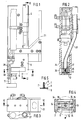
- the bolt setting device shown in the figures consists in both embodiments of an elongated housing 3 with a bolt catcher and a bolt feed channel 37 , which is connected at its end emerging from the housing 3 to a flexible feed hose 4 .
- the adhesive bolt 1 with the plate collar 5 are preceded by means of compressed air into the housing 3 and through the stud feed passage 37 to the collecting device and from there into a located at the end of the supply duct 37 inductor.
- the housing 3 can be connected to a robot arm, not shown, by means of a connecting part 31 .
- the retaining bolts 1 consist of a shaft 7 and a plate collar 5 formed thereon, which is coated on the underside with a dry hotmelt adhesive 6 which can be reactivated by the action of heat.
- the shaft 7 is provided with a coarse thread 8 , which is suitable for fastening holding elements with a suitably designed receiving bore for threaded bolts.
- so-called head bolts or smooth bolts can also be used if the associated fastening elements have corresponding receptacles.
- the plate collar 5 can have any surface geometry which, respectively, for the transport by means of compressed air in the supply hose 4 .
- Bolt feed channel 37 is suitable.
- the transfer plate 9 is rotatably mounted below the bolt feed channel 37 on the housing base 12 and has a collecting station 13 for the bolts 1 which are fed in succession and - offset by 180 ° to this - a removal station 14.
- a dot-dash line Swivel arc ( B ) of the transfer plate 9 adapted opening 35 recessed.
- both stations of the transfer plate 9 there are two opposing clamping jaws 15 which are pressed together by means of springs, for example leaf springs 16 .
- the clamping jaws 15 are provided with inclined insertion surfaces 17 , which strive apart apart from the diameter of the bolt feed channel 37 .
- the clamping jaws 15 are pressed apart by the plate collars 5 when the insertion surfaces 17 slide over them and are brought back into the starting position by the restoring force of the leaf springs 16 , in which the bolt shank 7 is firmly gripped by the clamping jaws 15 and simultaneously centered.
- the transfer plate 9 is driven by a drive shaft 18 from a drive motor 19 installed above in the housing 3 and consisting of a pneumatically actuated swivel cylinder.
- the gripping tongs 10 are located above the removal station 14 and consist of two gripping arms 20 which are pivotably mounted at the lower end of a rectangular hollow profile 21 .
- the rectangular hollow profile 21 is connected to the housing 24 of a short-stroke drive, which in turn is connected to a power piston cylinder 30 which is displaceably guided in the housing 3 .
- a plunger 22 acted upon by the short stroke drive is slidably guided in the rectangular hollow profile 21 and engages with its tip 23 between the extended ends of the gripping arms 20 .
- the gripper arms 20 are held apart by spring force and can be compressed by inserting the plunger 22 by pushing the extended ends apart from the plunger tip 23 . Between the gripping arms 20 there is a so-called calotte 36 , which is supported resiliently in the direction of displacement and which presses on the bolt 1 when the gripping arms 20 have moved towards the bolt shaft 7 .
- the power piston cylinder 30 is coupled via a cross member 32 to a further power piston cylinder 33 , which is installed parallel to the direction of displacement of the power piston cylinder 30 next to the latter in the upper area of the housing 3 .
- This second power piston cylinder 33 is controlled separately from the first power piston cylinder 30 , so that the latter can be moved downward by the stroke H1 from the power piston cylinder 33 (FIG. 7).
- the gripping tongs 10 are displaced by the power piston cylinder 30 by the stroke H2 into the lower setting position 29 via the housing 24 of the short-stroke drive (FIG. 8).
- the inductor 11 is attached to the housing 3 under the housing base 12 in the extension of the removal position 14 of the transfer plate 9 and consists of a cylindrical housing 26 which terminates at the lower end with a collar ring 25 .
- the inside diameter of the housing 26 is somewhat larger than the outside diameter of the collar 5 , so that the pin 1 can be freely inserted into the opening of the inductor 11 by the gripping tongs 10 .
- the housing 26 is penetrated into the collar 25 by a plurality of induction coils 27 , which are supplied with power from the outside via lines 28 .
- the current is switched on via a sensor, not shown.
- a magnetic field is generated, which heats the bolt 1 rapidly and thereby melts the adhesive layer 6 below the plate collar 5 in a very short time.
- a bolt 1 is fed from the feed channel 37 into the receiving position 13 of the transfer plate 9 , the clamping jaws 15 being pressed apart by the collar 5 of the bolt 1 and then springing together again, so that the bolt shaft 7 is held securely by the clamping jaws 15 (FIG. 2) .
- the plate 9 is then pivoted through the opening 35 through 180 ° and the bolt 1 is brought into the removal position 14 .
- the gripping pliers 10 are now lowered by the stroke H1 by actuation of the power piston cylinder 33 (FIG. 7) and the bolt shaft 7 is gripped by the two gripping arms 20 , which are pressed together by the plunger 22 .
- the gripping pliers 10 are lowered by means of the second power piston cylinder 30 in accordance with the stroke H2 until the plate collar 7 of the bolt 1 is on the same with the lower edge of the inductor 11 Height completes.
- the inductor 11 lies with its collar 25 on the support surface 2 .
- the gripper arms 20 are now opened slightly so that the bolt 1 is pressed onto the support surface 2 by means of the spring-supported calotte 23 .
- the induction current is switched on and the magnetic field is activated, which has a frequency range of preferably 10 KHz to 30 MHz.
- the adhesive 6 is melted on the underside of the plate collar 7 , so that it bonds with the surface of the carrier surface 2 .
- the pin 1 is released by the gripping arms 20 and the setting device can be moved into the next joining position 29 by the robot.
- next bolt 1 has already passed through the feed channel 37 into the receiving station 13 of the transfer plate 9 acting as a buffer and can be pivoted into the removal station 14 as soon as the gripping tongs 10 have returned to their starting position (FIG. 6).
- the embodiment of the bolt setting device shown in FIGS. 9-15 can - just like the embodiment described above - be mounted on the arm of a robot (not shown) or can be guided and set by hand.
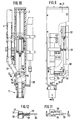
- This embodiment differs from the previously described embodiment according to FIGS. 1-4 essentially by two design changes: firstly, the adhesive bolts 1 are pressed in the joining position 29 by means of a pneumatically driven pressure stamp 38 and secondly the adhesive bolts 1 in the bolt feed channel 37 are now moved by a slide 56 caught.
- the components that have the same design or function in the first embodiment are given the same reference numbers.
- the bolt setting device here also consists of a housing 3 with a bolt feed channel 37, which can be connected at its end projecting from the housing 3 to a flexible feed hose 4 for the provision of the bolts 1 .
- the inductor 11 At the end of the pin feed channel 37 there is also the inductor 11, which is formed from a cylindrical housing 26 which terminates at its lower end with a collar ring 25 .
- An induction coil 27 with two windings is embedded in these, which are supplied with power for rapid heating from the outside via lines 28 .
- the pressure stamp 38 is connected via a stamp rod 39 to a pneumatically actuated pressure cylinder 40 and is displaceably guided in the axial extension of the inductor 11 .
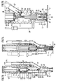
- the pressure cylinder 40 is in turn driven by a likewise pneumatically actuated feed cylinder 42 , which is permanently installed in the housing 3 and moves the pressure stamp 38 from the starting position (FIG. 13) to the joining position (FIGS. 14 and 15).
- the pressure cylinder 38 is connected to the pistons 44 of the feed cylinder 42 via a yoke plate 43 and is displaceably guided on both sides by means of sliding blocks 45 in corresponding grooves 46 in the housing 3 .
- the pressure cylinder 40 is positioned in the axis of movement of the feed cylinder 42 between its yoke plate 43 and the flange 4 + 7 of a punch rod guide 41 and screwed to this flange 47 .
- Flange 47 and yoke plate 43 are also connected to one another by four holding plates 48 .
- the punch rod guide 41 is in its upper starting position outside of the bolt feed channel 37, which opens from the side of the housing 3 below the upper position of the pressure die 38 at an acute angle into the elongated axis of the inductor 11 with an arcuate deflection 49 .
- This deflection 49 is milled in a two-part entry channel 50 in such a way that the adhesive bolts 1 can be easily conveyed into the inductor 11 .
- a guide track 51 is drilled out for the ram guide 41 in the entry channel 50 in the extended axis of the inductor 11 .
- the pressure die 38 screwed onto the die rod 39 has the same outer diameter as the die rod guide 41 .
- the punch 38 also has, on its pressing face a funnel-shaped recess 52 which is intended to press the adhesive bolt 1 via the bolt shaft 7 to the support surface 2 and at the same time to center in the inductor 11 during the adhesive joining process.
- the inductor housing 26 includes a corresponding air outlet at the upper end of the gap 54 a plurality of radially arranged holes 55 which allows the air to escape laterally from the inductor 11 when the adhesive bolt 1 rests during the joining process on the support surface.
- a slide 56 which can be inserted transversely to the axis of the channel 37 is provided in the pin feed channel 37 above the inductor 11 and is equipped with a damping plate 57 on the pin feed side.
- This slide 56 is displaceably guided in a housing 58 which is screwed onto the closed entry channel 50 on the outside.
- the slider 56 is connected at its rear end to a Bowden cable 60 which, as can be seen particularly clearly from FIG. 9, is connected via an abutment 61 to an actuating cylinder 62 permanently installed in the upper housing 3 .
- a Bowden cable 60 which, as can be seen particularly clearly from FIG. 9, is connected via an abutment 61 to an actuating cylinder 62 permanently installed in the upper housing 3 .
- the rear end forms a slide stop 59.
- the slide 56 can in principle be arranged as close to the inductor 11 as the space in the housing 3 allows. However, it is expedient to arrange the slide 56 , as drawn, laterally next to the guideway 51 of the pressure plunger 38 in the bolt feed channel 37 , and as shortly as possible before its deflection 49 . In this case, the slide 56 can already be closed again after the adhesive bolt 1 has continued into the inductor 11 to catch the subsequent bolt 1 , while the preceding bolt 1 still remains in the joining position 29 and is pressed by the punch 38 onto the carrier surface 2 .
- the slide 56 can be used in this way - just like the transfer plate 9 of the embodiment described first - as a buffer (see FIG. 15).
- the bolt setting device of the embodiment shown in FIGS. 9 to 15 works in the following way:
- the adhesive bolt 1 is shot through the feed hose 4 into the bolt feed channel 37 and is braked and caught by the damping plate 57 .
- the slide 56 is opened by means of the actuating cylinder 62 via the Bowden cable 60 and the adhesive bolt 1 flies, driven by the air pressure, through the deflection 49 into the inductor 1 .
- the feed cylinder 42 and the pressure cylinder 40 are simultaneously pressurized with compressed air, while the weft compressed air is briefly switched off.
- the feed cylinder 42 moves the stamp guide 41 into the joining position and the pressure cylinder 40 actuates the pressure stamp 38 via the stamp rod 39 , which, after the induction current has been switched on during the adhesive joining process, transmits the necessary contact pressure to the adhesive bolt 1 .
- the displacement of the pressure cylinder 40 is dimensioned so that the stamp 38 remains in contact with the adhesive bolt 1 despite the reduction in the distance between the plate collar 5 and the support surface 2 while the adhesive layer 6 is melting away.
- the setting device can be moved back from the carrier surface 2 and brought into the next joining position 29 .
Landscapes
- Engineering & Computer Science (AREA)
- Mechanical Engineering (AREA)
- Automatic Assembly (AREA)
- Adhesives Or Adhesive Processes (AREA)
- Lining Or Joining Of Plastics Or The Like (AREA)
- Coating Apparatus (AREA)
- Making Paper Articles (AREA)
- Automobile Manufacture Line, Endless Track Vehicle, Trailer (AREA)
- General Induction Heating (AREA)
- Manipulator (AREA)
Description
- Figur 1
- das Gehäuse einer erfindungsgemäßen Bolzensetzvorrichtung in Seitenansicht,
- Figur 2
- einen Längsschnitt durch das Gehäuse gemäß Linie II - II in Figur 1,
- Figur 3
- das Gehäuse der Bolzensetzvorrichtung in Draufsicht,
- Figur 4
- einen Schnitt durch den Übergabeteller gemäß Linie IV - IV in Figur 1,
- Figur 5
- einen zum Setzen vorgesehenen Gewindebolzen in Seitenansicht
- Figur 6
- einen Längsschnitt durch das Gehäuse gemäß Linie VI - VI in Figur 3 mit Greifzange in Ausgangsposition,
- Figur 7
- den gleichen Längsschnitt wie Figur 6, mit auf Entnahmeposition abgesenkter Greifzange,
- Figur 8
- den gleichen Längsschnitt wie Figur 6, jedoch mit Greifzange in Bolzensetz- bzw. Fügeposition,
- Figur 9
- das Gehäuse einer anderen Ausführungsform der Bolzensetzvorrichtung in Seitenansicht mit teilweisem Einblick auf die Schieberanordnung,
- Figur 10
- einen Längsschnitt durch das Gehäuse gemäß Linie X-X in Figur 9,
- Figur 11
- einen Teilquerschnitt durch das Gehäuse gemäß Linie XI-XI in Figur 9 oder 10 mit Draufsicht auf den geschlossenen Schieber,
- Figur 12
- einen Ausschnitt des Bolzenzuführungskanals mit geschlossenem Schieber im Querschnitt gemäß Linie XII-XII in Figur 11,
- Figur 13
- einen Längsschnitt durch das Gehäuse der Bolzensetzvorrichtung mit Stempel in Ausgangsposition,
- Figur 14
- den gleichen Längsschnitt durch das Gehäuse mit Stempel in Fügeposition und
- Figur 15
- einen vergrößerten Ausschnitt des unteren Setzbereichs in Fügeposition.
Der Übergabeteller 9 ist unterhalb des Bolzenzuführungskanals 37 auf dem Gehäuse-boden 12 drehbar gelagert und besitzt eine Auffangstation 13 für die nacheinander zugeführten Bolzen 1 und - um 180° versetzt dazu - eine Entnahmestation 14. In der Längswand 34 des Gehäuses 3 ist eine dem strichpunktierten Schwenkbogen ( B ) des Übergabetellers 9 angepaßte Öffnung 35 ausgespart.
Claims (11)
- Vorrichtung zum automatisierten Setzen und Aufkleben von Haltebolzen auf Trägerflächen, wobei die Haltebolzen ( 1 ) mit Tellerbünden ( 5 ) versehen sind, welche an ihrer Unterseite mit einem trockenen, durch Wärmeeinwirkung reaktivierbaren Schmelzklebstoff ( 6 ) beschichtet sind; unter Verwendung eines länglichen Gehäuses ( 3 ) mit einer Bolzenauffangvorrichtung und einem Bolzenzuführungskanal ( 37) , welcher an seinem aus dem Gehäuse ( 3 ) vorstehenden Ende mit einem flexiblen Zuführschlauch ( 4 ) verbindbar ist, durch welchen die Haltebolzen ( 1 ) mittels Druckluft in das Gehäuse ( 3 ) und durch den Bolzenzuführungskanal ( 37 ) bis zur Auffangvorrichtung förderbar sind, dadurch gekennzeichnet, daß sich am Ende des Bolzenzuführungskanals (37) ein mit einer Induktionsspule versehener Zylinder (11) - nachfolgend Induktor genannt - befindet, in welchen der Haltebolzen ( 1 ) mit dem Tellerbund ( 5 ) voraus einführbar ist, wobei oberhalb des Induktors ( 11 ) Mittel zum Andrücken des im Induktor ( 11 ) befindlichen Haltebolzens ( 1 ) auf die Fügeposition der Trägerfläche ( 2 ) vorgesehen sind.
- Bolzensetzvorrichtung nach Anspruch 1 unter Verwendung einer Greifzange ( 10 ) zum Erfassen des Bolzenschaftes ( 7 ) und Andrücken des Bolzens (1) auf die vorgesehene Fügeposition ( 29 ) der Trägerfläche ( 2 ) dadurch gekennzeichnet, daß im Gehäuse ( 3 ) unterhalb des Bolzenzuführungskanals ( 4) ein Übergabeteller ( 9 ) drehbar gelagert ist, welcher mit einer Auffangtation (13) für die einzelnd zugeführten Bolzen ( 1 ) und einer um 180° versetzten Entnahmestation ( 14 ) versehen ist, wobei die verschieblich geführte Greifzange ( 10 ) oberhalb und der Induktor ( 11 ) unterhalb der Entnahmestation ( 14 ) angeordnet sind.
- Bolzensetzvorrichtung nach Anspruch 2, dadurch gekennzeichnet, daß der Tellerbund ( 5 ) des Bolzens ( 1 ) in der untersten Haltestellung mit dem unteren Rand des Induktors (11) auf gleicher Höhe abschließt.
- Bolzensetzvorrichtung nach Anspruch 2 oder 3, dadurch gekennzeichnet, daß zwischen den Greifarmen ( 20 ) der Greifzange ( 10 ) eine in Andrückrichtung federnd abgestützte Kalotte ( 36 ) gelagert ist, welche bei Erreichen der Fügeposition auf den Bolzen ( 1 ) einwirkt und diesen mit konstanter Kraft auf die Trägerfläche ( 2) drückt.
- Bolzensetzvorrichtung nach einem der Ansprüche 2 bis 4, dadurch gekennzeichnet, daß die Greifzange ( 10 ) von zwei miteinander gekoppelten Kraftkolbenzylindern ( 30 ) und (33) betätigt wird, wobei der eine Kraftkolbenzylinder ( 33 ) die Bewegung der Greifzange ( 10 ) von der Ruhestellung in die erste Greifposition zum Erfassen des Bolzenschaftes ( 7 ) steuert und der andere Kraftkolbenzylinder ( 30 ) den von den Greifarmen ( 20) erfaßten Haltebolzen ( 1 ) in die Fügeposition ( 29) auf der Trägerfläche (2) bewegt.
- Bolzensetzvorrichtung nach einem der Ansprüche 2 bis 5, dadurch gekennzeichnet,daß im Übergabeteller ( 9 ) in den Endpositionen je zwei gegenüberliegende Klemmbacken ( 15 ) auffederbar gelagert sind, welche in Zuführrichtung der Haltebolzen ( 1) mit schrägen Einlaufflächen ( 17) versehen sind.
- Bolzensetzvorrichtung nach Anspruch 1, dadurch gekennzeichnet, daß zum Andrücken der Haltebolzen ( 1 ) auf die Trägerfläche ( 2 ) ein pneumatisch beaufschlagter Anpreßstempel ( 38) vorgesehen ist, welcher in axialer Verlängerung des Induktors ( 11 ) im Gehäuse ( 3 ) verschieblich geführt ist, wobei der Bolzenzuführungskanal ( 37 ) von einer Seite des Gehäuses ( 3 ) aus unterhalb der oberen Lage des Anpreßstempels ( 38 ) unter einem spitzen Winkel in die verlängerte Achse des Induktors (11) einmündet.
- Bolzensetzvorrichtung nach Anspruch 7, dadurch gekennzeichnet, daß der Anpreßstempel ( 38 ) über eine Stempelstange ( 39 ) mit einem pneumatisch beaufschlagten Anpreßzylinder ( 40 ) verbunden ist, der wiederum von einem pneumatisch beaufschlagten Vorschubzylinder ( 42 ) getrieben wird, welcher den Anpreßstempel ( 38) von der Ausgangsposition in die Fügeposition fährt.
- Bolzensetzvorrichtung nach einem der Ansprüche 7 oder 8, dadurch gekennzeichnet, daß zum Auffangen der zugeführten Haltebolzen ( 1 ) im Bolzenzuführungskanal ( 37 ) oberhalb des Induktors ( 11 ) ein quer zur Achse des Kanals ( 37 ) einführbarer Schieber ( 56 ) vorgesehen ist, welcher auf der Bolzenzuführseite mit einer Dämpfungsplatte ( 57 ) bestückt ist.
- Bolzensetzvorrichtung nach Anspruch 9, dadurch gekennzeichnet, daß der Schieber ( 56 ) seitlich neben der Führungsbahn ( 51 ) des Anpreßstempels ( 38 ) im Bolzenzuführungskanal ( 37 ) angeordnet ist.
- Arbeitsverfahren zum automatisierten Setzen von Halte- oder Befestigungsbolzen unter Verwendung einer Vorrichtung nach Anspruch 1,
gekennzeichnet durch folgende Verfahrensschritte:Heranführen der vereinzelten Bolzen mittels DruckluftAuffangen und Weiterleiten in eine von einem induzierenden Magnetfeld umgebenen Fügeposition,Halten des Bolzens in der Fügeposition,Aktivierung des Magnetfeldes unter gleichzeitigem Andrücken des Tellerbundes auf die Trägerfläche undFreigabe des Bolzens nach Erreichen der für die weitere Verarbeitung erforderlichen Mindesthaftfestigkeit.
Applications Claiming Priority (3)
| Application Number | Priority Date | Filing Date | Title |
|---|---|---|---|
| DE19638521A DE19638521C2 (de) | 1996-09-20 | 1996-09-20 | Vorrichtung zum automatisierten Setzen von Haltebolzen auf Trägerflächen |
| DE19638521 | 1996-09-20 | ||
| PCT/EP1997/005052 WO1998012016A1 (de) | 1996-09-20 | 1997-09-16 | Vorrichtung zum automatisierten setzen von haltebolzen auf trägerflächen |
Publications (2)
| Publication Number | Publication Date |
|---|---|
| EP0927091A1 EP0927091A1 (de) | 1999-07-07 |
| EP0927091B1 true EP0927091B1 (de) | 2000-11-08 |
Family
ID=7806306
Family Applications (1)
| Application Number | Title | Priority Date | Filing Date |
|---|---|---|---|
| EP97909272A Expired - Lifetime EP0927091B1 (de) | 1996-09-20 | 1997-09-16 | Vorrichtung zum automatisierten setzen von haltebolzen auf trägerflächen |
Country Status (13)
| Country | Link |
|---|---|
| US (1) | US6221195B1 (de) |
| EP (1) | EP0927091B1 (de) |
| JP (1) | JP2001500797A (de) |
| KR (1) | KR100570519B1 (de) |
| CN (1) | CN1104994C (de) |
| AT (1) | ATE197420T1 (de) |
| BR (1) | BR9712836A (de) |
| CZ (1) | CZ291169B6 (de) |
| DE (1) | DE19638521C2 (de) |
| ES (1) | ES2153653T3 (de) |
| HU (1) | HU222106B1 (de) |
| PT (1) | PT927091E (de) |
| WO (1) | WO1998012016A1 (de) |
Cited By (1)
| Publication number | Priority date | Publication date | Assignee | Title |
|---|---|---|---|---|
| DE102007000862A1 (de) * | 2007-10-12 | 2009-04-23 | Airbus Deutschland Gmbh | Verfahren zum Verbinden eines ersten Materials mit einem zweiten Material im Flugzeug |
Families Citing this family (20)
| Publication number | Priority date | Publication date | Assignee | Title |
|---|---|---|---|---|
| DE19916984C1 (de) * | 1999-04-15 | 2000-07-13 | Raymond A & Cie | Steckverbindung für wassergekühlte, stromführende Leitungen an Werkzeugen und anderen Geräten |
| DE10000355A1 (de) * | 2000-01-07 | 2001-07-26 | Raymond A & Cie | Vorrichtung zum Setzen und Ankleben von Halteelementen auf Trägerflächen |
| DE102004012786A1 (de) * | 2004-03-15 | 2005-09-29 | Newfrey Llc, Newark | Fügevorrichtung zum Befestigen von kleinteiligen Bauelementen an einer Trägerfläche durch Kleben |
| DE102006038624A1 (de) | 2006-08-17 | 2008-03-06 | Tesa Ag | Verfahren zur Fixierung eines Bauteils auf einem zu lackierenden Fügepartner |
| DE102009042467A1 (de) * | 2009-09-23 | 2011-03-24 | Audi Ag | Fügeverfahren, Fügevorrichtung und Befestigungselement |
| DE102009057332B4 (de) | 2009-12-07 | 2020-03-26 | Böllhoff Verbindungstechnik GmbH | Manuelle und automatische Befestigungsvorrichtung eines Klebeelements sowie Verfahren dafür |
| DE102011009259A1 (de) | 2011-01-24 | 2012-07-26 | Böllhoff Verbindungstechnik GmbH | Fügekopf zum Befestigen eines Befestigungselements sowie ein Befestigungsverfahren |
| ES2656054T3 (es) * | 2011-07-05 | 2018-02-22 | Conceptromec Inc. | Sistema de separación de clip, kit para ensamble del mismo |
| DE102011080137A1 (de) * | 2011-07-29 | 2013-01-31 | Siemens Aktiengesellschaft | Sortieranlage und Sortierverfahren mit einem Greifwerkzeug |
| CN103737297A (zh) * | 2013-12-26 | 2014-04-23 | 镇江晶鑫电子科技有限公司 | 一种光栅自动定位装配装置 |
| DE102014226148A1 (de) * | 2014-12-17 | 2016-06-23 | Bayerische Motoren Werke Aktiengesellschaft | Kleben von Klebebolzen |
| EP3330334A1 (de) | 2016-11-30 | 2018-06-06 | Newfrey LLC | Fügeverfahren und befestigungselement |
| CN107962370B (zh) * | 2017-12-11 | 2019-07-02 | 安徽益必生物科技有限公司 | 用于医疗机械生产的插接装置 |
| CN109317957B (zh) * | 2018-10-19 | 2023-12-19 | 盐城国投中科新能源科技有限公司 | 一种用于塑料螺栓机器人 |
| CN112276204B (zh) * | 2020-10-26 | 2023-01-24 | 震宇(芜湖)实业有限公司 | 一种汽车排气管用连续切割设备 |
| CN113048129B (zh) * | 2021-03-15 | 2022-12-06 | 长沙航顺公共设备有限公司 | 一种灯具加工用灯具粘合设备 |
| CN116408619A (zh) * | 2021-12-30 | 2023-07-11 | 沈阳新松机器人自动化股份有限公司 | 一种小型大长径比工件自对中定位装置 |
| CN115816048B (zh) * | 2023-02-27 | 2023-05-23 | 宁波市全盛壳体有限公司 | 一种螺丝自动组装机构及组装设备 |
| DE102023002808B3 (de) | 2023-07-10 | 2024-11-07 | Mercedes-Benz Group AG | Zweiteiliges Werkzeug für Roboterschraubeinheit |
| CN119217037B (zh) * | 2024-12-05 | 2025-02-07 | 科讯工业制造(深圳)有限公司 | 一种螺丝锁付机构及自动锁螺丝机 |
Family Cites Families (23)
| Publication number | Priority date | Publication date | Assignee | Title |
|---|---|---|---|---|
| DE7044506U (de) * | 1971-03-04 | Breschinsky R | Gerat zum Eintreiben von Ver bindungs oder Befestigungselementen | |
| US3563361A (en) * | 1968-06-04 | 1971-02-16 | Self Matic Valves Corp | Setscrew feeding, orienting and driving system |
| DE1925766B2 (de) * | 1969-05-21 | 1971-07-22 | Metallischer gewindeeinsatz zum waermedruckeinbau in kalte werkstuecke aus thermoplastischem kunststoff zweckmaessiges verfahren zum eindruecken des gewindeeinsatzes und vor richtung zur durchfuehrung des verfahrens | |
| NL7208789A (de) * | 1971-07-05 | 1973-01-09 | ||
| DE2230412A1 (de) * | 1972-06-22 | 1974-01-10 | Boellhoff & Co | Verfahren zum waermedruckeinbau von befestigungselementen in kalte werkstuecke aus thermoplastischem kunststoff und vorrichtung zur durchfuehrung des verfahrens |
| GB1513052A (en) * | 1976-04-02 | 1978-06-07 | Psm Fasteners Ltd | Installing inserts |
| US4128449A (en) * | 1977-09-28 | 1978-12-05 | Illinois Tool Works Inc. | Induction heating fixture for applying adhesive-backed articles |
| US4139408A (en) * | 1977-09-28 | 1979-02-13 | Illinois Tool Works Inc. | Adhesive fastener article |
| US4163884A (en) * | 1977-09-28 | 1979-08-07 | Illinois Tool Works Inc. | Induction heating core for adhesive fastening systems |
| DE2938897A1 (de) * | 1979-09-26 | 1981-04-02 | Franz 5427 Bad Ems Fischbach | Nagelgeraet |
| US4355222A (en) * | 1981-05-08 | 1982-10-19 | The Boeing Company | Induction heater and apparatus for use with stud mounted hot melt fasteners |
| FR2549408B1 (fr) * | 1983-07-22 | 1985-10-18 | Citroen Sa | Poignet de robot pour la distribution et l'embectage de vis |
| US4478669A (en) * | 1984-02-27 | 1984-10-23 | Illinois Tool Works Inc. | Adhesive bonded gun assembly for applying fastener |
| US4602537A (en) * | 1985-05-15 | 1986-07-29 | Dixon Automatic Tool, Inc. | Automatic assembly machine |
| US4822656A (en) * | 1985-09-04 | 1989-04-18 | Physical Systems, Inc. | Fixture for securing an adhesive attachment to a substrate |
| DE3717959A1 (de) * | 1987-05-27 | 1988-12-08 | Itw Ateco Gmbh | Vorsatzgeraet zum eindrehen von schrauben mit hilfe eines kraftgetriebenen schraubers |
| US4853075A (en) * | 1987-11-05 | 1989-08-01 | Chrysler Motors Corporation | Apparatus for automated assembly of a harness retainer stud |
| US4872603A (en) * | 1988-09-16 | 1989-10-10 | Spirol International Corporation | Insert installation machine |
| DE69209326T2 (de) * | 1991-01-12 | 1996-10-31 | Yoshitaka Aoyama | Zuführeinrichtung für Teile |
| JPH05208328A (ja) * | 1992-01-28 | 1993-08-20 | Aoyama Seisakusho:Kk | ナット類の供給装置 |
| US5414247A (en) * | 1993-12-29 | 1995-05-09 | The Boeing Company | Hot melt induction heater and method |
| DE4402550A1 (de) * | 1994-01-28 | 1995-08-03 | Raymond A Gmbh & Co Kg | Verklebbares Befestigungselement zum Halten von Bau- oder Funktionsteilen auf Trägerteilen |
| DE19645000B4 (de) * | 1996-10-30 | 2005-04-07 | A. Raymond & Cie | Verfahren zum Beschichten der Klebeflächen von Befestigungselementen mit Schmelzklebstoffen |
-
1996
- 1996-09-20 DE DE19638521A patent/DE19638521C2/de not_active Expired - Fee Related
-
1997
- 1997-09-16 ES ES97909272T patent/ES2153653T3/es not_active Expired - Lifetime
- 1997-09-16 HU HU0000662A patent/HU222106B1/hu not_active IP Right Cessation
- 1997-09-16 JP JP10514276A patent/JP2001500797A/ja active Pending
- 1997-09-16 PT PT97909272T patent/PT927091E/pt unknown
- 1997-09-16 AT AT97909272T patent/ATE197420T1/de not_active IP Right Cessation
- 1997-09-16 BR BR9712836-8A patent/BR9712836A/pt not_active IP Right Cessation
- 1997-09-16 WO PCT/EP1997/005052 patent/WO1998012016A1/de not_active Ceased
- 1997-09-16 KR KR1019997002075A patent/KR100570519B1/ko not_active Expired - Fee Related
- 1997-09-16 EP EP97909272A patent/EP0927091B1/de not_active Expired - Lifetime
- 1997-09-16 US US09/269,610 patent/US6221195B1/en not_active Expired - Fee Related
- 1997-09-16 CN CN97198102A patent/CN1104994C/zh not_active Expired - Fee Related
- 1997-09-16 CZ CZ1999994A patent/CZ291169B6/cs not_active IP Right Cessation
Cited By (1)
| Publication number | Priority date | Publication date | Assignee | Title |
|---|---|---|---|---|
| DE102007000862A1 (de) * | 2007-10-12 | 2009-04-23 | Airbus Deutschland Gmbh | Verfahren zum Verbinden eines ersten Materials mit einem zweiten Material im Flugzeug |
Also Published As
| Publication number | Publication date |
|---|---|
| HU222106B1 (hu) | 2003-04-28 |
| ATE197420T1 (de) | 2000-11-11 |
| HUP0000662A3 (en) | 2001-02-28 |
| CN1104994C (zh) | 2003-04-09 |
| CN1230911A (zh) | 1999-10-06 |
| JP2001500797A (ja) | 2001-01-23 |
| KR100570519B1 (ko) | 2006-04-12 |
| DE19638521C2 (de) | 1998-07-30 |
| CZ99499A3 (cs) | 1999-12-15 |
| HUP0000662A2 (hu) | 2000-12-28 |
| PT927091E (pt) | 2001-04-30 |
| WO1998012016A1 (de) | 1998-03-26 |
| KR20010029501A (ko) | 2001-04-06 |
| EP0927091A1 (de) | 1999-07-07 |
| WO1998012016A8 (de) | 2001-04-12 |
| DE19638521A1 (de) | 1998-03-26 |
| ES2153653T3 (es) | 2001-03-01 |
| CZ291169B6 (cs) | 2003-01-15 |
| BR9712836A (pt) | 1999-11-16 |
| US6221195B1 (en) | 2001-04-24 |
Similar Documents
| Publication | Publication Date | Title |
|---|---|---|
| EP0927091A1 (de) | Vorrichtung zum automatisierten setzen von haltebolzen auf trägerflächen | |
| DE102004012786A1 (de) | Fügevorrichtung zum Befestigen von kleinteiligen Bauelementen an einer Trägerfläche durch Kleben | |
| EP2167283B1 (de) | Zuführeinrichtung, setzgerät und verfahren zum zuführen und fügen von befestigungselementen | |
| WO1996001161A1 (de) | Nietenzuführung | |
| DE1627858A1 (de) | Automatisierte Presse | |
| DE69918241T2 (de) | Verstellbare Vorrichtung zum Zuführen von Nieten an einem Nietwerkzeug | |
| DE4244403A1 (de) | Automatische Nietmaschine | |
| DE102017212660A1 (de) | Saugvorrichtung | |
| EP1250391A1 (de) | Vorrichtung zum setzen und ankleben von halteelementen auf trägerflächen | |
| DE4101545C2 (de) | ||
| DE69913913T2 (de) | Nietwerkzeug mit luftunterstütztem Schnellruckhub | |
| DE102014221139A1 (de) | Kunststoff-Vorwärmanordnung für eine Kunststoffschweißvorrichtung, Kunststoffschweißvorrichtung sowie Vorwärmverfahren für ein Bauteil | |
| DE19731344B4 (de) | System zum Zuführen von Verbindungselementen an einen Stanzkopf | |
| EP0030353B1 (de) | Verfahren und Vorrichtung zum Herstellen von Einmalkanülen | |
| DE2233412A1 (de) | Verfahren und vorrichtung zum befestigen von gegenstaenden auf einer unterlage durch klebung | |
| DE4331783A1 (de) | Maschine zum Ansetzen von Knöpfen, Nieten oder dergleichen, vorzugsweise an Bekleidungsstücke | |
| DE1925766A1 (de) | Verfahren zum Einbau von metallischen Gewindeeinsaetzen in kalte Werkstuecke aus thermoplastischem Kunststoff,ein fuer solches Verfahren geeigneter Gewindeeinsatz und eine Vorrichtung zur Durchfuehrung des Verfahrens | |
| DE3508354C2 (de) | Maschine zum Aufquetschbestücken von Kabeladerenden mit Aderendhülsen od.dgl. Anschlußelementen | |
| EP0725702A1 (de) | Vorrichtung zur verwendung in einer presse zum zuführen von verbindungselementen und deren befestigung in werkstücken durch verpressen | |
| DE4429737A1 (de) | Setzkopf und Verfahren zum Betrieb desselben | |
| DE3235547A1 (de) | Verfahren und vorrichtungen zum festen verbinden von bau- bzw. konstruktionselementen | |
| DE4427370C1 (de) | Vorrichtung zum Anschweißen von Metallbolzen an einem Werkstück | |
| DE2434751C3 (de) | Eintreibvorrichtung für mit einer thermoplastischen Oberflächenschicht versehene Dübel | |
| DE2740220A1 (de) | Vorrichtung zum ausrichten von flaschen o.dgl., insbesondere vor dem etikettieren | |
| DE19627573A1 (de) | Vorrichtung zum Herstellen einer Nietverbindung |
Legal Events
| Date | Code | Title | Description |
|---|---|---|---|
| PUAI | Public reference made under article 153(3) epc to a published international application that has entered the european phase |
Free format text: ORIGINAL CODE: 0009012 |
|
| 17P | Request for examination filed |
Effective date: 19990420 |
|
| AK | Designated contracting states |
Kind code of ref document: A1 Designated state(s): AT BE ES FR GB IT NL PT SE |
|
| GRAG | Despatch of communication of intention to grant |
Free format text: ORIGINAL CODE: EPIDOS AGRA |
|
| 17Q | First examination report despatched |
Effective date: 19991123 |
|
| RBV | Designated contracting states (corrected) |
Designated state(s): AT BE ES FR GB IT NL PT SE |
|
| GRAG | Despatch of communication of intention to grant |
Free format text: ORIGINAL CODE: EPIDOS AGRA |
|
| GRAH | Despatch of communication of intention to grant a patent |
Free format text: ORIGINAL CODE: EPIDOS IGRA |
|
| GRAH | Despatch of communication of intention to grant a patent |
Free format text: ORIGINAL CODE: EPIDOS IGRA |
|
| GRAA | (expected) grant |
Free format text: ORIGINAL CODE: 0009210 |
|
| AK | Designated contracting states |
Kind code of ref document: B1 Designated state(s): AT BE ES FR GB IT NL PT SE |
|
| REF | Corresponds to: |
Ref document number: 197420 Country of ref document: AT Date of ref document: 20001111 Kind code of ref document: T |
|
| ET | Fr: translation filed | ||
| GBT | Gb: translation of ep patent filed (gb section 77(6)(a)/1977) |
Effective date: 20010109 |
|
| ITF | It: translation for a ep patent filed | ||
| REG | Reference to a national code |
Ref country code: ES Ref legal event code: FG2A Ref document number: 2153653 Country of ref document: ES Kind code of ref document: T3 |
|
| REG | Reference to a national code |
Ref country code: PT Ref legal event code: SC4A Free format text: AVAILABILITY OF NATIONAL TRANSLATION Effective date: 20010208 |
|
| PLBE | No opposition filed within time limit |
Free format text: ORIGINAL CODE: 0009261 |
|
| STAA | Information on the status of an ep patent application or granted ep patent |
Free format text: STATUS: NO OPPOSITION FILED WITHIN TIME LIMIT |
|
| 26N | No opposition filed | ||
| REG | Reference to a national code |
Ref country code: GB Ref legal event code: IF02 |
|
| PGFP | Annual fee paid to national office [announced via postgrant information from national office to epo] |
Ref country code: PT Payment date: 20050830 Year of fee payment: 9 |
|
| PGFP | Annual fee paid to national office [announced via postgrant information from national office to epo] |
Ref country code: ES Payment date: 20060829 Year of fee payment: 10 |
|
| PGFP | Annual fee paid to national office [announced via postgrant information from national office to epo] |
Ref country code: BE Payment date: 20060920 Year of fee payment: 10 |
|
| PGFP | Annual fee paid to national office [announced via postgrant information from national office to epo] |
Ref country code: AT Payment date: 20060921 Year of fee payment: 10 |
|
| PGFP | Annual fee paid to national office [announced via postgrant information from national office to epo] |
Ref country code: IT Payment date: 20060930 Year of fee payment: 10 |
|
| PG25 | Lapsed in a contracting state [announced via postgrant information from national office to epo] |
Ref country code: PT Free format text: LAPSE BECAUSE OF NON-PAYMENT OF DUE FEES Effective date: 20070316 |
|
| REG | Reference to a national code |
Ref country code: PT Ref legal event code: MM4A Free format text: LAPSE DUE TO NON-PAYMENT OF FEES Effective date: 20070316 |
|
| PGFP | Annual fee paid to national office [announced via postgrant information from national office to epo] |
Ref country code: SE Payment date: 20060918 Year of fee payment: 10 |
|
| BERE | Be: lapsed |
Owner name: A. *RAYMOND & CIE Effective date: 20070930 |
|
| PG25 | Lapsed in a contracting state [announced via postgrant information from national office to epo] |
Ref country code: SE Free format text: LAPSE BECAUSE OF NON-PAYMENT OF DUE FEES Effective date: 20070917 |
|
| EUG | Se: european patent has lapsed | ||
| PG25 | Lapsed in a contracting state [announced via postgrant information from national office to epo] |
Ref country code: AT Free format text: LAPSE BECAUSE OF NON-PAYMENT OF DUE FEES Effective date: 20070916 |
|
| PG25 | Lapsed in a contracting state [announced via postgrant information from national office to epo] |
Ref country code: BE Free format text: LAPSE BECAUSE OF NON-PAYMENT OF DUE FEES Effective date: 20070930 |
|
| PGFP | Annual fee paid to national office [announced via postgrant information from national office to epo] |
Ref country code: NL Payment date: 20080915 Year of fee payment: 12 Ref country code: FR Payment date: 20080915 Year of fee payment: 12 |
|
| REG | Reference to a national code |
Ref country code: ES Ref legal event code: FD2A Effective date: 20070917 |
|
| PGFP | Annual fee paid to national office [announced via postgrant information from national office to epo] |
Ref country code: GB Payment date: 20080917 Year of fee payment: 12 |
|
| PG25 | Lapsed in a contracting state [announced via postgrant information from national office to epo] |
Ref country code: ES Free format text: LAPSE BECAUSE OF NON-PAYMENT OF DUE FEES Effective date: 20070917 |
|
| PG25 | Lapsed in a contracting state [announced via postgrant information from national office to epo] |
Ref country code: IT Free format text: LAPSE BECAUSE OF NON-PAYMENT OF DUE FEES Effective date: 20070916 |
|
| REG | Reference to a national code |
Ref country code: NL Ref legal event code: V1 Effective date: 20100401 |
|
| GBPC | Gb: european patent ceased through non-payment of renewal fee |
Effective date: 20090916 |
|
| REG | Reference to a national code |
Ref country code: FR Ref legal event code: ST Effective date: 20100531 |
|
| PG25 | Lapsed in a contracting state [announced via postgrant information from national office to epo] |
Ref country code: NL Free format text: LAPSE BECAUSE OF NON-PAYMENT OF DUE FEES Effective date: 20100401 Ref country code: FR Free format text: LAPSE BECAUSE OF NON-PAYMENT OF DUE FEES Effective date: 20090930 |
|
| PG25 | Lapsed in a contracting state [announced via postgrant information from national office to epo] |
Ref country code: GB Free format text: LAPSE BECAUSE OF NON-PAYMENT OF DUE FEES Effective date: 20090916 |