EP0925611B1 - Current interrupter for electrochemical cells - Google Patents
Current interrupter for electrochemical cells Download PDFInfo
- Publication number
- EP0925611B1 EP0925611B1 EP97920291A EP97920291A EP0925611B1 EP 0925611 B1 EP0925611 B1 EP 0925611B1 EP 97920291 A EP97920291 A EP 97920291A EP 97920291 A EP97920291 A EP 97920291A EP 0925611 B1 EP0925611 B1 EP 0925611B1
- Authority
- EP
- European Patent Office
- Prior art keywords
- end cap
- cap assembly
- cell
- plate
- diaphragm
- Prior art date
- Legal status (The legal status is an assumption and is not a legal conclusion. Google has not performed a legal analysis and makes no representation as to the accuracy of the status listed.)
- Expired - Lifetime
Links
- 230000037361 pathway Effects 0.000 claims abstract description 22
- 239000000463 material Substances 0.000 claims abstract description 14
- 239000000155 melt Substances 0.000 claims abstract description 4
- 230000002093 peripheral effect Effects 0.000 claims description 12
- 238000002788 crimping Methods 0.000 claims description 5
- 230000009471 action Effects 0.000 claims description 4
- 238000003466 welding Methods 0.000 claims description 4
- 230000006835 compression Effects 0.000 claims 1
- 238000007906 compression Methods 0.000 claims 1
- 230000007246 mechanism Effects 0.000 abstract description 24
- 239000012212 insulator Substances 0.000 description 20
- PXHVJJICTQNCMI-UHFFFAOYSA-N nickel Substances [Ni] PXHVJJICTQNCMI-UHFFFAOYSA-N 0.000 description 13
- 239000008188 pellet Substances 0.000 description 9
- 229910052751 metal Inorganic materials 0.000 description 8
- 239000002184 metal Substances 0.000 description 8
- 229910052759 nickel Inorganic materials 0.000 description 7
- 229910001220 stainless steel Inorganic materials 0.000 description 7
- 239000010935 stainless steel Substances 0.000 description 7
- 229910052782 aluminium Inorganic materials 0.000 description 6
- XAGFODPZIPBFFR-UHFFFAOYSA-N aluminium Chemical compound [Al] XAGFODPZIPBFFR-UHFFFAOYSA-N 0.000 description 6
- 239000003792 electrolyte Substances 0.000 description 6
- 229910001416 lithium ion Inorganic materials 0.000 description 6
- HBBGRARXTFLTSG-UHFFFAOYSA-N Lithium ion Chemical compound [Li+] HBBGRARXTFLTSG-UHFFFAOYSA-N 0.000 description 5
- 229910000831 Steel Inorganic materials 0.000 description 5
- 238000013461 design Methods 0.000 description 5
- 239000010959 steel Substances 0.000 description 5
- 230000000694 effects Effects 0.000 description 4
- PCHJSUWPFVWCPO-UHFFFAOYSA-N gold Chemical compound [Au] PCHJSUWPFVWCPO-UHFFFAOYSA-N 0.000 description 4
- 229910052737 gold Inorganic materials 0.000 description 4
- 239000010931 gold Substances 0.000 description 4
- 238000010438 heat treatment Methods 0.000 description 4
- -1 nickel metal hydride Chemical class 0.000 description 4
- 229910052709 silver Inorganic materials 0.000 description 4
- 239000004332 silver Substances 0.000 description 4
- 229910000881 Cu alloy Inorganic materials 0.000 description 3
- DMFGNRRURHSENX-UHFFFAOYSA-N beryllium copper Chemical compound [Be].[Cu] DMFGNRRURHSENX-UHFFFAOYSA-N 0.000 description 3
- YOCUPQPZWBBYIX-UHFFFAOYSA-N copper nickel Chemical compound [Ni].[Cu] YOCUPQPZWBBYIX-UHFFFAOYSA-N 0.000 description 3
- 230000007797 corrosion Effects 0.000 description 3
- 238000005260 corrosion Methods 0.000 description 3
- 229920003023 plastic Polymers 0.000 description 3
- SYJPAKDNFZLSMV-HYXAFXHYSA-N (Z)-2-methylpropanal oxime Chemical compound CC(C)\C=N/O SYJPAKDNFZLSMV-HYXAFXHYSA-N 0.000 description 2
- KMTRUDSVKNLOMY-UHFFFAOYSA-N Ethylene carbonate Chemical compound O=C1OCCO1 KMTRUDSVKNLOMY-UHFFFAOYSA-N 0.000 description 2
- WHXSMMKQMYFTQS-UHFFFAOYSA-N Lithium Chemical compound [Li] WHXSMMKQMYFTQS-UHFFFAOYSA-N 0.000 description 2
- 239000004698 Polyethylene Substances 0.000 description 2
- 230000004913 activation Effects 0.000 description 2
- 239000011149 active material Substances 0.000 description 2
- OJIJEKBXJYRIBZ-UHFFFAOYSA-N cadmium nickel Chemical compound [Ni].[Cd] OJIJEKBXJYRIBZ-UHFFFAOYSA-N 0.000 description 2
- 239000010960 cold rolled steel Substances 0.000 description 2
- 238000007599 discharging Methods 0.000 description 2
- 229910052744 lithium Inorganic materials 0.000 description 2
- 230000008018 melting Effects 0.000 description 2
- 238000002844 melting Methods 0.000 description 2
- 229910052987 metal hydride Inorganic materials 0.000 description 2
- 239000000203 mixture Substances 0.000 description 2
- 238000013021 overheating Methods 0.000 description 2
- 239000004033 plastic Substances 0.000 description 2
- 229920000728 polyester Polymers 0.000 description 2
- 229920000573 polyethylene Polymers 0.000 description 2
- RUOJZAUFBMNUDX-UHFFFAOYSA-N propylene carbonate Chemical compound CC1COC(=O)O1 RUOJZAUFBMNUDX-UHFFFAOYSA-N 0.000 description 2
- 238000000926 separation method Methods 0.000 description 2
- 239000002904 solvent Substances 0.000 description 2
- 239000012815 thermoplastic material Substances 0.000 description 2
- 238000013022 venting Methods 0.000 description 2
- OKTJSMMVPCPJKN-UHFFFAOYSA-N Carbon Chemical compound [C] OKTJSMMVPCPJKN-UHFFFAOYSA-N 0.000 description 1
- 229920013683 Celanese Polymers 0.000 description 1
- 229910000640 Fe alloy Inorganic materials 0.000 description 1
- 229910001030 Iron–nickel alloy Inorganic materials 0.000 description 1
- 229910001290 LiPF6 Inorganic materials 0.000 description 1
- 229920000106 Liquid crystal polymer Polymers 0.000 description 1
- 239000004977 Liquid-crystal polymers (LCPs) Substances 0.000 description 1
- 229910001091 LixCoO2 Inorganic materials 0.000 description 1
- 239000004677 Nylon Substances 0.000 description 1
- 239000004642 Polyimide Substances 0.000 description 1
- 239000004743 Polypropylene Substances 0.000 description 1
- 229910045601 alloy Inorganic materials 0.000 description 1
- 239000000956 alloy Substances 0.000 description 1
- 239000006183 anode active material Substances 0.000 description 1
- 239000010405 anode material Substances 0.000 description 1
- 239000003125 aqueous solvent Substances 0.000 description 1
- 230000008901 benefit Effects 0.000 description 1
- HJJVPARKXDDIQD-UHFFFAOYSA-N bromuconazole Chemical compound ClC1=CC(Cl)=CC=C1C1(CN2N=CN=C2)OCC(Br)C1 HJJVPARKXDDIQD-UHFFFAOYSA-N 0.000 description 1
- 229910052799 carbon Inorganic materials 0.000 description 1
- 239000006182 cathode active material Substances 0.000 description 1
- 239000010406 cathode material Substances 0.000 description 1
- BIJOYKCOMBZXAE-UHFFFAOYSA-N chromium iron nickel Chemical compound [Cr].[Fe].[Ni] BIJOYKCOMBZXAE-UHFFFAOYSA-N 0.000 description 1
- 238000004891 communication Methods 0.000 description 1
- 238000010276 construction Methods 0.000 description 1
- IEJIGPNLZYLLBP-UHFFFAOYSA-N dimethyl carbonate Chemical compound COC(=O)OC IEJIGPNLZYLLBP-UHFFFAOYSA-N 0.000 description 1
- 238000010292 electrical insulation Methods 0.000 description 1
- 238000004880 explosion Methods 0.000 description 1
- 238000003780 insertion Methods 0.000 description 1
- 230000037431 insertion Effects 0.000 description 1
- 239000007788 liquid Substances 0.000 description 1
- 229910000625 lithium cobalt oxide Inorganic materials 0.000 description 1
- 229910002102 lithium manganese oxide Inorganic materials 0.000 description 1
- 229910003002 lithium salt Inorganic materials 0.000 description 1
- 159000000002 lithium salts Chemical class 0.000 description 1
- BFZPBUKRYWOWDV-UHFFFAOYSA-N lithium;oxido(oxo)cobalt Chemical compound [Li+].[O-][Co]=O BFZPBUKRYWOWDV-UHFFFAOYSA-N 0.000 description 1
- VLXXBCXTUVRROQ-UHFFFAOYSA-N lithium;oxido-oxo-(oxomanganiooxy)manganese Chemical compound [Li+].[O-][Mn](=O)O[Mn]=O VLXXBCXTUVRROQ-UHFFFAOYSA-N 0.000 description 1
- 150000002739 metals Chemical class 0.000 description 1
- 239000000615 nonconductor Substances 0.000 description 1
- 229920001778 nylon Polymers 0.000 description 1
- 229920003223 poly(pyromellitimide-1,4-diphenyl ether) Polymers 0.000 description 1
- 229920001721 polyimide Polymers 0.000 description 1
- 229920000642 polymer Polymers 0.000 description 1
- 229920001155 polypropylene Polymers 0.000 description 1
- 239000010970 precious metal Substances 0.000 description 1
- 150000003839 salts Chemical class 0.000 description 1
- 229910052596 spinel Inorganic materials 0.000 description 1
- 239000011029 spinel Substances 0.000 description 1
- 239000000126 substance Substances 0.000 description 1
- 238000012546 transfer Methods 0.000 description 1
Images


Classifications
-
- H—ELECTRICITY
- H01—ELECTRIC ELEMENTS
- H01H—ELECTRIC SWITCHES; RELAYS; SELECTORS; EMERGENCY PROTECTIVE DEVICES
- H01H37/00—Thermally-actuated switches
- H01H37/02—Details
- H01H37/04—Bases; Housings; Mountings
- H01H37/043—Mountings on controlled apparatus
-
- H—ELECTRICITY
- H01—ELECTRIC ELEMENTS
- H01M—PROCESSES OR MEANS, e.g. BATTERIES, FOR THE DIRECT CONVERSION OF CHEMICAL ENERGY INTO ELECTRICAL ENERGY
- H01M50/00—Constructional details or processes of manufacture of the non-active parts of electrochemical cells other than fuel cells, e.g. hybrid cells
- H01M50/30—Arrangements for facilitating escape of gases
- H01M50/342—Non-re-sealable arrangements
- H01M50/3425—Non-re-sealable arrangements in the form of rupturable membranes or weakened parts, e.g. pierced with the aid of a sharp member
-
- H—ELECTRICITY
- H01—ELECTRIC ELEMENTS
- H01M—PROCESSES OR MEANS, e.g. BATTERIES, FOR THE DIRECT CONVERSION OF CHEMICAL ENERGY INTO ELECTRICAL ENERGY
- H01M50/00—Constructional details or processes of manufacture of the non-active parts of electrochemical cells other than fuel cells, e.g. hybrid cells
- H01M50/50—Current conducting connections for cells or batteries
- H01M50/572—Means for preventing undesired use or discharge
- H01M50/574—Devices or arrangements for the interruption of current
- H01M50/578—Devices or arrangements for the interruption of current in response to pressure
-
- H—ELECTRICITY
- H01—ELECTRIC ELEMENTS
- H01M—PROCESSES OR MEANS, e.g. BATTERIES, FOR THE DIRECT CONVERSION OF CHEMICAL ENERGY INTO ELECTRICAL ENERGY
- H01M50/00—Constructional details or processes of manufacture of the non-active parts of electrochemical cells other than fuel cells, e.g. hybrid cells
- H01M50/50—Current conducting connections for cells or batteries
- H01M50/572—Means for preventing undesired use or discharge
- H01M50/574—Devices or arrangements for the interruption of current
- H01M50/581—Devices or arrangements for the interruption of current in response to temperature
-
- H—ELECTRICITY
- H01—ELECTRIC ELEMENTS
- H01M—PROCESSES OR MEANS, e.g. BATTERIES, FOR THE DIRECT CONVERSION OF CHEMICAL ENERGY INTO ELECTRICAL ENERGY
- H01M50/00—Constructional details or processes of manufacture of the non-active parts of electrochemical cells other than fuel cells, e.g. hybrid cells
- H01M50/50—Current conducting connections for cells or batteries
- H01M50/572—Means for preventing undesired use or discharge
- H01M50/574—Devices or arrangements for the interruption of current
- H01M50/583—Devices or arrangements for the interruption of current in response to current, e.g. fuses
-
- H—ELECTRICITY
- H01—ELECTRIC ELEMENTS
- H01H—ELECTRIC SWITCHES; RELAYS; SELECTORS; EMERGENCY PROTECTIVE DEVICES
- H01H37/00—Thermally-actuated switches
- H01H37/74—Switches in which only the opening movement or only the closing movement of a contact is effected by heating or cooling
- H01H37/76—Contact member actuated by melting of fusible material, actuated due to burning of combustible material or due to explosion of explosive material
- H01H2037/769—Contact member actuated by melting of fusible material, actuated due to burning of combustible material or due to explosion of explosive material characterised by the composition of insulating fusible materials, e.g. for use in the thermal pellets
-
- H—ELECTRICITY
- H01—ELECTRIC ELEMENTS
- H01H—ELECTRIC SWITCHES; RELAYS; SELECTORS; EMERGENCY PROTECTIVE DEVICES
- H01H35/00—Switches operated by change of a physical condition
- H01H35/24—Switches operated by change of fluid pressure, by fluid pressure waves, or by change of fluid flow
- H01H35/34—Switches operated by change of fluid pressure, by fluid pressure waves, or by change of fluid flow actuated by diaphragm
-
- H—ELECTRICITY
- H01—ELECTRIC ELEMENTS
- H01H—ELECTRIC SWITCHES; RELAYS; SELECTORS; EMERGENCY PROTECTIVE DEVICES
- H01H37/00—Thermally-actuated switches
- H01H37/02—Details
- H01H37/32—Thermally-sensitive members
- H01H37/52—Thermally-sensitive members actuated due to deflection of bimetallic element
- H01H37/54—Thermally-sensitive members actuated due to deflection of bimetallic element wherein the bimetallic element is inherently snap acting
-
- H—ELECTRICITY
- H01—ELECTRIC ELEMENTS
- H01H—ELECTRIC SWITCHES; RELAYS; SELECTORS; EMERGENCY PROTECTIVE DEVICES
- H01H37/00—Thermally-actuated switches
- H01H37/74—Switches in which only the opening movement or only the closing movement of a contact is effected by heating or cooling
- H01H37/76—Contact member actuated by melting of fusible material, actuated due to burning of combustible material or due to explosion of explosive material
- H01H37/764—Contact member actuated by melting of fusible material, actuated due to burning of combustible material or due to explosion of explosive material in which contacts are held closed by a thermal pellet
-
- Y—GENERAL TAGGING OF NEW TECHNOLOGICAL DEVELOPMENTS; GENERAL TAGGING OF CROSS-SECTIONAL TECHNOLOGIES SPANNING OVER SEVERAL SECTIONS OF THE IPC; TECHNICAL SUBJECTS COVERED BY FORMER USPC CROSS-REFERENCE ART COLLECTIONS [XRACs] AND DIGESTS
- Y02—TECHNOLOGIES OR APPLICATIONS FOR MITIGATION OR ADAPTATION AGAINST CLIMATE CHANGE
- Y02E—REDUCTION OF GREENHOUSE GAS [GHG] EMISSIONS, RELATED TO ENERGY GENERATION, TRANSMISSION OR DISTRIBUTION
- Y02E60/00—Enabling technologies; Technologies with a potential or indirect contribution to GHG emissions mitigation
- Y02E60/10—Energy storage using batteries
Definitions
- This invention relates to a thermally responsive current interrupter for an electrochemical cell, which safely prevents current flow through the cell upon an excessive increase in the temperature thereof.
- the invention also relates to a pressure responsive current interrupter for a cell, which safely shuts down the cell upon excessive gas pressure buildup therein.
- Electrochemical cells are subject to leakage or rupture which, in turn, can cause damage to the device which is powered by the cell or to the surrounding environment.
- the rise in internal temperature of the cell can result from overcharging. Undesirable temperature increases are often accompanied by a corresponding increase in internal gas pressure. This is likely to occur in the event of an external short circuit condition. It is desirable that safety devices accompany the cell without unduly increasing the cost, size or mass of the cell.
- Such cells are subject to leakage or rupture caused by a rise in internal temperature of the cell which often is accompanied by a corresponding increase in pressure. This is likely to be caused by abusive conditions, such as overcharging or by a short circuit condition. It is also important that these cells be hermetically sealed to prevent the egress of electrolyte solvent and the ingress of moisture from the exterior environment.
- the present invention has current interrupt mechanisms integrated within a single end cap assembly which may be applied advantageously to primary or secondary (rechargeable) cells, for example, by inserting the end cap assembly into the open end of a casing for the cell.
- the end cap assembly of the invention has particular application to rechargeable cells, for example lithium-ion, nickel metal hydride, nickel cadmium or other rechargeable cells, to overcome the danger of the cell overheating and pressure building up in the cell during exposure to high temperatures, excessive or improper charging, or shorting of the cell.
- EP-A-0689255 discloses a non-aqueous secondary cell comprising a single non-reverse type switch which serves to completely cut-off the electrical connection between the terminal cap and the positive or negative electrode when the temperature of the cell is raised or the internal pressure of the cell is increased.
- US-A-4035552 discloses an electrochemical cell comprising a single thermal switch responsive to both internal cell temperature and pressure. The thermal switch deforms, breaking the electrical circuit of the cell when the cell internal temperature or pressure exceeds a predetermined level.
- JP-A-080007866 discloses a battery having an explosion-proof safety device comprising a pressure sensitive plate and a temperature sensitive resistance element.
- the plate and element are disposed between an internal and external terminals.
- an end cap assembly for application to an electrochemical cell having a positive and a negative terminal and a pair of internal electrodes (anode and cathode), said end cap assembly comprising a housing and an end cap plate, said plate functional as a cell terminal, said end cap assembly having an electrically conductive pathway therethrough permitting the end cap plate to be electrically connected to a cell electrode when said end cap assembly is applied to a cell, said end cap assembly further comprising
- the invention is directed to an end cap assembly for cells, particularly rechargeable cells, wherein the end cap has integrated therein two current interrupt mechanisms one being thermally responsive and the other being pressure responsive.
- the thermally responsive current interrupt mechanism may preferably employ a bimetallic member or thermally responsive meltable pellet which activates to interrupt and prevent current flow through the cell when the cell interior overheats to exceed a predetermined temperature.
- the pressure responsive current interrupt mechanism activates to interrupt current flow when gas pressure in the cell builds up to exceed a predetermined value.
- the pressure interrupt mechanism may cause a metal diaphragm within the end cap assembly to deflect thereby severing the electrical connection between the cell end cap terminal plate and a cell electrode, thereby preventing current from flowing through the cell.
- the metal diaphragm also ruptures allowing gas to be channeled into interior chambers within the end cap assembly and out to the external environment through a series of vent holes.
- the end cap assembly 10 (Fig. 1) of the invention may be applied to primary or secondary (rechargeable) cells.
- the end cap assembly 10 is insertable into the open end 95 of a typically cylindrical casing 90 for the cell (Fig. 7).
- the cells contain a positive electrode (cathode on discharge), a negative electrode (anode on discharge), separator and electrolyte and positive and negative external terminals in electrical communication with the positive and negative electrodes, respectively.
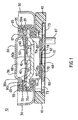
- an end cap assembly 10 intended for insertion into the open end of a cell case comprises a thermally activatable current interrupter subassembly 38 and a pressure relief subassembly 48 integrated therein.
- Subassemblies 38 and 48 are separated by a common support plate 60.
- Subassemblies 38 and 48 are held within a cover 30 which defines the outer wall of the end cap assembly 10.
- Interrupter subassembly 38 is defined at its top end by a cup-shaped end cap plate 20 and at its bottom end by a contact plate 15 which is welded to support plate 60.
- Cup shaped end cap plate 20 forms one of the external terminals of the cell.
- Support plate 60 separates chamber 68 within thermal subassembly 38 from chamber 78 within pressure relief subassembly 48.
- Contact plate 15 is electrically connected to support plate 60 which in turn is electrically connected to an electrode 88 (anode or cathode) of the cell when end cap assembly 10 is applied to a cell.
- a thermally responsive circuit interrupter mechanism (40,50) is provided to complete the circuit between contact plate 15 and end cap 20. If temperature within the cell exceeds a predetermined threshold value the interrupter mechanism activates breaking electrical contact between end cap 20 and contact plate 15 thereby preventing current from flowing through the cell.
- the pressure relief subassembly 48 comprises a thin metallic diaphragm 70 connected to a pressure resistant plate 80 which in turn is electrically connected to a cell electrode 88 through conductive tab 87 which is welded to plate 80.
- Pressure resistant plate is electrically conductive and of sufficient thickness that it does not substantially deform at elevated pressures at least up to about 600 psi (4.14 x 10 6 pascal). If gas pressure within the cell builds up to exceed a predetermined threshold value diaphragm 70 bulges outwardly to break electrical contact with pressure resistant plate 80 thereby preventing current from flowing to or from the cell.
- Pressure resistant plate 80 and support plate 60 preferably also have perforations 73 and 63, respectively, therein which helps to vent gas and relieve pressure buildup within the cell.
- end cap assembly 10 may be used in a rechargeable cell, for example, a lithium-ion rechargeable cell.
- a lithium-ion rechargeable cell is characterized by the transfer of lithium ions from the negative electrode to the positive electrode upon cell discharge and from the positive electrode to the negative electrode upon cell charging. It may typically have a positive electrode of lithium cobalt oxide (Li x CoO 2 ) or lithium manganese oxide of spinel crystalline structure (Li x Mn 2 O 4 ) and a carbon negative electrode.
- the negative electrode constitutes the anode of the cell during discharge and the cathode during charging and the positive electrode constitutes the cathode of the cell during discharge and the anode during charging.
- the electrolyte for such cells may comprise a lithium salt dissolved in a mixture of non-aqueous solvents.
- the salt may be LiPF 6 and the solvents may advantageously include dimethyl carbonate (DMC) ethylene carbonate (EC), propylene carbonate (PC) and mixtures thereof.
- DMC dimethyl carbonate
- EC ethylene carbonate
- PC propylene carbonate
- the present invention is applicable as well to other rechargeable cells, for example, nickel metal hydride cells and nickel cadmium cells.
- End cap assembly 10 comprises an end cap terminal 20 which is typically the positive terminal of the rechargeable cell, a metal support plate 60 which forms a support base under the cap plate 20, and an insulator disk 35 between end cap 20 and support plate 60.
- Cap assembly 10 is advantageously also provided with a pressure relief diaphragm 70 below support plate 60 as shown in Fig. 1.
- Diaphragm 70 may be welded to an underlying pressure resistant plate 80. This may be conveniently done by welding the base 72 of diaphragm 70 to a raised portion 82 of underlying pressure resistant plate 80. Diaphragm 70 should be of material that is electrically conductive and of minimal thickness of between about 0.1 and 0.5 millimeter, depending on the pressure at which the diaphragm is intended to actuate. The diaphragm 70 may desirably be of aluminum. The diaphragm 70 is advantageously coined so that it ruptures at a predetermined pressure. That is, the diaphragm surface may be stamped or etched so that a portion of the surface is of smaller thickness than the remainder.
- One preferred diaphragm 70 for use in the present invention is coined to impose a semicircular or "C" shaped groove 70a in its surface.
- the shape of the groove advantageously is the same or similar to the shape of a major portion of the peripheral edge of diaphragm 70 and positioned advantageously in proximity to the peripheral edge.
- the particular pressure at which venting takes place is controllable by varying parameters such as the depth, location or shape of the groove as well as hardness of the material. When pressure becomes excessive the diaphragm will rupture along the groove line.
- End cap 20 and support plate 60 define a chamber 68 therebetween in which is situated a thermally activated current interrupter subassembly 38.
- Insulator disk 35 is formed of a peripheral base portion 35a and a downwardly sloping arm 35b extending therefrom. Arm 35b extends into chamber 68.
- Diaphragm 70 is designed to rupture when gas buildup within the cell reaches a predetermined threshold level. The region between support plate 60 and diaphragm 70 forms a chamber 78 into which gas buildup within the cell may vent upon rupture of diaphragm 70.
- Current interrupter subassembly 38 comprises a thermally responsive bimetallic disk 40, a metallic contact plate 15 in electrical contact with a resilient springlike member 50.
- resilient member 50 may be formed of a single flexible member having an outer circular peripheral portion 50a from which a disk retainer tab portion 50c extends radially inward to generally hold bimetallic disk 40 freely in place during any orientation of the cell while not restricting its snap acting movement. This member can be welded at one point of outer portion 50a to end cap plate 20 with a center contact portion 50b in contact with plate 15. Additionally, contact portion 50b can be designed with a reduced cross sectional area so that it can act as a disintegratable fuse link to protect against power surge conditions.
- Bimetallic disk 40 is positioned to freely engage sloping arms 35b of insulator disk 35 which arms act as the disk seat for disk 40.
- Bimetallic disk 40 also preferably includes a central aperture for receiving a raised contacting portion of metallic contact plate 15.
- Contact plate 15 is preferably welded to support plate 60 and provides a surface for resilient member 50 to rest as shown in Figure 1.
- the grommet 25 serves to electrically insulate the end cap 20 from the crimp ring 55 and also to form a seal between support plate 60 and crimp ring 55.
- the cover 30 of the end cap assembly 10 may be formed from truncated cylindrical member shown best in Figure 5. In a completed cell assembly (Fig. 8) the outside surface of cover 30 will come into contact with the inside surface of cell casing 90.
- Support plate 60 provides a base for components of subassembly 38 to rest and preferably is of bow shape to maintain active radial compressive force against the inside surface of grommet 25.
- Support plate 60 may be provided with perforations 63 in its surface to vent gas to upper chamber 68 when diaphragm 70 ruptures. Gas which passes into upper chamber 68 will vent to the external environment through primary vent holes 67 in end cap 20.
- the end cap assembly cover 30 is in contact with the cell casing 90 which is in electrical contact with the opposite terminal, typically the negative terminal in the case of a lithium-ion rechargeable cell.
- grommet 25 provides electrical insulation between end cap 20 and outer wall 30, that is, between the two terminals of the cell thereby preventing shorting of the cell.
- Diaphragm 70 is preferably in the shape of a cup comprised of aluminum having a thickness advantageously of between about 3 and 10 mil (0.075 to 0.25 mm). At such thickness the weld between diaphragm base 72 and support plate 80 breaks and the diaphragm base 72 bulges and separates from support plate 80 (Fig. 3) when internal gas pressure within the cell rises to a threshold value of at least between about 100 psi and 200 psi (6.894 x 10 5 and 13.89 x 10 5 pascal).
- diaphragm base 72 can be conveniently adjusted to bulge at other pressure levels.
- the separation of diaphragm base 72 from plate 80 breaks all electrical contact between the diaphragm 70 and plate 80. This separation also breaks the electrical pathway between end cap 20 and the cell electrode 88 in contact with plate 80 so that current can no longer flow to or from the cell, in effect shutting down the cell.
- vent diaphragm 70 Even after the current path is broken if the pressure within the cell continues to rise for other reasons, for example, heating in an oven, the vent diaphragm 70 will also rupture preferably at a threshold pressure of at least between about 250 and 400 psi (17.2 x 10 5 and 27.6 x 10 5 pascal) to prevent cell explosion. In such extreme circumstances the rupture of vent diaphragm 70 allows gas from the cell interior to vent through vent holes 73 (Figs. 1 and 6) in pressure resistant plate 80 whereupon the gas enters lower chamber 78 (Fig. 1). The gas will then pass from lower chamber 78 to upper chamber 68 through vent holes 63 in the support plate 60 (Fig. 1) and if needed vent holes (not shown) in insulator disk 35. Gas collected in the upper chamber 68 will vent to the external environment through primary vent holes 67 in the end cap plate 20.
- plate 80 is in electrical contact with diaphragm 70 and diaphragm 70 is in electrical contact with support plate 60.
- Support plate 60 is in electrical contact with contact plate 15 which is in electrical contact with resilient member 50 which in turn is in electrical contact with end cap 20.
- electrical contact between the electrode 88 in contact with pressure plate 80 and end cap 20 may be interrupted in two ways. As above described if pressure builds up in the cell to a predetermined threshold, contact between diaphragm 70 and pressure plate 80 is broken as diaphragm base 72 bulges away from pressure plate 80. This interruption in the circuit prevents current from flowing to or from the cell.
- the bimetallic disk 40 is preferably not physically attached to underlying insulator disk 35 but rather is free to move, that is it rests in free floating condition on disk arm 35b as shown in Fig. 1. In such design current does not pass through the bimetallic disk 40 at any time regardless of whether the cell is charging or discharging. This is because disk 40 when inactivated is not in electrical contact with contact plate 15. However, should the cell overheat beyond a predetermined threshold temperature, bimetallic disk 40 is designed to the appropriate calibration such that it snaps or deforms (Fig. 2) causing it to push resilient member 50 away from contact plate 15 thereby preventing current from flowing between the cell terminals.
- the bimetallic disk 40 is calibrated so that it has a predetermined dished shape which allows the disk to actuate when a given threshold temperature is reached.
- the free floating design of bimetallic disk 40 on insulator disk arm 35b as above described does not permit current to pass therethrough at any time regardless of whether the cell is charging or discharging. This makes the calibration of disk 40 easier and more accurate, since there is no heating effect caused by current flow through bimetallic disk 40 (I 2 R heating).
- Bimetallic disk 40 may conveniently comprise two layers of dissimilar metals having different coefficient of thermal expansion.
- the top layer of bimetallic disk 40 (the layer closest to end cap 20) may be composed of a high thermal expansion metal, preferably nickel-chromium-iron alloy and the underlying or bottom layer may be composed of a low thermal expansion metal, preferably nickel-iron alloy.
- disk 40 may activate when temperature rises to at least between about 60 to 75°C. causing disk 40 to deform sufficiently to push resilient member 50 away from contact with contact plate 15. It is also possible to choose the high and low thermal expansion metal layers such that the disk 40 will not reset except at a temperature below -20°C. which in most applications makes the device a single action thermostatic device.
- End cap 20 is preferably of stainless steel or nickel plated steel of between about 8 to 15 mil (0.2 and 0.375 mm) thickness to provide adequate support, strength and corrosion resistance.
- the outer wall 30 of the end cap assembly 10 is also preferably of stainless steel or nickel plated steel having a thickness of between about 8 and 15 mil. (0.2 and 0.375 mm.)
- Pressure plate 80 is preferably of aluminum having a thickness between about 10 and 20 mils (0.25 and 0.5 mm) which may be reduced at the center to between about 2 and 5 mils (0.05 and 0.125 mm) at the point of welded contact with diaphragm base 72.
- Insulator standoff ring 42 may be composed of a high temperature thermoplastic material such as high temperature polyester for strength and durability available under the trade designation VALOX from General Electric Plastics Company.
- Crimp ring 55 is preferably of stainless steel or nickel plated steel having a thickness between about 8 and 15 mils (0.2 and 0.375 mm) for strength and corrosion resistance.
- Diaphragm 70 is preferably of aluminum having a thickness of between about 3 and 10 mils (0.075 and 0.25 mm). At such thickness the diaphragm will break away from its weld to pressure plate 80 when the internal gas pressure exceeds a threshold pressure between about 100 and 250 psi (6.89 x 10 5 and 17.2 x 10 5 pascal).
- the insulator disk 35 on which bimetallic disk 40 rests is preferably of a material of high compressive strength and high thermal stability and low mold shrinkage.
- a suitable material for disk 35 is a liquid crystal polymer or the like of thickness between about 10 and 30 mils (0.25 and 0.75 mm) available under the trade designation VECTRA from the Celanese Co.
- Support plate 60 is preferably of stainless steel or nickel plated steel to provide adequate strength and corrosion resistance at a thickness of between about 10 and 30 mils (0.25 and 0.75 mm).
- Resilient member 50 is advantageously formed of beryllium-copper, nickel-copper alloy, stainless steel or the like which has good spring action and excellent electrical conductivity.
- a suitable thickness for resilient member 50 when formed of beryllium-copper or nickel-copper alloy is between about 3 and 8 mils (0.075 and 0.2 mm) to give sufficient strength and current carrying capability.
- This material may be plated or inlayed with silver or gold at the contact region to provide lower electrical resistance in this area.
- Contact plate 15 is advantageously formed of cold rolled steel plated with a precious metal such as gold or silver to lower contact resistance and improve reliability. It may also be formed of a nickel-copper clad alloy, stainless steel, or nickel-plated steel.
- Grommet 25 typically is made of polymeric material such as nylon or polypropylene.
- the seal around the end cap assembly components should be hermetic in order that electrolyte, both in the form of liquid and vapor, is prevented from entering into the end cap chambers or from leaving the cell.
- end cap assembly 10 After the end cap assembly 10 is completed it may be inserted into the open end 95 of a cylindrical cell case 90 shown in Figure 7.
- the circumferential edge of cell casing 90 at the open end thereof is welded to the outer wall of cover 30 of end cap assembly 10 to provide a hermetically tight seal between end cap assembly 10 and the cell casing 90.
- the radial pressure of the circumferential wall of crimp ring 55 against grommet 25 and diaphragm 70 produces a hermetically tight seal around the interior components of end cap assembly 10.
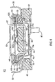
- FIG. 4 An alternative embodiment of the end cap design having both a pressure relief mechanism and thermally activated current interrupt mechanism integrated therein is shown as end cap assembly 110 in Figure 4.
- the embodiment of Figure 4 is similar to that described above with respect to Figures 1-3 except that a bimetallic disk is not employed to activate the springlike mechanism. Instead a thermal pellet 175 is provided to hold a resilient springlike member 150 in electrical contact with contact plate 115.
- Contact plate 115 in turn is in electrical contact with end cap plate 20.
- Resilient member 150 may comprise an elongated metallic arm 150a which is welded at one end to support plate 60. Support plate 60 is in electrical contact with diaphragm 70 which in turn is welded to a raised portion 82 of underlying pressure resistant plate 80.
- An electrode tab 87 is in electrical contact with plate 80.
- Resilient member 150 preferably terminates at its opposite end in a cup or convex shaped portion 150b which contacts contact plate 115. There is an electrical insulator disk 120 over the peripheral edge 60a of support plate 60 to prevent direct contact between support plate 60 and contact plate 115. Thus, there will be electrical contact between support plate 60 and end cap 20 as long as resilient member 150 is held pressed against contact plate 115. Support plate 60 in turn is in electrical contact with aluminum diaphragm 70 which is in contact with plate 80 and a cell electrode 88 through tab 87 when the end cap assembly 110 is applied to a cell. (End cap assembly 110 may be applied to a cell by inserting it into the open end of a cylindrical casing 90 in the same manner as above described with reference to the embodiment shown in Figure 1).
- resilient member 150 As resilient member 150 is held pressed against contact plate 115 by thermal pellet 175, there is electrical contact between a cell electrode 88 (through tab 87) and end cap plate 20 permitting normal cell operation. If the cell overheats beyond a predetermined threshold temperature pellet 175 melts thereby removing support for resilient member 150. Melting of pellet 175 causes resilient member 150 to snap downwardly and break electrical contact with contact plate 115. This in effect severs the electrical pathway between the electrode tab 87 and end cap 20 thus preventing current from flowing to or from the cell.
- diaphragm 70 will rupture thereby severing electrical, contact between plate 80 and diaphragm 70 and also allows gas to escape to the external environment through vent holes 63 and 67 in support plate 60 and end cap 20, respectively.
- Preferred materials for the end cap 20, support plate 60, contact plate 115 and aluminum diaphragm 70 referenced in the embodiment shown in Figure 4 may be the same as described for the corresponding elements having the same reference numerals shown in Figures 1-3.
- Contact plate 115 is preferably formed of stainless steel or nickel plated cold rolled steel plated with silver or gold to lower its contact resistance.
- the insulator disk 120 shown in Figure 4 is preferably made of a high temperature thermoplastic material having excellent dielectric properties.
- a preferred material for disk 120 may be a polyimide available under the trade designation KAPTON from E.I. DuPont Co. or high temperature polyester available under the trade designation VALOX from General Electric Plastics Co.
- Resilient member 150 may advantageously be formed of beryllium-copper alloy of thickness between about 5 and 10 mils (0.125 and 0.25 mm) to provide good conductivity when in contact with plate 115 and reliable spring action when the pressure of pellet 175 against it is removed. Additionally, the resilient arm 150 may be plated with silver or gold to increase its conductivity.
- the thermal pellet 175 is advantageously formed of a polymer having a relatively low melting point, e.g., between about 65°C. and 100°C. but yet excellent compressive strength to keep the resilient arm 150 in place during normal cell operation.
- a suitable material for thermal pellet 175 having such properties is a polyethylene wax available under the trade designation POLYWAX from Petrolyte Co. A thermal pellet 175 of such polyethylene wax melts within a desirable temperature range of between about 75°C. and 80°C.
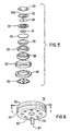
- FIG. 5 An exploded view of the end cap assembly 10 of Figure 1 is shown in Figure 5.
- the end cap assembly 10 may be made by assembling the components shown in Figure 5 in the following order: A preassembly is formed comprising components 20, 50, 40, 35, 15, 60, 70, 25, and 55. This is conveniently accomplished by first inserting plastic grommet 25 into crimp ring 55, then inserting vent diaphragm 70 into grommet 25 and then inserting support plate 60 with contact plate 15 welded thereto into vent diaphragm 70. Thereupon insulator disk 35 is placed around contact plate 15 and bimetallic disk 40 is placed to rest on downwardly sloping arm 35b of insulator disk 35.
- Bimetallic disk 40 is not bonded to insulator disk 35 but rests thereon in a free floating condition, with the insulator disk helping to act as positioning means for the bimetallic disk.
- the top surface of the outer end of resilient springlike member 50 is welded to the circumferential edge of end cap 20.
- the end cap 20 with resilient member 50 welded thereto is then placed over insulator disk 35 so that the raised central portion of contact plate 15 contacts the interior end of resilient member 50 and the bottom surface of the outer end of resilient member 50 contacts the circumferential edge of insulator disk 35.
- the outer end of resilient member 50 is wedged between end cap 20 and insulator disk 35 and the opposite or inner end of member 50 is in contact with contact plate 15.
- ring 55 is mechanically crimped over the top edge of grommet 25 to hold the top end of grommet 25 tightly pressed against the circumferential edge of end cap 20.
- This crimping is accomplished by applying mechanical force along the centroidal (vertical) axis of ring 55.
- mechanical pressure is applied radially to the walls of crimp ring 55, thereby completing assembly of the preassembly.
- the radial crimping serves to keep the preassembly internal components tightly and hermetically sealed within the ring 55.
- the preassembly is then inserted into metallic cover 30 so that the bottom surface of crimp ring 55 rests against the bottom inside edge of cover 30.
- end cap assembly 10 may be applied to a cell, for example, by inserting it into the open end of the cylindrical casing 90 of a cell as shown in Figure 7 and welding the outer surface of cover 30 to the inside surface of the cylindrical casing 90 at the open end 95 thereof. This results in cell 100 shown in Figure 8 with end cap assembly 10 being tightly sealed within the cylindrical casing 90 and the end cap plate 20 forming a terminal of the cell.
Landscapes
- Chemical & Material Sciences (AREA)
- Chemical Kinetics & Catalysis (AREA)
- Electrochemistry (AREA)
- General Chemical & Material Sciences (AREA)
- Connection Of Batteries Or Terminals (AREA)
- Gas Exhaust Devices For Batteries (AREA)
- Primary Cells (AREA)
- Hybrid Cells (AREA)
- Battery Mounting, Suspending (AREA)
Applications Claiming Priority (5)
| Application Number | Priority Date | Filing Date | Title |
|---|---|---|---|
| US1515396P | 1996-04-10 | 1996-04-10 | |
| US15153P | 1996-04-10 | ||
| US720585 | 1996-10-02 | ||
| US08/720,585 US5750277A (en) | 1996-04-10 | 1996-10-02 | Current interrupter for electrochemical cells |
| PCT/US1997/005928 WO1997038454A2 (en) | 1996-04-10 | 1997-04-10 | Current interrupter for electrochemical cells |
Publications (2)
| Publication Number | Publication Date |
|---|---|
| EP0925611A2 EP0925611A2 (en) | 1999-06-30 |
| EP0925611B1 true EP0925611B1 (en) | 2005-06-22 |
Family
ID=26687018
Family Applications (1)
| Application Number | Title | Priority Date | Filing Date |
|---|---|---|---|
| EP97920291A Expired - Lifetime EP0925611B1 (en) | 1996-04-10 | 1997-04-10 | Current interrupter for electrochemical cells |
Country Status (12)
Cited By (2)
| Publication number | Priority date | Publication date | Assignee | Title |
|---|---|---|---|---|
| CN104037018A (zh) * | 2014-06-12 | 2014-09-10 | 扬州宝珠电器有限公司 | 触点开距增幅性温度传感器 |
| EP4443608A1 (de) * | 2023-04-04 | 2024-10-09 | Volkswagen Ag | Batteriezellenanordnung mit mindestens zwei batteriezellen, insbesondere für ein fahrzeug |
Families Citing this family (45)
| Publication number | Priority date | Publication date | Assignee | Title |
|---|---|---|---|---|
| US5879832A (en) * | 1996-10-02 | 1999-03-09 | Duracell Inc. | Current interrupter for electrochemical cells |
| US5939217A (en) * | 1996-10-29 | 1999-08-17 | Sony Chemicals Corporation | Battery and protecting element therefor |
| JPH10294097A (ja) * | 1997-02-24 | 1998-11-04 | Mitsubishi Electric Corp | 薄型電池 |
| CA2233390A1 (en) | 1997-05-02 | 1998-11-02 | William F. Quinn | Thermal switch assembly |
| US6069551A (en) * | 1997-05-02 | 2000-05-30 | Therm-O-Disc, Incorporated | Thermal switch assembly |
| US6083639A (en) * | 1997-08-22 | 2000-07-04 | Duracell Inc. | Current interrupter for electrochemical cells |
| US5844464A (en) * | 1997-11-24 | 1998-12-01 | Therm-O-Disc, Incorporated | Thermal switch |
| US6210824B1 (en) | 1998-01-15 | 2001-04-03 | Texas Instruments Incorporated | Current interrupt apparatus for electrochemical cells |
| US6204635B1 (en) | 1998-05-22 | 2001-03-20 | Texas Instruments Incorporated | Current interrupt apparatus particularly adapted for use with prismatic electrochemical cells |
| US6524739B1 (en) * | 1998-08-25 | 2003-02-25 | Matsushita Electric Industrial Co., Ltd. | Secondary battery |
| US6018286A (en) * | 1998-11-20 | 2000-01-25 | Therm-O-Disc, Incorporated | Thermal switch |
| US6239686B1 (en) | 1999-08-06 | 2001-05-29 | Therm-O-Disc, Incorporated | Temperature responsive switch with shape memory actuator |
| US6342826B1 (en) | 1999-08-11 | 2002-01-29 | Therm-O-Disc, Incorporated | Pressure and temperature responsive switch assembly |
| US6743503B1 (en) | 1999-10-05 | 2004-06-01 | Seagate Technology Llc | Ultra-thin seed layer for multilayer superlattice magnetic recording media |
| US6570749B1 (en) * | 2000-07-14 | 2003-05-27 | Advanced Battery Technology Ltd | Over-current and thermal protection device |
| JP2002358939A (ja) * | 2001-05-31 | 2002-12-13 | Gs-Melcotec Co Ltd | 電 池 |
| US20030113622A1 (en) * | 2001-12-14 | 2003-06-19 | Blasi Jane A. | Electrolyte additive for non-aqueous electrochemical cells |
| US20030162099A1 (en) * | 2002-02-28 | 2003-08-28 | Bowden William L. | Non-aqueous electrochemical cell |
| CN100541867C (zh) * | 2004-04-13 | 2009-09-16 | 株式会社Lg化学 | 包括具有保护器元件的电极引线的电化学装置 |
| US7285356B2 (en) * | 2004-07-23 | 2007-10-23 | The Gillette Company | Non-aqueous electrochemical cells |
| US7479348B2 (en) * | 2005-04-08 | 2009-01-20 | The Gillette Company | Non-aqueous electrochemical cells |
| US8071233B2 (en) | 2006-06-27 | 2011-12-06 | Boston-Power, Inc. | Integrated current-interrupt device for lithium-ion cells |
| US20080248375A1 (en) * | 2007-03-26 | 2008-10-09 | Cintra George M | Lithium secondary batteries |
| US20080240480A1 (en) * | 2007-03-26 | 2008-10-02 | Pinnell Leslie J | Secondary Batteries for Hearing Aids |
| KR101521158B1 (ko) * | 2007-06-22 | 2015-05-18 | 보스톤-파워, 인크. | 리튬-이온 전지에 대한 cid 보유 장치 |
| DE102007033427A1 (de) * | 2007-07-18 | 2009-01-22 | Robert Bosch Gmbh | Anordnung mit einem Gehäuse |
| US20100033295A1 (en) | 2008-08-05 | 2010-02-11 | Therm-O-Disc, Incorporated | High temperature thermal cutoff device |
| US8642195B2 (en) | 2008-12-19 | 2014-02-04 | Boston-Power, Inc. | Modular CID assembly for a lithium ion battery |
| CN103515041B (zh) | 2012-06-15 | 2018-11-27 | 热敏碟公司 | 用于热截止装置的高热稳定性丸粒组合物及其制备方法和用途 |
| DE102013013662A1 (de) | 2013-08-16 | 2015-02-19 | Audi Ag | Sicherungsvorrichtung |
| JP5910624B2 (ja) * | 2013-12-26 | 2016-04-27 | 株式会社豊田自動織機 | 電池パック |
| US10734625B2 (en) | 2014-10-17 | 2020-08-04 | Gp Batteries International Limited | Battery including safety vent assembly |
| JP6565412B2 (ja) * | 2015-07-21 | 2019-08-28 | 三洋電機株式会社 | 二次電池 |
| JP6661485B2 (ja) * | 2015-09-16 | 2020-03-11 | パナソニック株式会社 | 非水電解質二次電池 |
| JP6821309B2 (ja) * | 2016-03-07 | 2021-01-27 | 三洋電機株式会社 | 二次電池および二次電池集合体 |
| KR102093386B1 (ko) * | 2016-06-22 | 2020-03-25 | 주식회사 엘지화학 | 이차 전지 및 이차 전지의 전류 차단 방법 |
| US10818906B2 (en) * | 2017-05-01 | 2020-10-27 | American Lithium Energy Corporation | Negative thermal expansion current interrupter |
| US11476551B2 (en) | 2017-07-31 | 2022-10-18 | 24M Technologies, Inc. | Current interrupt devices using shape memory materials |
| US10854869B2 (en) | 2017-08-17 | 2020-12-01 | 24M Technologies, Inc. | Short-circuit protection of battery cells using fuses |
| US10461291B2 (en) * | 2017-12-12 | 2019-10-29 | Ford Global Technologies, Llc | Current-interrupt device for battery cell |
| CN108565390B (zh) * | 2018-04-24 | 2024-07-26 | 苏州聚天合科技有限公司 | 一种应用于新能源电池的电流自动切断装置 |
| CN108390007B (zh) * | 2018-04-24 | 2024-07-19 | 苏州聚天合科技有限公司 | 一种用于新能源电池电流自动切断的断电装置 |
| WO2020160322A1 (en) | 2019-01-30 | 2020-08-06 | Horizon Pharma Rheumatology Llc | Tolerization reduces intolerance to pegloticase and prolongs the urate lowering effect (triple) |
| KR102609417B1 (ko) | 2019-06-11 | 2023-12-04 | 주식회사 엘지에너지솔루션 | Cid 필터 및 그 cid 필터를 포함하는 이차전지 |
| US12068486B2 (en) | 2020-06-04 | 2024-08-20 | 24M Technologies, Inc. | Electrochemical cells with one or more segmented current collectors and methods of making the same |
Family Cites Families (14)
| Publication number | Priority date | Publication date | Assignee | Title |
|---|---|---|---|---|
| US3373057A (en) * | 1965-10-24 | 1968-03-12 | Texas Instruments Inc | Battery having an automatic circuit breaker therein |
| US3617386A (en) * | 1970-04-30 | 1971-11-02 | Esb Inc | Sealed cell construction |
| US3996547A (en) * | 1974-09-05 | 1976-12-07 | Texas Instruments Incorporated | Motor protector apparatus |
| US4035552A (en) * | 1976-07-23 | 1977-07-12 | Gte Laboratories Incorporated | Electrochemical cell |
| US4188460A (en) * | 1978-05-01 | 1980-02-12 | P. R. Mallory & Co., Inc. | Internal battery fuse |
| CA2000873C (en) * | 1988-10-21 | 1999-12-14 | Shigeru Oishi | Cell having current cutoff valve |
| US4966822A (en) * | 1989-02-01 | 1990-10-30 | Johnston Lowell E | Battery assembly |
| US5080985A (en) * | 1989-12-07 | 1992-01-14 | Duracell Inc. | High pressure seal for alkaline cells |
| RU1715156C (ru) * | 1990-05-07 | 1994-10-30 | Научно-производственное предприятие "Сатурн" | Клапан для химического источника тока |
| US5041345A (en) * | 1990-06-08 | 1991-08-20 | Eveready Battery Company | Secondary seal for vented electrochemical cells |
| US5188909A (en) * | 1991-09-12 | 1993-02-23 | Eveready Battery Co., Inc. | Electrochemical cell with circuit disconnect device |
| US5567539A (en) * | 1994-05-23 | 1996-10-22 | Fuji Photo Film Co., Ltd. | Non-aqueous secondary cell |
| JP3565580B2 (ja) * | 1994-06-24 | 2004-09-15 | Fdk株式会社 | 防爆安全装置を備えた電池とその製造方法 |
| US5521021A (en) * | 1994-07-06 | 1996-05-28 | Alexander Manufacturing Corporation | Electric vehicle cell |
-
1996
- 1996-10-02 US US08/720,585 patent/US5750277A/en not_active Expired - Lifetime
-
1997
- 1997-04-10 AU AU24519/97A patent/AU2451997A/en not_active Abandoned
- 1997-04-10 TW TW086104616A patent/TW345756B/zh not_active IP Right Cessation
- 1997-04-10 DE DE69733609T patent/DE69733609T2/de not_active Expired - Lifetime
- 1997-04-10 CA CA002251100A patent/CA2251100C/en not_active Expired - Lifetime
- 1997-04-10 AT AT97920291T patent/ATE298465T1/de not_active IP Right Cessation
- 1997-04-10 CN CNB971944512A patent/CN1240145C/zh not_active Expired - Lifetime
- 1997-04-10 WO PCT/US1997/005928 patent/WO1997038454A2/en active IP Right Grant
- 1997-04-10 EP EP97920291A patent/EP0925611B1/en not_active Expired - Lifetime
- 1997-04-10 BR BR9708550-2A patent/BR9708550A/pt not_active IP Right Cessation
- 1997-04-10 RU RU98120486/09A patent/RU2216824C2/ru active
- 1997-04-10 JP JP53648497A patent/JP4245663B2/ja not_active Expired - Lifetime
Cited By (2)
| Publication number | Priority date | Publication date | Assignee | Title |
|---|---|---|---|---|
| CN104037018A (zh) * | 2014-06-12 | 2014-09-10 | 扬州宝珠电器有限公司 | 触点开距增幅性温度传感器 |
| EP4443608A1 (de) * | 2023-04-04 | 2024-10-09 | Volkswagen Ag | Batteriezellenanordnung mit mindestens zwei batteriezellen, insbesondere für ein fahrzeug |
Also Published As
| Publication number | Publication date |
|---|---|
| CN1218578A (zh) | 1999-06-02 |
| US5750277A (en) | 1998-05-12 |
| EP0925611A2 (en) | 1999-06-30 |
| WO1997038454A2 (en) | 1997-10-16 |
| CN1240145C (zh) | 2006-02-01 |
| DE69733609T2 (de) | 2006-05-11 |
| RU2216824C2 (ru) | 2003-11-20 |
| BR9708550A (pt) | 2000-01-04 |
| WO1997038454A3 (en) | 1997-12-31 |
| ATE298465T1 (de) | 2005-07-15 |
| TW345756B (en) | 1998-11-21 |
| DE69733609D1 (de) | 2005-07-28 |
| JP2000508468A (ja) | 2000-07-04 |
| JP4245663B2 (ja) | 2009-03-25 |
| HK1018547A1 (en) | 2000-04-14 |
| AU2451997A (en) | 1997-10-29 |
| CA2251100C (en) | 2003-09-23 |
| CA2251100A1 (en) | 1997-10-16 |
Similar Documents
| Publication | Publication Date | Title |
|---|---|---|
| EP0925611B1 (en) | Current interrupter for electrochemical cells | |
| EP0907974B1 (en) | Current interrupter for electrochemical cells | |
| US5879832A (en) | Current interrupter for electrochemical cells | |
| US6037071A (en) | Current interrupter for electrochemical cells | |
| US5998051A (en) | Current interrupter for electrochemical cells | |
| EP1029378B1 (en) | Current interrupter for electrochemical cells | |
| HK1018547B (en) | Current interrupter for electrochemical cells | |
| RU2195749C2 (ru) | Узел торцевой заглушки для гальванического элемента и гальванический элемент | |
| HK1017154B (en) | Current interrupter for electrochemical cells | |
| MXPA98008383A (es) | Interruptor de corriente para celdas electroquimicas | |
| MXPA99009232A (en) | Current interrupter for electrochemical cells | |
| MXPA99009231A (en) | Current interrupter for electrochemical cells | |
| MXPA00001809A (en) | Current interrupter for electrochemical cells |
Legal Events
| Date | Code | Title | Description |
|---|---|---|---|
| PUAI | Public reference made under article 153(3) epc to a published international application that has entered the european phase |
Free format text: ORIGINAL CODE: 0009012 |
|
| 17P | Request for examination filed |
Effective date: 19981109 |
|
| AK | Designated contracting states |
Kind code of ref document: A2 Designated state(s): AT BE CH DE DK ES FI FR GB GR IE IT LI LU NL PT SE |
|
| 17Q | First examination report despatched |
Effective date: 19990819 |
|
| GRAP | Despatch of communication of intention to grant a patent |
Free format text: ORIGINAL CODE: EPIDOSNIGR1 |
|
| GRAS | Grant fee paid |
Free format text: ORIGINAL CODE: EPIDOSNIGR3 |
|
| GRAA | (expected) grant |
Free format text: ORIGINAL CODE: 0009210 |
|
| AK | Designated contracting states |
Kind code of ref document: B1 Designated state(s): AT BE CH DE DK ES FI FR GB GR IE IT LI LU NL PT SE |
|
| PG25 | Lapsed in a contracting state [announced via postgrant information from national office to epo] |
Ref country code: NL Free format text: LAPSE BECAUSE OF FAILURE TO SUBMIT A TRANSLATION OF THE DESCRIPTION OR TO PAY THE FEE WITHIN THE PRESCRIBED TIME-LIMIT Effective date: 20050622 Ref country code: LI Free format text: LAPSE BECAUSE OF FAILURE TO SUBMIT A TRANSLATION OF THE DESCRIPTION OR TO PAY THE FEE WITHIN THE PRESCRIBED TIME-LIMIT Effective date: 20050622 Ref country code: IT Free format text: LAPSE BECAUSE OF FAILURE TO SUBMIT A TRANSLATION OF THE DESCRIPTION OR TO PAY THE FEE WITHIN THE PRE;WARNING: LAPSES OF ITALIAN PATENTS WITH EFFECTIVE DATE BEFORE 2007 MAY HAVE OCCURRED AT ANY TIME BEFORE 2007. THE CORRECT EFFECTIVE DATE MAY BE DIFFERENT FROM THE ONE RECORDED.SCRIBED TIME-LIMIT Effective date: 20050622 Ref country code: FI Free format text: LAPSE BECAUSE OF FAILURE TO SUBMIT A TRANSLATION OF THE DESCRIPTION OR TO PAY THE FEE WITHIN THE PRESCRIBED TIME-LIMIT Effective date: 20050622 Ref country code: CH Free format text: LAPSE BECAUSE OF FAILURE TO SUBMIT A TRANSLATION OF THE DESCRIPTION OR TO PAY THE FEE WITHIN THE PRESCRIBED TIME-LIMIT Effective date: 20050622 Ref country code: AT Free format text: LAPSE BECAUSE OF FAILURE TO SUBMIT A TRANSLATION OF THE DESCRIPTION OR TO PAY THE FEE WITHIN THE PRESCRIBED TIME-LIMIT Effective date: 20050622 |
|
| REG | Reference to a national code |
Ref country code: GB Ref legal event code: FG4D |
|
| REG | Reference to a national code |
Ref country code: CH Ref legal event code: EP |
|
| REG | Reference to a national code |
Ref country code: IE Ref legal event code: FG4D |
|
| REF | Corresponds to: |
Ref document number: 69733609 Country of ref document: DE Date of ref document: 20050728 Kind code of ref document: P |
|
| REG | Reference to a national code |
Ref country code: HK Ref legal event code: GR Ref document number: 1018547 Country of ref document: HK |
|
| PG25 | Lapsed in a contracting state [announced via postgrant information from national office to epo] |
Ref country code: SE Free format text: LAPSE BECAUSE OF FAILURE TO SUBMIT A TRANSLATION OF THE DESCRIPTION OR TO PAY THE FEE WITHIN THE PRESCRIBED TIME-LIMIT Effective date: 20050922 Ref country code: GR Free format text: LAPSE BECAUSE OF FAILURE TO SUBMIT A TRANSLATION OF THE DESCRIPTION OR TO PAY THE FEE WITHIN THE PRESCRIBED TIME-LIMIT Effective date: 20050922 Ref country code: DK Free format text: LAPSE BECAUSE OF FAILURE TO SUBMIT A TRANSLATION OF THE DESCRIPTION OR TO PAY THE FEE WITHIN THE PRESCRIBED TIME-LIMIT Effective date: 20050922 |
|
| PG25 | Lapsed in a contracting state [announced via postgrant information from national office to epo] |
Ref country code: ES Free format text: LAPSE BECAUSE OF FAILURE TO SUBMIT A TRANSLATION OF THE DESCRIPTION OR TO PAY THE FEE WITHIN THE PRESCRIBED TIME-LIMIT Effective date: 20051003 |
|
| PG25 | Lapsed in a contracting state [announced via postgrant information from national office to epo] |
Ref country code: PT Free format text: LAPSE BECAUSE OF FAILURE TO SUBMIT A TRANSLATION OF THE DESCRIPTION OR TO PAY THE FEE WITHIN THE PRESCRIBED TIME-LIMIT Effective date: 20051129 |
|
| NLV1 | Nl: lapsed or annulled due to failure to fulfill the requirements of art. 29p and 29m of the patents act | ||
| REG | Reference to a national code |
Ref country code: CH Ref legal event code: PL |
|
| PG25 | Lapsed in a contracting state [announced via postgrant information from national office to epo] |
Ref country code: IE Free format text: LAPSE BECAUSE OF NON-PAYMENT OF DUE FEES Effective date: 20060410 |
|
| PLBE | No opposition filed within time limit |
Free format text: ORIGINAL CODE: 0009261 |
|
| STAA | Information on the status of an ep patent application or granted ep patent |
Free format text: STATUS: NO OPPOSITION FILED WITHIN TIME LIMIT |
|
| 26N | No opposition filed |
Effective date: 20060323 |
|
| EN | Fr: translation not filed | ||
| PG25 | Lapsed in a contracting state [announced via postgrant information from national office to epo] |
Ref country code: FR Free format text: LAPSE BECAUSE OF FAILURE TO SUBMIT A TRANSLATION OF THE DESCRIPTION OR TO PAY THE FEE WITHIN THE PRESCRIBED TIME-LIMIT Effective date: 20060818 |
|
| REG | Reference to a national code |
Ref country code: IE Ref legal event code: MM4A |
|
| REG | Reference to a national code |
Ref country code: GB Ref legal event code: 732E |
|
| PG25 | Lapsed in a contracting state [announced via postgrant information from national office to epo] |
Ref country code: LU Free format text: LAPSE BECAUSE OF NON-PAYMENT OF DUE FEES Effective date: 20060410 |
|
| PG25 | Lapsed in a contracting state [announced via postgrant information from national office to epo] |
Ref country code: FR Free format text: LAPSE BECAUSE OF FAILURE TO SUBMIT A TRANSLATION OF THE DESCRIPTION OR TO PAY THE FEE WITHIN THE PRESCRIBED TIME-LIMIT Effective date: 20050622 |
|
| PGFP | Annual fee paid to national office [announced via postgrant information from national office to epo] |
Ref country code: GB Payment date: 20160406 Year of fee payment: 20 Ref country code: DE Payment date: 20160405 Year of fee payment: 20 |
|
| PGFP | Annual fee paid to national office [announced via postgrant information from national office to epo] |
Ref country code: BE Payment date: 20160413 Year of fee payment: 20 |
|
| REG | Reference to a national code |
Ref country code: DE Ref legal event code: R071 Ref document number: 69733609 Country of ref document: DE |
|
| REG | Reference to a national code |
Ref country code: GB Ref legal event code: PE20 Expiry date: 20170409 |
|
| PG25 | Lapsed in a contracting state [announced via postgrant information from national office to epo] |
Ref country code: GB Free format text: LAPSE BECAUSE OF EXPIRATION OF PROTECTION Effective date: 20170409 |