EP0925517B1 - Echtzeit-, breitband-, zylindrisches, holographisches überwachungssystem - Google Patents
Echtzeit-, breitband-, zylindrisches, holographisches überwachungssystem Download PDFInfo
- Publication number
- EP0925517B1 EP0925517B1 EP97939832A EP97939832A EP0925517B1 EP 0925517 B1 EP0925517 B1 EP 0925517B1 EP 97939832 A EP97939832 A EP 97939832A EP 97939832 A EP97939832 A EP 97939832A EP 0925517 B1 EP0925517 B1 EP 0925517B1
- Authority
- EP
- European Patent Office
- Prior art keywords
- dimensional
- target
- data
- cylindrical
- instructions
- Prior art date
- Legal status (The legal status is an assumption and is not a legal conclusion. Google has not performed a legal analysis and makes no representation as to the accuracy of the status listed.)
- Expired - Lifetime
Links
Images


Classifications
-
- G—PHYSICS
- G01—MEASURING; TESTING
- G01S—RADIO DIRECTION-FINDING; RADIO NAVIGATION; DETERMINING DISTANCE OR VELOCITY BY USE OF RADIO WAVES; LOCATING OR PRESENCE-DETECTING BY USE OF THE REFLECTION OR RERADIATION OF RADIO WAVES; ANALOGOUS ARRANGEMENTS USING OTHER WAVES
- G01S13/00—Systems using the reflection or reradiation of radio waves, e.g. radar systems; Analogous systems using reflection or reradiation of waves whose nature or wavelength is irrelevant or unspecified
- G01S13/88—Radar or analogous systems specially adapted for specific applications
- G01S13/887—Radar or analogous systems specially adapted for specific applications for detection of concealed objects, e.g. contraband or weapons
-
- A—HUMAN NECESSITIES
- A61—MEDICAL OR VETERINARY SCIENCE; HYGIENE
- A61B—DIAGNOSIS; SURGERY; IDENTIFICATION
- A61B5/00—Measuring for diagnostic purposes; Identification of persons
- A61B5/05—Detecting, measuring or recording for diagnosis by means of electric currents or magnetic fields; Measuring using microwaves or radio waves
-
- A—HUMAN NECESSITIES
- A61—MEDICAL OR VETERINARY SCIENCE; HYGIENE
- A61B—DIAGNOSIS; SURGERY; IDENTIFICATION
- A61B5/00—Measuring for diagnostic purposes; Identification of persons
- A61B5/72—Signal processing specially adapted for physiological signals or for diagnostic purposes
- A61B5/7235—Details of waveform analysis
- A61B5/7253—Details of waveform analysis characterised by using transforms
- A61B5/7257—Details of waveform analysis characterised by using transforms using Fourier transforms
-
- G—PHYSICS
- G01—MEASURING; TESTING
- G01S—RADIO DIRECTION-FINDING; RADIO NAVIGATION; DETERMINING DISTANCE OR VELOCITY BY USE OF RADIO WAVES; LOCATING OR PRESENCE-DETECTING BY USE OF THE REFLECTION OR RERADIATION OF RADIO WAVES; ANALOGOUS ARRANGEMENTS USING OTHER WAVES
- G01S13/00—Systems using the reflection or reradiation of radio waves, e.g. radar systems; Analogous systems using reflection or reradiation of waves whose nature or wavelength is irrelevant or unspecified
- G01S13/88—Radar or analogous systems specially adapted for specific applications
- G01S13/89—Radar or analogous systems specially adapted for specific applications for mapping or imaging
-
- G—PHYSICS
- G01—MEASURING; TESTING
- G01S—RADIO DIRECTION-FINDING; RADIO NAVIGATION; DETERMINING DISTANCE OR VELOCITY BY USE OF RADIO WAVES; LOCATING OR PRESENCE-DETECTING BY USE OF THE REFLECTION OR RERADIATION OF RADIO WAVES; ANALOGOUS ARRANGEMENTS USING OTHER WAVES
- G01S7/00—Details of systems according to groups G01S13/00, G01S15/00, G01S17/00
- G01S7/02—Details of systems according to groups G01S13/00, G01S15/00, G01S17/00 of systems according to group G01S13/00
- G01S7/41—Details of systems according to groups G01S13/00, G01S15/00, G01S17/00 of systems according to group G01S13/00 using analysis of echo signal for target characterisation; Target signature; Target cross-section
- G01S7/411—Identification of targets based on measurements of radar reflectivity
- G01S7/412—Identification of targets based on measurements of radar reflectivity based on a comparison between measured values and known or stored values
-
- G—PHYSICS
- G01—MEASURING; TESTING
- G01V—GEOPHYSICS; GRAVITATIONAL MEASUREMENTS; DETECTING MASSES OR OBJECTS; TAGS
- G01V8/00—Prospecting or detecting by optical means
- G01V8/005—Prospecting or detecting by optical means operating with millimetre waves, e.g. measuring the black losey radiation
-
- G—PHYSICS
- G06—COMPUTING OR CALCULATING; COUNTING
- G06T—IMAGE DATA PROCESSING OR GENERATION, IN GENERAL
- G06T12/00—Tomographic reconstruction from projections
- G06T12/20—Inverse problem, i.e. transformations from projection space into object space
-
- G—PHYSICS
- G01—MEASURING; TESTING
- G01S—RADIO DIRECTION-FINDING; RADIO NAVIGATION; DETERMINING DISTANCE OR VELOCITY BY USE OF RADIO WAVES; LOCATING OR PRESENCE-DETECTING BY USE OF THE REFLECTION OR RERADIATION OF RADIO WAVES; ANALOGOUS ARRANGEMENTS USING OTHER WAVES
- G01S7/00—Details of systems according to groups G01S13/00, G01S15/00, G01S17/00
- G01S7/02—Details of systems according to groups G01S13/00, G01S15/00, G01S17/00 of systems according to group G01S13/00
- G01S7/04—Display arrangements
- G01S7/06—Cathode-ray tube displays or other two dimensional or three-dimensional displays
- G01S7/20—Stereoscopic displays; Three-dimensional [3D] displays; Pseudo-3D displays
-
- G—PHYSICS
- G06—COMPUTING OR CALCULATING; COUNTING
- G06T—IMAGE DATA PROCESSING OR GENERATION, IN GENERAL
- G06T2211/00—Image generation
- G06T2211/40—Computed tomography
- G06T2211/421—Filtered back projection [FBP]
Definitions
- the present invention relates to a method and apparatus useful for inspection of concealed objects. More specifically, the present invention relates to forming a cylindrical image with millimeter wave signals that are transmitted and received by a holographic array and that are reconstructed using Fast Fourier Transform Analysis.
- the method and apparatus have particular utility for personnel inspection in mass transportation centers.
- the holographic linear array of sequentially-switched millimeter-wave transmitter-receivers scanned quickly over a large aperture to actively illuminate the target as described in U.S. Patent 5,455,590 uses a single frequency that is coherent, which means the phase of the returned signal is recorded as well as the amplitude.
- the holographic linear array described in U.S. Patent 5 557 283 improves image quality by using a wideband system.
- the previous systems lack the capability of scanning an individual from all sides quickly without inconveniencing the individual. Specifically, to fully inspect a person for concealed objects, it is necessary to image the person from many viewing angles. With a planar aperture, a person is required to pose at a number of predetermined positions while images are acquired. To obtain a sufficient number of images (8-128), total imaging time may be as high as several minutes, which is unacceptable for high throughput applications including airports.
- the present invention disclosed herein involves a method and apparatus for achieving near real-time holographic imaging of concealed objects.
- a vertical linear antenna array is actuated over a circular path to obtain a 360° cylindrical scan of a covered target, for example a clothed individual.
- the data are in the form of unfocused or diverging millimeter wave illumination which is capable of penetrating a cover, for example clothing.
- the millimeter wave illumination must be mathematically focused or reconstructed into recognizable images.
- a completely new reconstruction algorithm is required to accept the wideband data gathered over a section of the 360° cylindrical aperture and form a fully focused three-dimensional image. Subsets of the 360° data may be used to form images of the target from any cylindrical viewing position or viewing angle.
- the present invention is an extension of the holographic imaging system from planar imaging operation viewing a single side to cylindrical imaging operation viewing multiple sides. Rather than forming an image of one side, for example a front view, the invention forms images from multiple sides.
- Wideband data are gathered over a two-dimensional cylindrical aperture.
- the use of a cylindrical aperture overcomes the single viewing angle limitation present in a planar aperture system.
- the term wideband refers to integrated sending and receiving of at least two frequencies, as opposed to separate sending and receiving of at least two frequencies.
- U.S. 5 557 283 describes the antenna array and bi-static, heterodyne, in- phase transceiver preferred for cylindrical imaging, as well as alternative transceivers useful for cylindrical imaging.
- the method and apparatus have an expanded depth of field and providing views or images from multiple viewing angles or multiple sides to accomplish near real-time imaging that is needed for personnel surveillance.
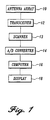
- the wideband cylindrical holographic system ( FIG. 1 ) is made up of an antenna array 10, transceiver 12 , scanner 13 , A/D converter 14 , computer 16 , and display 18 .
- a system diagram ( FIG. 2 ) shows a person 40 on a platform 41 within a scanner frame 42. The antenna array 10 is rotated about the person 40 to obtain the image(s).
- the person 40 to be scanned is directed to stand relatively still on the platform 41 of the scanner frame 42 while vertical linear antenna array 10 around the person 40 in a cylindrical manner. Millimeter-wave illumination from the antenna array 10 passes through clothing and is reflected from concealed objects. The reflected millimeter-wave signals are recorded by the imaging system and focused, or reconstructed, using a computer 16 into recognizable images of the subject revealing concealed objects.
- the cylindrical scanner's 43 function is simply to rotate the vertical antenna array(s) 10 about the target being scanned. For a person as a target, this requires a scanner approximately 2 meters in height.
- the radius of the scan should be in the range of 0.75 meters - 1.25 meters. The radius must be large enough that a person can easily enter and exit the system and should be as small as possible to minimize the footprint, or floorspace, required of the scanner.
- the antenna array 10 spans the vertical length of the aperture, typically about 2 meters for personnel surveillance.
- the millimeter-wave source is switched to each antenna element in the array.
- the array can be configured to transmit and receive from the same antenna element, however, a preferred configuration uses separate transmit and receive arrays.
- Logic circuitry sequences the transmit and receive antennas to transmit from one antenna and receive the reflected wideband signal from each of the two neighboring antennas in the receive row. This places a virtual sampling point half-way between each transmit and receive antenna.
- the transmit row and receive row are preferably offset by half the antenna spacing, so the effective sample spacing is one- half of the single-row antenna spacing. This sequencing scheme cannot be used on the last antenna element, so the effective number of sample points is reduced by one.
- sampling density needed for the arrays is determined by the millimeter-wave center-frequency and by the Nyquist sampling criterion. Generally, sampling on the order of one-half wavelength is optimal, with two- thirds wavelength providing acceptable results. For a 2 meter vertical array operating at 27 - 33 GHz, this would indicate that 300 - 400 antenna elements will be needed.
- the antenna array 10 may be a single transmit/receive antenna element that is moved across a two-dimensional aperture. It is preferred, that the antenna 10 be an array of antenna elements that is at least a single row of a plurality of antenna elements. Alternatively, antenna elements may be arranged so that one row is a set of transmit antenna elements and a second row is a set of receive antenna elements. Separate transmit and receive antenna elements are preferred for a wideband system to avoid the need of a multi-frequency circulator.
- Millimeter-wave switching is required in the cylindrical wideband holographic imaging system in order to provide high-speed sampling of the cylindrical aperture.
- a single transmit antenna and a single receive antenna must be individually connected to the transceiver.
- SPDT single pole double throw
- this array would be very bulky, and it would be difficult to arrange the outputs to have the desired spacing.
- a custom switch module such as the single-pole 8- throw (SP8T) switch described in 5 557 283, is desirable.
- SP8T switch module uses a binary tree structure composed of three layers of SPDT switch elements for a total of 7 SPDT elements.
- Each SPDT element contains a duroid fin-line printed circuit junction which uses shunt pin-diodes to direct the millimeter-wave signal to the desired output waveguide.
- the pin-diodes are controlled by electronic driver circuitry mounted in a housing on top of a split-block (not shown).
- One of these SP8T modules may be connected to 8 other SP8T modules to form a 64 element switch sub-array. Several of these switch sub-arrays can then be connected to the vertical linear antenna array 10 with the required number of antenna elements.
- the type of antenna element may be any type including but not limited to slot line, patch, endfire, waveguide, dipole, or any combination thereof.
- a preferred antenna element is a polyrod antenna element as described in 5 557 283.
- a bi-static heterodyne, in-phase only transceiver ( FIG. 3 ) is preferred.
- the RF VCO wideband signal is transmitted directly by the transmit antenna 50 .
- the received signal is received by the receiver 51 mixed in a mixer 52 and amplified (amplifier 53 to down-convert the received signal to the intermediate frequency (IF).
- the LO VCO oscillator 54 is offset in frequency from the RF VCO oscillator 55 by the IF frequency.
- an IF REF signal is obtained by mixing the RF VCO and LO VCO signals with a second mixer 56. This mixed signal is amplified and filtered in the amplifier 57 to remove higher frequency mixing products.
- in-phase signal (I).
- Alternative transceivers may be used including but not limited to those in 5 557 283. More preferred is bi-static heterodyne in-phase and quadrature transceiver ( FIG. 3a ) because the in-phase only transceiver requires data from the entire scanned volume whereas using the in-phase and quadrature transceiver permits shifting the origin or reference position to the center of the scan thereby permitting digitizing of data in a reduced volume surrounding the target.
- the wideband data is sampled vertically along the array and angularly over the 360° aperture and is digitized by an Analog to Digital converter (A/D) for subsequent storage in the computer.
- A/D Analog to Digital converter
- the reconstruction algorithm discussed below is applied to a segment of the 360° data to reconstruct a three-dimensional image of the target from a single viewing angle.
- the three-dimensional image is then collapsed into a fully-focused two-dimensional image of the target for display on the computer.
- a number of these viewing angles can then be integrated into a single computer animation showing a smooth rotation of the image of the target under surveillance.
- VCO DRIVERS board ARRAY-CPU INTERFACE board
- Analog to Digital converter (A/D) A/D
- other detailed components are set forth in 5 557 283.
- the measurement configuration is shown in FIG. 4, where the primed coordinates represent the transceiver position 1 , and the unprimed coordinates represent a single target point 2 in the target or image-space 3 . If the target 3 is characterized by a reflectivity function, f(x,y,z), then the response measured at the transceiver position 1 will be the superposition of the reflectivity function times the round trip phase to the target 4.
- the round-trip phase is 2 k ( Rcos ⁇ - x ) 2 + ( Rsin ⁇ - y ) 2 + ( z - z ') 2
- k ⁇ /c is the wavenumber, and the amplitude decay with range is not considered since it will have little impact on focusing the image. If needed, amplitude decay with range may be compensated for in the raw data by applying a numerical gain to the data from the transceiver. The numerical gain increases with range.
- the data could be collected in the time domain, as is common with acoustic data.
- the data in Equation 2 will be obtained by Fourier Transforming the gathered data, which is the echoed data in the time domain.
- This decomposition indicates that the spherical wave can be decomposed into equal amplitude and phase plane wave components emanating from the target point at ( x,y,z ).
- each plane wave component in the x-y plane is ⁇ which has limits of +/- ⁇ /2.
- the limits of the z-component of the wavenumber will be k z , ⁇ [-2 k ,2 k ].
- the data will be non-uniformly sampled in the spatial frequency domain and will therefore need to be interpolated onto a uniform ( k x ,k y , k z ) grid prior to computation of the final three-dimensional inverse Fourier Transform that yields the reconstructed image in rectangular coordinates
- a uniform ( k x ,k y , k z ) grid prior to computation of the final three-dimensional inverse Fourier Transform that yields the reconstructed image in rectangular coordinates
- the steps required to implement the reconstruction technique on a computer are outlined below.
- the data is discretized in ( ⁇ , ⁇ , z ) and the image is discretized in ( x,y,z ).
- Fourier Transforms will typically be done using the discrete Fast Fourier Transform algorithm.
- the steps of the reconstruction algorithm reside on the digital computer as
- Reconstructing a large number of frames, 8-128, preferably 32-128 frames permits smooth transitions between images, making the results suitable for computer animation at a rate from about 4 to 32 frames per second. It is further preferred that the frames are obtained from overlapping arc segments of data to improve smooth transitions. By observing a full animation, the subject is viewed from all angles without requiring inspector examination of separate still images.
- the actual data processing of the above described seven steps produces a single image from a single viewing angle or arc segment of the 360° data.
- Overlapping arc segments permits viewing around corners, within depressions or other topographical perturbations of the target.
- an imaging sequence may use 90° arc segments overlapped in 10° increments, or 0-90°, 10-100°, .. ., 350-80°, to form 36 images with illuminations centered at 10° increments.
- Each frame or arc segment reconstruction is computationally intensive. Therefore, high-speed image reconstruction is preferably achieved with high-speed parallel computer processors.
- each arc segment reconstruction is accomplished by a single processor module.
- Each processor module receives its arc segment data from a digital multiplexer.
- Use of the multiplexer permits presenting data that is identical in an overlap to several of the processor modules simultaneously, permitting highly efficient video image reconstruction. Although efficient and fast because each processor module operates independently, more computer memory is needed for redundancy of data storage.
- Use of the multiplexer further permits near real time reconstruction of the image data. Reconstruction of the first arc segment may commence as soon as the first arc segment data are received. It is not necessary to wait until the scan has completed a full 360° rotation.
- the reconstruction algorithm was fully implemented on a Sun workstation in the C programming language.
- a first system utilized a single channel millimeter wave transceiver mounted on an x-y scanner in cooperation with a rotating platform.
- the rotary platform was used to rotate the subject to be imaged by small angular increments between vertical scans.
- the x-y scanner in cooperation with the rotating platform required up to 20 minutes to collect 360° of data.
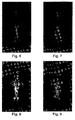
- FIGS. 6-9 show the dramatic improvement in image quality that has been obtained by using a cylindrical aperture instead of a planar aperture.
- the images from both planar and cylindrical systems were taken at between 90 to 100 GHz frequencies.
- the planar aperture images FIGS. 6 and 8 exhibited more shadows because the planar aperture width of 40 cm and depth of 60 cm corresponds to only 37° of angular coverage whereas the cylindrical aperture exhibited fewer shadows using 120° of 360° data FIGS. 7 and 9.
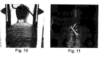
- FIG. 10 shows a photograph of a man with a concealed object and FIG. 11 shows the cylindrical image revealing the object, a Glock-17 handgun.
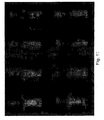
- FIG. 12 shows a mannequin with a small handgun taped to its back and covered with a cotton t-shirt, imaged over a 360° aperture. Eight of 64 view angles are shown in FIG. 12. Computer animation of the 64 view angles resulted in smooth animation of the images at frame rates of 4-32 frames per second. By observing the full animation, the target is viewed from all angles without requiring separate examination of a plurality of still images. The animation further preserves the three-dimensional nature of the target with concealed objects appearing "off" the target in several frames of the animation.
Landscapes
- Engineering & Computer Science (AREA)
- Physics & Mathematics (AREA)
- Remote Sensing (AREA)
- Health & Medical Sciences (AREA)
- Radar, Positioning & Navigation (AREA)
- Life Sciences & Earth Sciences (AREA)
- General Physics & Mathematics (AREA)
- Computer Networks & Wireless Communication (AREA)
- General Health & Medical Sciences (AREA)
- Molecular Biology (AREA)
- Veterinary Medicine (AREA)
- Public Health (AREA)
- Animal Behavior & Ethology (AREA)
- Surgery (AREA)
- Medical Informatics (AREA)
- Electromagnetism (AREA)
- Biophysics (AREA)
- Pathology (AREA)
- Biomedical Technology (AREA)
- Heart & Thoracic Surgery (AREA)
- Artificial Intelligence (AREA)
- Radiology & Medical Imaging (AREA)
- Psychiatry (AREA)
- Physiology (AREA)
- Theoretical Computer Science (AREA)
- Computer Vision & Pattern Recognition (AREA)
- Mathematical Physics (AREA)
- Geophysics (AREA)
- Signal Processing (AREA)
- Nuclear Medicine, Radiotherapy & Molecular Imaging (AREA)
- General Life Sciences & Earth Sciences (AREA)
- Radar Systems Or Details Thereof (AREA)
- Holo Graphy (AREA)
- Traffic Control Systems (AREA)
- Burglar Alarm Systems (AREA)
Claims (9)
- Holographische Vorrichtung zur annähernden Echtzeitabbildung eines Ziels, welche Vorrichtung eine Millimeterwellenstrahlung mit einer Vielzahl von Frequenzen von etwa 1 bis etwa 110 GHz verwendet, umfassend(a) eine holographische Anordnung bzw. Feld (10) mit einer Vielzahl von Antenneneinheiten, die etwa 0,25 bis etwa 3 Wellenlängen beabstandet sind, wobei jede Einheit eine Millimeterwellenstrahlung sendet und/oder empfängt und wobei die Anordnung von dem Ziel beabstandet ist;(b) einen holographischen Breitband-Sendeempfänger (12) zum Betreiben der Antenneneinheiten und zum Versorgen jeder Einheit mit einer Millimeterwellenstrahlungsquelle und zum anschließenden Empfangen einer Hochfrequenz-Millimeterwellenstrahlungsreflexion von dem Ziel und gesammelt durch die Einheit , und zum anschließenden Vornehmen einer Ausgabe;(c) einen Analog-Digital-Umsetzer (14) zum Umsetzen der Ausgabe in ein entsprechendes digitales Signal; und(d) einen Computer (16) zum Anwenden eines dreidimensionalen Rekonstruktionsalgorithmus auf das entsprechende digitale Signal, wobei eine unbegrenzte Tiefenschärfe erhalten bleibt, wobei die Verbesserung folgende Merkmale aufweist:
der Computer (16) ist ein digitaler Computer mit(i) einem ersten Befehlsvorrat bzw. -satz zum Empfangen von Daten von dem Analog-Digital-Umsetzer (14),(ii) einem zweiten Befehlsvorrat bzw. -satz zum Berechnen einer zweidimensionalen Fourier-Transformation der empfangenen Daten für jede Frequenz,(iii) einem dritten Befehlsvorrat bzw. -satz zum Multiplizieren der zweidimensionalen Fourier-Transformation mit einem Phasenfaktor und zum Berechnen einer eindimensionalen inversen Fourier-Transformation, gekennzeichnet durch:(iv) einen vierten Befehlsvorrat bzw. -satz zum Interpolieren der eindimensionalen inversen Fourier-Transformation auf ein gleichmäßig abgetastetes Raster und zum Bilden eines interpolierten Produkts,(v) einen fünften Befehlsvorrat bzw. -satz zum Berechnen einer dreidimensionalen inversen Transformation des interpolierten Produkts und zum Erhalten eines komplexen, zylindrischen, dreidimensionalen Bildes,(vi) einen sechsten Befehlsvorrat bzw. -satz zum Berechnen einer Größe des komplexen, zylindrischen, dreidimensionalen Bildes und zum Erhalten eines zylindrischen, dreidimensionalen Bildes, und(vii) einen siebten Befehlsvorrat bzw. -satz zum Anzeigen des zylindrischen dreidimensionalen Bildes. - Vorrichtung nach Anspruch 1, wobei die Antenneneinheiten (10) bistatisch bzw. mit je einer örtlich getrennten Sende- bzw. Empfangsantenne versehen sind.
- Vorrichtung nach Anspruch 1, wobei die Ausgabe eine gleichphasige Ausgabe ist.
- Vorrichtung nach Anspruch 1, wobei der erste Befehlsvorrat des Weiteren aufweist:einen untergeordneten Befehlsvorrat bzw. -satz zum Ableiten komplexer Daten (Q) von gleichphasigen Daten (I).
- Vorrichtung nach Anspruch 1, wobei die Anordnung (10) aufweist:eine lineare Anordnung, die während dem Senden und Empfangen der Hochfrequenz-Millimeterwellenstrahlung durch eine mechanische Einrichtung bewegt wird, wodurch ein gleichzeitiges Abtasten der Quelle und der Reflexion der Millimeterwellenstrahlung vorgesehen wird.
- Vorrichtung nach Anspruch 1, wobei der Sendeempfänger (12) ein bistatischer bzw. ein mit je einer örtlich getrennten Sende- bzw. Empfangsantenne versehener Überlagerungssendeempfänger mit gleichphasiger Ausgabe ist.
- Verfahren zur holographischen Überwachung eines Ziels, das folgende Schritte aufweist:(a) Abtasten einer zylindrischen Öffnung mit einer holographischen Anordnung (10) mit einer Vielzahl von Antenneneinheiten, die etwa 0,25 bis etwa 3 Wellenlängen beabstandet sind, wobei jede Einheit eine Millimeterwellenstrahlung sendet oder empfängt, und wobei die Anordnung von dem Ziel beabstandet ist;(b) Betreiben einzelner Antennenelemente mit einem holographischen Breitband-Sendeempfängersystem (12) und Versorgen jeder Einheit mit einer Breitband-Millimeterwellenstrahlungsquelle und anschließendes Empfangen einer Breitband-Millimeterwellenstrahlungsreflexion von dem Ziel und gesammelt durch die Einheit(en), und anschließendes Vornehmen einer Ausgabe,(c) Umsetzen der Ausgabe in ein entsprechendes digitales Signal in einem Analog-Digital-Umsetzer (14); und(d) Anwenden eines dreidimensionalen Rekonstruktionsalgorithmus auf das digitale Signal, wobei eine geringe Blendenzahl bzw. f-Zahl erhalten bleibt, durch folgende Schritte:(i) Empfangen von Daten vom Analog-Digital-Umsetzer,(ii) Berechnen einer zweidimensionalen Fourier-Transformation der empfangenen Daten für jede Frequenz,(iii) Multiplizieren der zweidimensionalen Fourier-Transformation mit einem Phasenfaktor und. Durchführen einer eindimensionalen inversen Fourier-Transformation und Bilden einer Inversion, gekennzeichnet durch(iv) Interpolieren der Inversion auf ein gleichmäßig abgetastetes Raster und Bilden eines interpolierten Produkts,(v) Berechnen einer dreidimensionalen inversen Transformation des interpolierten Produkts und Erhalten eines komplexen, dreidimensionalen Bildes,(vi) Berechnen einer Größe des komplexen, dreidimensionalen Bildes und Erhalten eines zylindrischen, dreidimensionalen Bildes, und(vii) Anzeigen des dreidimensionalen Bildes.
- Verfahren nach Anspruch 7, wobei das Anwenden des dreidimensionalen Rekonstruktionsalgorithmus das Anwenden einer Transformation zum Ableiten eines imaginären digitalen Signals zum Rekonstruieren eines holographischen Bildes umfasst.
- Verfahren nach Anspruch 7, wobei das Empfangen der Daten des Weiteren aufweist:Ableiten komplexer Daten (Q) von gleichphasigen Daten (I).
Applications Claiming Priority (3)
| Application Number | Priority Date | Filing Date | Title |
|---|---|---|---|
| US08/714,026 US5859609A (en) | 1991-08-30 | 1996-09-11 | Real-time wideband cylindrical holographic surveillance system |
| PCT/US1997/015723 WO1998011453A1 (en) | 1996-09-11 | 1997-09-05 | Real-time wideband cylindrical holographic surveillance system |
| US714026 | 2000-11-16 |
Publications (2)
| Publication Number | Publication Date |
|---|---|
| EP0925517A1 EP0925517A1 (de) | 1999-06-30 |
| EP0925517B1 true EP0925517B1 (de) | 2001-12-05 |
Family
ID=24868504
Family Applications (1)
| Application Number | Title | Priority Date | Filing Date |
|---|---|---|---|
| EP97939832A Expired - Lifetime EP0925517B1 (de) | 1996-09-11 | 1997-09-05 | Echtzeit-, breitband-, zylindrisches, holographisches überwachungssystem |
Country Status (10)
| Country | Link |
|---|---|
| US (1) | US5859609A (de) |
| EP (1) | EP0925517B1 (de) |
| JP (1) | JP3285881B2 (de) |
| AT (1) | ATE210305T1 (de) |
| AU (1) | AU4183597A (de) |
| CA (1) | CA2263539C (de) |
| DE (1) | DE69708890T2 (de) |
| ES (1) | ES2166559T3 (de) |
| IL (1) | IL128454A (de) |
| WO (1) | WO1998011453A1 (de) |
Cited By (4)
| Publication number | Priority date | Publication date | Assignee | Title |
|---|---|---|---|---|
| DE102005016106A1 (de) * | 2005-04-08 | 2006-10-19 | Smiths Heimann Gmbh | Verfahren und Vorrichtung zur Abbildung von Prüfobjekten mit Hilfe von Millimeterwellen, insbesondere zur Kontrolle von Personen auf verdächtige Gegenstände |
| US7609196B2 (en) | 2005-09-07 | 2009-10-27 | Smiths Heimann Gmbh | Method and device for imaging test objects by means of electromagnetic waves, in particular for inspecting individuals for suspicious items |
| CN105068126A (zh) * | 2015-07-02 | 2015-11-18 | 中国科学院上海微系统与信息技术研究所 | 一种带有幅度修正的毫米波全息成像方法 |
| US11570369B1 (en) | 2010-03-09 | 2023-01-31 | Stephen Michael Swinford | Indoor producing of high resolution images of the commonly viewed exterior surfaces of vehicles, each with the same background view |
Families Citing this family (103)
| Publication number | Priority date | Publication date | Assignee | Title |
|---|---|---|---|---|
| DE69928735T2 (de) * | 1998-09-14 | 2006-07-06 | Kabushiki Kaisha Toyota Chuo Kenkyusho, Nagakute | Holographisches Radar |
| US6777684B1 (en) | 1999-08-23 | 2004-08-17 | Rose Research L.L.C. | Systems and methods for millimeter and sub-millimeter wave imaging |
| US7068211B2 (en) * | 2000-02-08 | 2006-06-27 | Cambridge Consultants Limited | Methods and apparatus for obtaining positional information |
| US6507309B2 (en) | 2001-03-16 | 2003-01-14 | Battelle Memorial Institute | Interrogation of an object for dimensional and topographical information |
| US7405692B2 (en) | 2001-03-16 | 2008-07-29 | Battelle Memorial Institute | Detecting concealed objects at a checkpoint |
| US7365672B2 (en) * | 2001-03-16 | 2008-04-29 | Battelle Memorial Institute | Detection of a concealed object |
| US6876322B2 (en) * | 2003-06-26 | 2005-04-05 | Battelle Memorial Institute | Concealed object detection |
| US7248204B2 (en) * | 2001-09-28 | 2007-07-24 | Trex Enterprises Corp | Security system with metal detection and mm-wave imaging |
| GB0204167D0 (en) * | 2002-02-22 | 2002-04-10 | Qinetiq Ltd | Object detection apparatus and method |
| US7058439B2 (en) * | 2002-05-03 | 2006-06-06 | Contourmed, Inc. | Methods of forming prostheses |
| US6870791B1 (en) * | 2002-12-26 | 2005-03-22 | David D. Caulfield | Acoustic portal detection system |
| US6900438B2 (en) * | 2003-01-31 | 2005-05-31 | Millivision Technologies | Baseline compensating method and camera used in millimeter wave imaging |
| US6987560B2 (en) * | 2003-05-30 | 2006-01-17 | The Boeing Company | Inverse synthetic aperture radar-based covert system for human identification |
| JP2007510133A (ja) * | 2003-09-15 | 2007-04-19 | カウンシル フォー ザ セントラル ラボラトリーズ オブ ザ リサーチ カウンシルズ | ミリメートルおよびサブミリメートル撮像装置 |
| CA2543550C (en) * | 2003-10-30 | 2014-05-06 | Battelle Memorial Institute | Detection of a concealed object |
| US6992616B2 (en) * | 2003-12-05 | 2006-01-31 | Safeview, Inc. | Millimeter-wave active imaging system |
| US7119740B2 (en) * | 2003-12-05 | 2006-10-10 | Safeview, Inc. | Millimeter-wave active imaging system with modular array |
| US7212153B2 (en) * | 2003-12-05 | 2007-05-01 | Safeview, Inc. | Millimeter-wave active imaging system with fixed array |
| WO2005065090A2 (en) * | 2003-12-30 | 2005-07-21 | The Mitre Corporation | Techniques for building-scale electrostatic tomography |
| US20080174401A1 (en) * | 2004-04-14 | 2008-07-24 | L-3 Communications Security And Detection Systems, Inc | Surveillance of subject-associated items with identifiers |
| US7123185B2 (en) * | 2004-04-14 | 2006-10-17 | Safeview, Inc. | Enhanced surveilled subject imaging |
| US8350747B2 (en) | 2004-04-14 | 2013-01-08 | L-3 Communications Security And Detection Systems, Inc. | Surveillance with subject screening |
| US7205926B2 (en) * | 2004-04-14 | 2007-04-17 | Safeview, Inc. | Multi-source surveillance system |
| US7202808B2 (en) * | 2004-04-14 | 2007-04-10 | Safeview, Inc. | Surveilled subject privacy imaging |
| US7265709B2 (en) * | 2004-04-14 | 2007-09-04 | Safeview, Inc. | Surveilled subject imaging with object identification |
| US7180441B2 (en) * | 2004-04-14 | 2007-02-20 | Safeview, Inc. | Multi-sensor surveillance portal |
| US7973697B2 (en) * | 2004-04-14 | 2011-07-05 | L-3 Communications Security And Detection Systems, Inc. | Surveillance systems and methods with subject-related screening |
| US20050231416A1 (en) * | 2004-04-14 | 2005-10-20 | Rowe Richard L | Relational millimeter-wave interrogating |
| US8345918B2 (en) * | 2004-04-14 | 2013-01-01 | L-3 Communications Corporation | Active subject privacy imaging |
| US7053820B2 (en) * | 2004-05-05 | 2006-05-30 | Raytheon Company | Generating three-dimensional images using impulsive radio frequency signals |
| US7167091B2 (en) * | 2004-07-16 | 2007-01-23 | Safeview, Inc. | Vehicle activated millimeter-wave interrogating |
| US7253766B2 (en) * | 2004-09-24 | 2007-08-07 | Battelle Memorial Institute | Three-dimensional surface/contour processing based on electromagnetic radiation interrogation |
| US6967612B1 (en) * | 2004-10-22 | 2005-11-22 | Gorman John D | System and method for standoff detection of human carried explosives |
| US7386150B2 (en) * | 2004-11-12 | 2008-06-10 | Safeview, Inc. | Active subject imaging with body identification |
| US20060164286A1 (en) * | 2005-01-21 | 2006-07-27 | Safeview, Inc. | Frequency-based surveillance imaging |
| US7145506B2 (en) * | 2005-01-21 | 2006-12-05 | Safeview, Inc. | Depth-based surveillance image reconstruction |
| US7119731B2 (en) * | 2005-01-21 | 2006-10-10 | Safeview, Inc. | Depth-based surveillance imaging |
| WO2006080006A1 (en) * | 2005-01-26 | 2006-08-03 | Gamma Medica-Ideas (Norway) As | Video-rate holographic surveillance system |
| US7034746B1 (en) * | 2005-03-24 | 2006-04-25 | Bettelle Memorial Institute | Holographic arrays for threat detection and human feature removal |
| US7295146B2 (en) * | 2005-03-24 | 2007-11-13 | Battelle Memorial Institute | Holographic arrays for multi-path imaging artifact reduction |
| US8289199B2 (en) * | 2005-03-24 | 2012-10-16 | Agilent Technologies, Inc. | System and method for pattern design in microwave programmable arrays |
| US7327304B2 (en) * | 2005-03-24 | 2008-02-05 | Agilent Technologies, Inc. | System and method for minimizing background noise in a microwave image using a programmable reflector array |
| US20090294704A1 (en) * | 2005-06-08 | 2009-12-03 | Eitan Zailer | Active millimeter wave imaging system and method |
| US7855673B2 (en) | 2005-09-30 | 2010-12-21 | Battelle Memorial Institute | Holographic imaging of natural-fiber-containing materials |
| US7298317B2 (en) * | 2005-11-16 | 2007-11-20 | Intellifit Corporation | Gain compensation in an ultra-wideband transceiver |
| WO2007083479A1 (ja) * | 2006-01-23 | 2007-07-26 | Murata Manufacturing Co., Ltd. | レーダ装置 |
| DE102006006962A1 (de) * | 2006-02-14 | 2007-08-16 | Smiths Heimann Gmbh | Verfahren und Vorrichtung zur hochauflösenden Abbildung von Prüfobjekten mittels elektromagnetischer Wellen, insbesondere zur Kontrolle von Personen auf verdächtige Gegenstände |
| EP1877827A1 (de) * | 2006-03-24 | 2008-01-16 | Battelle Memorial Institute | Holographische arrays zur gefahrenerkennung und zur ausschaltung menschlicher funktionen |
| WO2008054865A2 (en) | 2006-04-26 | 2008-05-08 | L-3 Communications Security And Detection Systems, Inc. | Multi-source surveillance systems |
| US7844081B2 (en) * | 2006-05-15 | 2010-11-30 | Battelle Memorial Institute | Imaging systems and methods for obtaining and using biometric information |
| WO2008070788A2 (en) * | 2006-12-06 | 2008-06-12 | Kirsen Technologies Corporation | System and method for detecting dangerous objects and substances |
| US7773205B2 (en) * | 2007-06-06 | 2010-08-10 | California Institute Of Technology | High-resolution three-dimensional imaging radar |
| IL186884A (en) * | 2007-10-24 | 2014-04-30 | Elta Systems Ltd | Object simulation system and method |
| US20110102597A1 (en) * | 2008-02-14 | 2011-05-05 | Robert Patrick Daly | Millimeter Wave Concealed Object Detection System Using Portal Deployment |
| DE102008011350A1 (de) * | 2008-02-27 | 2009-09-03 | Loeffler Technology Gmbh | Vorrichtung und Verfahren zur Echtzeiterfassung von elektromagnetischer THz-Strahlung |
| US20100328142A1 (en) * | 2008-03-20 | 2010-12-30 | The Curators Of The University Of Missouri | Microwave and millimeter wave resonant sensor having perpendicular feed, and imaging system |
| US7746266B2 (en) * | 2008-03-20 | 2010-06-29 | The Curators Of The University Of Missouri | Microwave and millimeter wave imaging system |
| WO2009137528A1 (en) * | 2008-05-05 | 2009-11-12 | The Advantage Network, Llc | Microwave imaging system and method |
| EP2146327A1 (de) * | 2008-07-17 | 2010-01-20 | Nederlandse Organisatie voor toegepast- natuurwetenschappelijk onderzoek TNO | Elektromagnetisches Körperabtastsystem, Verfahren und Computerprogrammprodukt |
| US20100013920A1 (en) * | 2008-07-21 | 2010-01-21 | Safeview, Inc. | Surveillance imaging with upsampling |
| GB0816978D0 (en) * | 2008-09-17 | 2008-10-22 | Qinetiq Ltd | Security portal |
| DE102008059932A1 (de) * | 2008-12-02 | 2010-06-10 | Synview Gmbh | Vorrichtung und Verfahren zum Abbilden eines Objekts mit elektromagnetischer Hochfrequenzstrahlung |
| EP2204670B1 (de) * | 2008-12-23 | 2014-06-11 | Sony Corporation | Adaptives Messsystem |
| US7952515B2 (en) * | 2009-02-26 | 2011-05-31 | Mcewan Technologies, Llc | Range gated holographic radar |
| US8558734B1 (en) * | 2009-07-22 | 2013-10-15 | Gregory Hubert Piesinger | Three dimensional radar antenna method and apparatus |
| RU2411504C1 (ru) * | 2009-11-26 | 2011-02-10 | Общество с ограниченной ответственностью "Научно-технический центр прикладной физики" (ООО "НТЦ ПФ") | Способ дистанционного досмотра цели в контролируемой области пространства |
| RU2408005C1 (ru) * | 2009-11-26 | 2010-12-27 | Общество с ограниченной ответственностью "Научно-технический центр прикладной физики" (ООО "НТЦ ПФ") | Способ определения диэлектрической проницаемости диэлектрического объекта |
| JP5617292B2 (ja) * | 2010-03-23 | 2014-11-05 | 富士通株式会社 | 送受信装置およびイメージング装置 |
| JP2011259373A (ja) * | 2010-06-11 | 2011-12-22 | Sony Corp | 立体画像表示装置及び立体画像表示方法 |
| KR101700621B1 (ko) | 2010-12-15 | 2017-02-01 | 한국전자통신연구원 | 임의의 측정거리에 적용가능한 적응형 초고속 및 고해상도 3차원 영상복원 방법 |
| KR20120072048A (ko) * | 2010-12-23 | 2012-07-03 | 한국전자통신연구원 | 밀리미터파를 이용한 인체 치수 측정 장치 |
| CN103018738B (zh) * | 2011-09-20 | 2014-07-09 | 中国科学院电子学研究所 | 基于旋转天线阵列的微波三维成像方法 |
| CN102508240B (zh) * | 2011-10-30 | 2013-07-03 | 北京无线电计量测试研究所 | 毫米波主动式三维全息成像的人体安检系统的扫描方法 |
| WO2013074740A1 (en) | 2011-11-15 | 2013-05-23 | L-3 Communications Security And Detection Systems, Inc. | Millimeter-wave subject surveillance with body characterization for object detection |
| US9316732B1 (en) * | 2012-04-05 | 2016-04-19 | Farrokh Mohamadi | Standoff screening apparatus for detection of concealed weapons |
| CN103033522B (zh) * | 2012-12-14 | 2015-09-16 | 中国科学院深圳先进技术研究院 | 毫米波样品检测方法和系统 |
| FR3003959B1 (fr) * | 2013-04-02 | 2015-04-10 | Sas Sws | Antenne rotative, scanner utilisant une telle antenne, et dispositif de controle de personnes |
| JP2015132597A (ja) * | 2013-12-10 | 2015-07-23 | マスプロ電工株式会社 | ミリ波撮像装置 |
| US10942262B2 (en) | 2014-02-12 | 2021-03-09 | Battelle Memorial Institute | Shared aperture antenna array |
| ES2796098T3 (es) * | 2014-03-12 | 2020-11-25 | Kenjiro Kimura | Método de tomografía de dispersión y dispositivo de tomografía de dispersión |
| CN104536001B (zh) * | 2015-01-15 | 2017-01-18 | 云南航天工程物探检测股份有限公司 | 一种基于数据切片的圆柱形桥墩质量检测方法 |
| US10690760B2 (en) | 2015-05-05 | 2020-06-23 | Vayyar Imaging Ltd | System and methods for three dimensional modeling of an object using a radio frequency device |
| EP3358338B1 (de) * | 2015-09-29 | 2022-03-30 | National University Corporation Kobe University | Abbildungsverfahren und abbildungsvorrichtung |
| CN105388474B (zh) * | 2015-12-23 | 2018-05-25 | 同方威视技术股份有限公司 | 毫米波三维全息扫描成像设备及人体或物品检查方法 |
| CN105510912A (zh) * | 2015-12-25 | 2016-04-20 | 深圳市太赫兹科技创新研究院 | 基于毫米波全息三维成像的人体安检系统及方法 |
| CN105759269B (zh) * | 2016-04-25 | 2018-06-26 | 华讯方舟科技有限公司 | 三维全息成像的安检系统及方法 |
| CN105785368B (zh) * | 2016-04-29 | 2018-04-06 | 电子科技大学 | 一种基于视频sar的隐匿危险品探测方法 |
| CN106291732B (zh) * | 2016-08-18 | 2018-03-02 | 华讯方舟科技有限公司 | 基于毫米波成像的全方位安检系统 |
| CN106556874B (zh) * | 2016-10-31 | 2018-10-23 | 华讯方舟科技有限公司 | 一种近距离微波成像方法及系统 |
| US11412937B2 (en) * | 2017-03-29 | 2022-08-16 | Texas Instruments Incorporated | Multi-person vital signs monitoring using millimeter wave (mm-wave) signals |
| CN107132538A (zh) * | 2017-04-28 | 2017-09-05 | 华讯方舟科技有限公司 | 一种微波三维成像系统及方法 |
| CN109407165B (zh) * | 2018-03-09 | 2023-11-03 | 同方威视技术股份有限公司 | 可扩展式毫米波安检系统、扫描单元及对人体进行安全检查的方法 |
| WO2020023673A1 (en) * | 2018-07-24 | 2020-01-30 | Smiths Interconnect, Inc. | Standoff detection system |
| CN109581527B (zh) * | 2018-12-21 | 2020-11-27 | 济南爱我本克网络科技有限公司 | 双臂式毫米波成像系统转动机构的驱动装置和方法 |
| CN109613619B (zh) * | 2018-12-21 | 2020-11-17 | 济南爱我本克网络科技有限公司 | 单臂式毫米波成像系统转动机构的驱动装置和方法 |
| CN110146879B (zh) * | 2019-05-06 | 2021-08-17 | 河北华讯方舟太赫兹技术有限公司 | 圆盘式安检仪、成像方法、装置以及存储装置 |
| WO2021014536A1 (ja) * | 2019-07-22 | 2021-01-28 | 日本電気株式会社 | 検査システム、及び、検査方法 |
| CN111722211B (zh) * | 2020-06-09 | 2021-11-30 | 上海工物高技术产业发展有限公司 | 人体尺寸测量装置 |
| CN112305539B (zh) * | 2020-09-25 | 2023-11-21 | 北方工业大学 | 基于球面波分解的ArcSAR极坐标格式成像方法 |
| CN112379372B (zh) * | 2020-11-27 | 2024-08-23 | 杭州睿影科技有限公司 | 一种毫米波全息成像方法、装置、安检系统 |
| JP7567582B2 (ja) * | 2021-03-15 | 2024-10-16 | 株式会社Jvcケンウッド | 立体映像表示装置、立体映像表示方法およびプログラム |
| CN115343773B (zh) * | 2022-08-22 | 2025-04-18 | 欧必翼太赫兹科技(北京)有限公司 | 全息成像系统 |
| US12405368B2 (en) | 2022-10-04 | 2025-09-02 | Battelle Memorial Institute | Imaging systems and associated methods |
Family Cites Families (6)
| Publication number | Priority date | Publication date | Assignee | Title |
|---|---|---|---|---|
| US4991093A (en) * | 1985-08-21 | 1991-02-05 | Exxon Research And Engineering Company | Method for producing tomographic images using direct Fourier inversion |
| US4901084A (en) * | 1988-04-19 | 1990-02-13 | Millitech Corporation | Object detection and location system |
| US5170170A (en) * | 1991-08-13 | 1992-12-08 | State University Of New York | Radiation imaging utilizing data reconstruction to provide transforms which accurately reflect wave propagation characteristics |
| US5557283A (en) * | 1991-08-30 | 1996-09-17 | Sheen; David M. | Real-time wideband holographic surveillance system |
| US5455590A (en) * | 1991-08-30 | 1995-10-03 | Battelle Memorial Institute | Real-time holographic surveillance system |
| DE4413689C1 (de) * | 1994-04-20 | 1995-06-08 | Siemens Ag | Röntgencomputertomograph |
-
1996
- 1996-09-11 US US08/714,026 patent/US5859609A/en not_active Expired - Lifetime
-
1997
- 1997-09-05 DE DE69708890T patent/DE69708890T2/de not_active Expired - Lifetime
- 1997-09-05 CA CA002263539A patent/CA2263539C/en not_active Expired - Lifetime
- 1997-09-05 EP EP97939832A patent/EP0925517B1/de not_active Expired - Lifetime
- 1997-09-05 ES ES97939832T patent/ES2166559T3/es not_active Expired - Lifetime
- 1997-09-05 AT AT97939832T patent/ATE210305T1/de not_active IP Right Cessation
- 1997-09-05 IL IL12845497A patent/IL128454A/xx not_active IP Right Cessation
- 1997-09-05 AU AU41835/97A patent/AU4183597A/en not_active Abandoned
- 1997-09-05 JP JP51372298A patent/JP3285881B2/ja not_active Expired - Lifetime
- 1997-09-05 WO PCT/US1997/015723 patent/WO1998011453A1/en not_active Ceased
Cited By (5)
| Publication number | Priority date | Publication date | Assignee | Title |
|---|---|---|---|---|
| DE102005016106A1 (de) * | 2005-04-08 | 2006-10-19 | Smiths Heimann Gmbh | Verfahren und Vorrichtung zur Abbildung von Prüfobjekten mit Hilfe von Millimeterwellen, insbesondere zur Kontrolle von Personen auf verdächtige Gegenstände |
| US7609196B2 (en) | 2005-09-07 | 2009-10-27 | Smiths Heimann Gmbh | Method and device for imaging test objects by means of electromagnetic waves, in particular for inspecting individuals for suspicious items |
| US11570369B1 (en) | 2010-03-09 | 2023-01-31 | Stephen Michael Swinford | Indoor producing of high resolution images of the commonly viewed exterior surfaces of vehicles, each with the same background view |
| US11778328B2 (en) | 2010-03-09 | 2023-10-03 | Stephen Michael Swinford | Revolutionary apparatus producing high resolution images of the commonly viewed exterior surfaces of automobiles |
| CN105068126A (zh) * | 2015-07-02 | 2015-11-18 | 中国科学院上海微系统与信息技术研究所 | 一种带有幅度修正的毫米波全息成像方法 |
Also Published As
| Publication number | Publication date |
|---|---|
| ATE210305T1 (de) | 2001-12-15 |
| JP2001501304A (ja) | 2001-01-30 |
| WO1998011453A1 (en) | 1998-03-19 |
| EP0925517A1 (de) | 1999-06-30 |
| AU4183597A (en) | 1998-04-02 |
| US5859609A (en) | 1999-01-12 |
| IL128454A (en) | 2003-07-31 |
| IL128454A0 (en) | 2000-01-31 |
| DE69708890T2 (de) | 2002-08-29 |
| DE69708890D1 (de) | 2002-01-17 |
| ES2166559T3 (es) | 2002-04-16 |
| CA2263539A1 (en) | 1998-03-19 |
| CA2263539C (en) | 2004-11-23 |
| JP3285881B2 (ja) | 2002-05-27 |
Similar Documents
| Publication | Publication Date | Title |
|---|---|---|
| EP0925517B1 (de) | Echtzeit-, breitband-, zylindrisches, holographisches überwachungssystem | |
| US5557283A (en) | Real-time wideband holographic surveillance system | |
| US11715228B2 (en) | Imaging systems and related methods including radar imaging with moving arrays or moving targets | |
| Sheen et al. | Three-dimensional millimeter-wave imaging for concealed weapon detection | |
| US5455590A (en) | Real-time holographic surveillance system | |
| US8060339B2 (en) | Multistatic concealed object detection | |
| Amineh et al. | Real-Time Three-Dimensional Imaging of Dielectric Bodies Using Microwave/Millimeter Wave Holography | |
| EP0179073B1 (de) | Hybrides nichtangreifendes ultraschallbildsystem | |
| Sheen et al. | Combined illumination cylindrical millimeter-wave imaging technique for concealed weapon detection | |
| EP2545395A1 (de) | Höchstauflösender bildgebungsradar | |
| Song et al. | Fast factorized Kirchhoff migration algorithm for near-field radar imaging with sparse MIMO arrays | |
| Hamidi et al. | 3D near-field millimeter-wave synthetic aperture radar imaging | |
| Sheen et al. | Near-field millimeter-wave imaging for weapon detection | |
| WO1993005408A1 (en) | High resolution holographic surveillance system | |
| ES et al. | ECHTZEIT-, BREITBAND-, ZYLINDRISCHES, HOLOGRAPHISCHES ÜBERWACHUNGSSYSTEM SYSTEME DE SURVEILLANCE HOLOGRAPHIQUE CYLINDRIQUE A LARGE BANDE ET A TEMPS REEL | |
| Jouadé et al. | High resolution radar focusing using spectral estimation methods in wide-band and near-field configurations: Application to millimeter-wave near-range imaging | |
| CN112505639A (zh) | 一种毫米波收发装置、安检系统 | |
| Liu et al. | MIMO-SAR Image Antialiasing for Cascaded mmWave Radar Sensor | |
| Kim et al. | Ku-band 1D-MIMO FMCW Radar System for ISARBased 3D Near Field Imaging | |
| Essen et al. | A four-element 80-GHz luggage scanner based on the synthetic aperture radar principle | |
| Watanabe et al. | Microwave 3D imaging of near-field scatterers mutually coupled with an antenna array | |
| Zhao et al. | Research on ISAR far-field imaging algorithms | |
| Li | Image reconstruction of microwave tomograms | |
| Fernandes et al. | A comparison of experimental and modeled results of an active millimeter wave inverse synthetic aperture radar system used to perform standoff detection of person-borne improvised explosive devices | |
| Soumekh | Synthetic aperture echo imaging |
Legal Events
| Date | Code | Title | Description |
|---|---|---|---|
| PUAI | Public reference made under article 153(3) epc to a published international application that has entered the european phase |
Free format text: ORIGINAL CODE: 0009012 |
|
| 17P | Request for examination filed |
Effective date: 19990312 |
|
| AK | Designated contracting states |
Kind code of ref document: A1 Designated state(s): AT BE CH DE DK ES FI FR GB GR IE IT LI LU MC NL PT SE |
|
| GRAG | Despatch of communication of intention to grant |
Free format text: ORIGINAL CODE: EPIDOS AGRA |
|
| 17Q | First examination report despatched |
Effective date: 20010205 |
|
| GRAG | Despatch of communication of intention to grant |
Free format text: ORIGINAL CODE: EPIDOS AGRA |
|
| GRAH | Despatch of communication of intention to grant a patent |
Free format text: ORIGINAL CODE: EPIDOS IGRA |
|
| GRAH | Despatch of communication of intention to grant a patent |
Free format text: ORIGINAL CODE: EPIDOS IGRA |
|
| GRAA | (expected) grant |
Free format text: ORIGINAL CODE: 0009210 |
|
| AK | Designated contracting states |
Kind code of ref document: B1 Designated state(s): AT BE CH DE DK ES FI FR GB GR IE IT LI LU MC NL PT SE |
|
| PG25 | Lapsed in a contracting state [announced via postgrant information from national office to epo] |
Ref country code: NL Free format text: LAPSE BECAUSE OF FAILURE TO SUBMIT A TRANSLATION OF THE DESCRIPTION OR TO PAY THE FEE WITHIN THE PRESCRIBED TIME-LIMIT Effective date: 20011205 Ref country code: LI Free format text: LAPSE BECAUSE OF FAILURE TO SUBMIT A TRANSLATION OF THE DESCRIPTION OR TO PAY THE FEE WITHIN THE PRESCRIBED TIME-LIMIT Effective date: 20011205 Ref country code: GR Free format text: LAPSE BECAUSE OF FAILURE TO SUBMIT A TRANSLATION OF THE DESCRIPTION OR TO PAY THE FEE WITHIN THE PRESCRIBED TIME-LIMIT Effective date: 20011205 Ref country code: FI Free format text: LAPSE BECAUSE OF FAILURE TO SUBMIT A TRANSLATION OF THE DESCRIPTION OR TO PAY THE FEE WITHIN THE PRESCRIBED TIME-LIMIT Effective date: 20011205 Ref country code: CH Free format text: LAPSE BECAUSE OF FAILURE TO SUBMIT A TRANSLATION OF THE DESCRIPTION OR TO PAY THE FEE WITHIN THE PRESCRIBED TIME-LIMIT Effective date: 20011205 Ref country code: BE Free format text: LAPSE BECAUSE OF FAILURE TO SUBMIT A TRANSLATION OF THE DESCRIPTION OR TO PAY THE FEE WITHIN THE PRESCRIBED TIME-LIMIT Effective date: 20011205 Ref country code: AT Free format text: LAPSE BECAUSE OF FAILURE TO SUBMIT A TRANSLATION OF THE DESCRIPTION OR TO PAY THE FEE WITHIN THE PRESCRIBED TIME-LIMIT Effective date: 20011205 |
|
| REF | Corresponds to: |
Ref document number: 210305 Country of ref document: AT Date of ref document: 20011215 Kind code of ref document: T |
|
| REG | Reference to a national code |
Ref country code: CH Ref legal event code: EP |
|
| REG | Reference to a national code |
Ref country code: GB Ref legal event code: IF02 |
|
| REG | Reference to a national code |
Ref country code: IE Ref legal event code: FG4D |
|
| REF | Corresponds to: |
Ref document number: 69708890 Country of ref document: DE Date of ref document: 20020117 |
|
| PG25 | Lapsed in a contracting state [announced via postgrant information from national office to epo] |
Ref country code: SE Free format text: LAPSE BECAUSE OF FAILURE TO SUBMIT A TRANSLATION OF THE DESCRIPTION OR TO PAY THE FEE WITHIN THE PRESCRIBED TIME-LIMIT Effective date: 20020305 Ref country code: PT Free format text: LAPSE BECAUSE OF FAILURE TO SUBMIT A TRANSLATION OF THE DESCRIPTION OR TO PAY THE FEE WITHIN THE PRESCRIBED TIME-LIMIT Effective date: 20020305 Ref country code: DK Free format text: LAPSE BECAUSE OF FAILURE TO SUBMIT A TRANSLATION OF THE DESCRIPTION OR TO PAY THE FEE WITHIN THE PRESCRIBED TIME-LIMIT Effective date: 20020305 |
|
| REG | Reference to a national code |
Ref country code: ES Ref legal event code: FG2A Ref document number: 2166559 Country of ref document: ES Kind code of ref document: T3 |
|
| NLV1 | Nl: lapsed or annulled due to failure to fulfill the requirements of art. 29p and 29m of the patents act | ||
| REG | Reference to a national code |
Ref country code: CH Ref legal event code: PL |
|
| PG25 | Lapsed in a contracting state [announced via postgrant information from national office to epo] |
Ref country code: LU Free format text: LAPSE BECAUSE OF NON-PAYMENT OF DUE FEES Effective date: 20020905 Ref country code: IE Free format text: LAPSE BECAUSE OF NON-PAYMENT OF DUE FEES Effective date: 20020905 |
|
| PLBE | No opposition filed within time limit |
Free format text: ORIGINAL CODE: 0009261 |
|
| STAA | Information on the status of an ep patent application or granted ep patent |
Free format text: STATUS: NO OPPOSITION FILED WITHIN TIME LIMIT |
|
| 26N | No opposition filed | ||
| PG25 | Lapsed in a contracting state [announced via postgrant information from national office to epo] |
Ref country code: MC Free format text: LAPSE BECAUSE OF NON-PAYMENT OF DUE FEES Effective date: 20030401 |
|
| REG | Reference to a national code |
Ref country code: IE Ref legal event code: MM4A |
|
| REG | Reference to a national code |
Ref country code: FR Ref legal event code: PLFP Year of fee payment: 20 |
|
| PGFP | Annual fee paid to national office [announced via postgrant information from national office to epo] |
Ref country code: GB Payment date: 20160830 Year of fee payment: 20 Ref country code: IT Payment date: 20160914 Year of fee payment: 20 |
|
| PGFP | Annual fee paid to national office [announced via postgrant information from national office to epo] |
Ref country code: FR Payment date: 20160817 Year of fee payment: 20 |
|
| PGFP | Annual fee paid to national office [announced via postgrant information from national office to epo] |
Ref country code: ES Payment date: 20160830 Year of fee payment: 20 |
|
| PGFP | Annual fee paid to national office [announced via postgrant information from national office to epo] |
Ref country code: DE Payment date: 20160928 Year of fee payment: 20 |
|
| REG | Reference to a national code |
Ref country code: DE Ref legal event code: R071 Ref document number: 69708890 Country of ref document: DE |
|
| REG | Reference to a national code |
Ref country code: GB Ref legal event code: PE20 Expiry date: 20170904 |
|
| PG25 | Lapsed in a contracting state [announced via postgrant information from national office to epo] |
Ref country code: GB Free format text: LAPSE BECAUSE OF EXPIRATION OF PROTECTION Effective date: 20170904 |
|
| REG | Reference to a national code |
Ref country code: ES Ref legal event code: FD2A Effective date: 20180508 |
|
| PG25 | Lapsed in a contracting state [announced via postgrant information from national office to epo] |
Ref country code: ES Free format text: LAPSE BECAUSE OF EXPIRATION OF PROTECTION Effective date: 20170906 |