EP0924643A2 - Bilderzeugungsgerät und Verfahren zur Bilderzeugung - Google Patents
Bilderzeugungsgerät und Verfahren zur Bilderzeugung Download PDFInfo
- Publication number
- EP0924643A2 EP0924643A2 EP98310609A EP98310609A EP0924643A2 EP 0924643 A2 EP0924643 A2 EP 0924643A2 EP 98310609 A EP98310609 A EP 98310609A EP 98310609 A EP98310609 A EP 98310609A EP 0924643 A2 EP0924643 A2 EP 0924643A2
- Authority
- EP
- European Patent Office
- Prior art keywords
- processing
- image
- patch
- pixel
- patches
- Prior art date
- Legal status (The legal status is an assumption and is not a legal conclusion. Google has not performed a legal analysis and makes no representation as to the accuracy of the status listed.)
- Withdrawn
Links
Images


Classifications
-
- G—PHYSICS
- G06—COMPUTING OR CALCULATING; COUNTING
- G06T—IMAGE DATA PROCESSING OR GENERATION, IN GENERAL
- G06T1/00—General purpose image data processing
- G06T1/20—Processor architectures; Processor configuration, e.g. pipelining
-
- G—PHYSICS
- G06—COMPUTING OR CALCULATING; COUNTING
- G06F—ELECTRIC DIGITAL DATA PROCESSING
- G06F15/00—Digital computers in general; Data processing equipment in general
- G06F15/76—Architectures of general purpose stored program computers
- G06F15/80—Architectures of general purpose stored program computers comprising an array of processing units with common control, e.g. single instruction multiple data processors
Definitions
- the invention relates to an image creation apparatus, particularly to the acceleration of the drawing input processing.
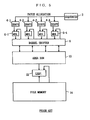
- FIGS. 5-7 An apparatus shown in FIGS. 5-7 as an example of concurrent processing.
- the drawing position is specified to the image on a monitor by a digitizer and so on, received at a sequencer 2, and is organized at a queue and so on. Then, a patch is divided into four, for example, and concurrent processing is carried out.
- Density data generators 4-1 to 4-4 for the brush used for drawing and multipliers 6-1 to 6-4 are placed in series at each drawing pipeline. High-speed access to an area RAM 10 is executed by a barrel shifter 8, and processing for a patch is carried out.
- the next patch is divided into four and processed.
- the high resolution image stored in a file memory 14 and an input image stored in the area RAM 10 are blended by a linear interpolator 12.
- the principle of drawing is to process a plurality of patches one by one in order. Processing data for pixels within a patch is read out from the area RAM 10, multiplied by the data of the density data generator 4 by the multiplier 6, and is rewritten into the area RAM 10. Since the plurality of patches overlap with each other, recursive operation for the same pixels at the area RAM 10 is carried out.
- each patch p1 - p3 is divided into four.
- the processing for a patch p1 is already executed and the processing for a patch p2 is being carried out.
- the patch p2 is divided into areas p2-1 to p2-4 shown at the bottom of the figure. Processing is completed up to area 16, while area 18 is yet to be processed in each area.
- FIG. 7 Processing for a stroke comprising patches pl-pn is shown in FIG. 7. Providing that four drawing pipelines are included, each patch is divided into four. The first area is processed at the first pipeline, the second area is processed at the second pipeline, and the third and the fourth areas are processed at the third and the fourth pipelines respectively. Each pipeline processes by the patch. Reading data from the area RAM and writing the result of the process (an access cycle in the figure) and mixing operation of input data and RAM data (a multiplication cycle) are carried out concurrently.
- the mixing operation during the drawing processing is accelerated by providing a plurality of drawing pipelines; however, the number of times for access to the area RAM 10 is not decreased. For example, if a patch comprises 10K pixels and if processing for 10 patches is necessary, the number of times for access to the area RAM 10 will be once each for reading and writing. Since access to each pixel is executed twice per patch, the total will be 200K, that is 10K x 10K x 2. Thus, there is a limit with concurrent processing, while the operation can be accelerated, since the number of times for access to a memory is not decreased. In a word, it is necessary not only to accelerate the operation during the drawing processing, but also to accelerate the access to the memory.
- the object of the invention at least in its preferred forms, is to decrease the number of times for access to a memory, and to simplify acceleration of drawing input processing.
- the image creation apparatus stores an image being created in a memory, displays the image on a monitor, receives drawing input data by a patch comprising a plurality of pixels in response to specification of a position on the displayed image. It is characterized by: a drawing pipeline including means for specifying a processing area comprising at least a pixel selected from a drawing area comprising a plurality of patches, and means for processing said processing area for said plurality of patches. According to the invention, it is not that a drawing area is processed by the patch, or the next patch is processed after processing for a patch is completed. It is rather that a plurality of patches are processed by the processing area comprising a few numbers of pixels, and the next processing area is processed after the above processing area is processed.
- a plurality of said drawing pipelines are provided, said processing area is divided spatially, allocated to, and processed concurrently by each drawing pipeline.
- said processing means includes a density data generator which generates drawing density data for a pixel by each patch placed in series, a multiplier, and a register, and said multiplier repeats the multiplication of the stored data of a register and the data of said density data generator for a plurality of patches.
- said processing area comprises a pixel
- said register comprises an accumulator
- the structure of a drawing pipeline is simplified. And one same pixel is processed for a number of patches repeatedly.
- a cache memory is connected to the output of said drawing pipeline and is utilized as a buffer between memory which stores an image and a drawing pipeline.
- the cache may be a small-size cache which can not store the whole allocated area.
- an image creation method storing an image being created in a memory, displaying the image on a monitor, specifying a position in the displayed image, and receiving drawing data input by a patch, characterized by:
- the processing for a next processing area is started after the processing for a former processing area which extends a plurality of patches but comprises at least a pixel is finished. For that reason, the number of times for access to the memory for each pixel in a drawing area is once for each reading and writing. The number of patches increases, but the number of times for access to the memory does not increase so much. As a result, the invention reduces the number of times for access to the memory, and drawing input is accelerated in terms of access according to the invention.
- a plurality of drawing pipelines are provided, and a drawing area is divided spatially and allocated to said plurality of drawing pipelines.
- the operation speed improves through concurrent processing, and the number of times for access to the memory is controlled not to increase since the processing is carried out by the processing area not by the patch.
- the drawing processing is executed at a high speed through concurrent operation, and the number of times for access is controlled not to increase so much.
- a register or an accumulator is provided at each drawing pipeline, density data of a few number of pixels is stored, and multiplication of the drawing density data and stored density data in the accumulator or the register is carried out repeatedly.
- Processing for a next pixel is executed after processing of a former pixel is completed for a plurality of patches with usage of the accumulator, or processing for next pixels is carried out after processing for a plurality of former pixels in the register are completed. Both steps of preparation of data for multiplication and the multiplication itself are operated concurrently, and the multiplication is carried out per pitch and by 1 stage at a high speed.
- a cache memory is connected to the output of each drawing pipeline. Writing into the cache is carried out each time the processing of a stroke for each pixel is finished for example.
- the total number of times for writing into the cache is about the number of pixels in a stroke. Even though the number of patches increases, since the number of times for writing does not increase, the processing will be simplified.
- the cache may be a small-size one which can not store data for pixels dealt with in a stroke, and thus, the hardware cost for an image creation apparatus will decrease.
- memories for high density images and low density images are provided, a plurality of drawing pipelines are provided. Pixels are processed according to the order in a drawing area not according to a patch order for the high resolution image, and processing by a patch order is executed for the low resolution image. Consequently, real-time processing to the low resolution image and high quality processing to the high resolution image are carried out.
- FIG. 1 is a fragmentary block diagram of the image creation apparatus of an embodiment .
- FIG. 2 is a diagram showing the allocation of a patch series to drawing pipelines in the embodiment.
- FIG. 3 is a diagram showing processing for each pixel.
- FIG. 4 is a flow chart showing algorithm of brush processing according to the embodiment.
- FIG. 5 is a fragmentary block diagram of an image creation apparatus of prior art.
- FIG. 6 is a diagram showing concurrent processing in another piece of prior art.
- FIG. 7 is a diagram showing processing of patches and access to an area RAM in drawing pipeline of prior art.
- the structure of the image creation apparatus is shown in FIG. 1, and drawing pipelines are indicated at 20; there are four pipelines in the embodiment.
- the drawing pipeline 20 comprises a queue 21 which is a first in first out queue, a sequencer 22 which processes an appropriate number of patches stored in the queue 21, for example, those comprising one stroke and the sequencer also deletes a patch series from the queue 21 after processing, a density data generator 23 which outputs an input density complement k to drawing input data, a multiplier 24, an accumulator 25, and a cache 26.
- a register for example having a capacity not more than 16 or 64 pixels, may be used as a substitute for the accumulator 25.
- a circular brush form in a patch which determines the density according to the distance from the center of the circle with a one dimensional density table is usable for the density data generator 23.
- Two dimensional brush form in a RAM which determines the RAM data as the density is also usable for the density data generator 23.
- pressure or the like to a stylus or a digitizer for drawing input is usable in the density data generator 23.
- Each caches 26 have the capacity for 1 K pixels for example, and the total capacity of the four caches is smaller than a drawing area which corresponds to one stroke.
- Two dimensional brushes have been widely used for image creation apparatuses.
- brush data is easily read out according to the relative address to an appropriate base position in the brush, such as the center of the brush. Therefore, according to prior art, the brush data is read out with incrementing the relative address one by one by an address counter.
- many pixels are processed as they come in, and a next patch is not processed until all pixels in a previous patch are processed.
- the processing is carried out pixel by pixel, not patch by patch, and the same pixel in a stroke is processed consecutively. For that reason, the relative address of a pixel to the base position in the brush is not constant between patches, and an address operation itself becomes complicated.
- the drawing processing is accelerated by multiplying the data of the accumulator and so on by the compliment repeatedly, i.e. since the data of the accumulator or the register is multiplied by the density data of the same pixel at the next patch, two bus cycles for reading from and writing into the memory become unnecessary. Therefore, density operation is carried out according to the speed of the multiplier 24, and there is no factors to slow down the processing speed due to the memory access.
- Indicated at 30 is a front-end processor which receives input from a digitizer and a stylus.
- the stylus specifies an input position according to the monitor coordinate system by specifying the position in the displayed image on a monitor 46 through a cursor and so on.
- the front-end processor 30 also manages a menu and so on, converts a drawing position specified by the monitor coordinate system into a coordinate according to a coordinate system for the whole stored image, and outputs data for specifying the kind of brush used and brush color at the same time.
- Kinds of brushes are chalk, crayon, oil painting and so on, and sizes of the brushes correspond to sizes of patches.
- a patch is a unit of drawing area specified by one touch of the stylus on the image and so on, and drawing is done by renewing stored data of pixels within a patch according to the brush color.
- a stroke comprises a plurality of patches, and in the embodiment, drawing onto a high resolution image is processed by the stroke.
- a patch size is, for example, about 10 K pixels, that is 100 pixels x 100 pixels, and changes depending on the kinds of brushes or pressure when pressure to the stylus is used for the determination of brush sizes.
- the first in first out queue 21 stores the data about patch series inputted which includes the center coordinates of the patches, the kind of selected brush, and the size.
- the sequencer 22 controls the drawing pipeline comprising the density data generator 23 to the cache 26. In this process, one pixel is chosen out of a drawing area stored in the queue which includes a plurality of patches and comprises one stroke, and the next pixel is processed in the same manner after the process for the above chosen pixel is completed for the all patches. Coordinates of the pixel to be processed, the center coordinate, size, and kind of the brush used are provided from the sequencer 22 to the density data generator 23. Writing into the cache 26 is carried out immediately before the start of processing of the next pixel, and output from the cache 26 are controlled by the sequencer 22.
- the density data generator 23 has means for generating data corresponding to the density distribution of the brush and means for generating data corresponding to the relative position of a pixel being processed within the brush, for example, the position from the center of the brush, as the relative address of the pixel being processed within the brush and so on.
- a two dimensional table is used as a data source regarding the density distribution of the brush, and also provided that the influence of the brush pressure is ignored for simplicity.
- Tables of this sort are, for example, stored brush by brush in another unshown memory. Each time the kind of brush is specified, one of the tables is selected and stored in the density data generator 23 temporarily. During a stroke the kind of brush is fixed.
- the coordinates of the pixel being processed is specified by the sequencer 22, and the position of the brush is changed by the patch, but according to the embodiment, this means the change in the relative address of the pixel being processed within the brush. Then the relative address is calculated patch by patch, the density data of the pixel being processed is read out from the table of the density data of the brush, and they are inputted to the multiplier 24.
- the data of density distribution of a brush is, for example, one dimensional, the center position of the brush and so on, is provided by the sequencer 22 patch by patch to the density data generator 23, and the density is calculated patch by patch according to the distance of the pixel being processed from the center of the brush and so on.
- the relative address of the pixel being processed from the center of the brush is modified according to the pressure, since it is a hard burden on the density data generator 23 to translate the data of density distribution of the brush by each patch and to restore them, according to the changes in pressure.
- output density of the density data generator 23 is obtained by modifying the density ignoring the pressure according to the pressure.
- the complements of density data within a stroke are stored in four caches 26 when a stroke is divided into four areas.
- Density data shows contribution of a color signal Q by drawing input
- a complement number of the density data shows contribution of a color signal P of an original image which is stored in a high resolution memory 32 before the drawing input.
- the color signal Q in the front-end processor 30 and the color signal P at the high resolution memory 32 are linearly interpolated with a linear interpolator 34 with usage of the complement of the density data at the cache 26, and this interpolation itself is known.
- the image in the high resolution memory 32 is outputted to a printer or an exterior disk which is not indicated.
- the resolution is reduced by a reduction means 36 and is inputted to a low resolution memory 38.
- a density data generator 40 for low resolution and a linear interpolator 42 are provided between the front-end processor 30 and the low resolution memory 38.
- the number of pixels in a patch are decreased to, for example, 1/4 x 1/4 that is 1/16, and the image in the low resolution memory 38 and the input image are linearly interpolated patch by patch.
- Drawing input processing for the high resolution memory 32 may be late from drawing input processing for the low resolution memory 38.
- the image in the high resolution memory 32 is reduced in size by the reduction means 36, for example, after drawing input is processed, and is written into the low resolution memory 38 over a previous image.
- a frame memory and the monitor are shown at 44 and 46 respectively.
- the frame memory 44 is not necessarily to be provided.
- the divided areas are shown in FIG. 2. Providing that a stroke comprises nine patches; the first patch is patch p1 and the last patch is patch p9, drawing input processing for the high resolution memory 32 is executed after a stroke input.
- the total drawing areas of patches p1-p9 are determined and divided into four, for example, after patches p1-p9 for a stroke are specified. Those areas are labeled as divided areas 50-53 and allocated to four drawing pipelines 20 per area.
- Processing at the divided area 50 is shown in FIG. 3. Processing in other divided areas is carried out in the same manner.
- Data for specifying each patch in a patch series for the divided area 50 such as the center position of each patch, kind of brush, and patch size are stored in the queue 21.
- the sequencer 22 cuts out a patch series in a way that the patches for a stroke are processed as a whole.
- the sequencer 22 processes one pixel at a time following spatial order, or the scan order in the divided area 50.
- the input order for patch p1 - p9 has no meaning. It is not that the next patch is processed after a patch is processed. Patches within a stroke are processed consecutively for a pixel in each divided area, and the next pixel in the area is processed after the former pixel is processed.
- the processing for one pixel is completed when the processing is repeated as many times as the number of patches, and the density complement at this moment is k1 x k2 x ... kn.
- the number is written in the cache 26, and the next pixel is processed in the same manner.
- the processing mentioned above is executed in four divided areas concurrently.
- the color signal P of the original image in the high resolution memory 32 and the color signal Q of the drawing input are linearly interpolated by the linear interpolator 34, for example, from the pixel already processed or from the pixel series already processed.
- the size of the cache 26 is small, the data sent to the cache 26 is processed by the linear interpolator 34, and the portion already processed is allocated to the next pixel immediately.
- the total size of the caches for the four drawing pipelines is smaller than the area RAM 10 in FIG. 5. Since there is no need for a fast large memory, the cost for the hardware will decrease.
- FIG. 4 shows functions of the embodiment.
- the drawing processing here a brush sub-routine, is started when the front-end processor receives drawing input.
- Drawing input generally specifies positions of patches and the color of the brush which is common among the patches.
- the front-end processor 30 instructs a linear-interpolator 42 to process drawing input at low resolution, and the linear-interpolator modifies the image in the low resolution memory 38, and displays the image on the monitor 46; therefore real-time response with low resolution is achieved.
- Processing for the low resolution memory 38 has been known, and it is not necessary to provide parallel drawing pipelines for the low resolution memory 38.
- the front end processor 30 divides an area for a stroke spatially, for example, into four and allocates them to the drawing pipelines as the divided areas 50 - 53 shown in FIG. 2.
- the first in first out queue 21 stores data for each patch (step 60), processes for a stroke one pixel at a time according to the scan order in the divided area (step 61), and controls the output into the cache 26 after the completion of a pixel. Processes for steps 60, 61, 62 are carried out concurrently at the four drawing pipelines.
- linear-interpolation is conducted between a color signal P for the pixel in the high resolution memory 32 and a color signal Q by the linear interpolator 34.
- processing for low resolution image for example, is carried out and then displayed on the monitor 46.
- the image in the high resolution memory 32 is reduced in size and is written into the low resolution memory 38, for example, after the completion of processing of a stroke at high resolution.
- the sequencer 22 deletes a patch series already processed from the queue 21 and instructs the processing for the next stroke.
- operation speed will be four times as fast since four drawing pipelines 20 are provided.
- data of the accumulator 25 is used repeatedly, the operation is carried out at a high speed.
- reading a density data from the density data generator 23 and writing the multiplication result by the multiplier 24 to the accumulator 25, are carried out concurrently, reading, multiplication, and writing operations can be carried out in a pitch, and time when the multiplier 24 is waiting is not necessary.
- writing into the cache 26 is executed once for each pixel in a stroke.
- both reading and writing for each pixel in the drawing area are executed once for a stoke. For example, providing that patch size is 10K, if a stylus is moved through a stroke at a distance of about a diameter of a patch, the drawing area will be approximately 20K pixels. So, writing into each cache 26 will be executed 5K times, and reading and writing into the high resolution memory 32 will be executed approximately 20K times each. For example, approximately 1K pixels is enough for the size of each cache 26, and small cache 26 can be used.
- reading and writing will be carried out from and to the area RAM 10 100K times, that is 10K x 10, and the number of times for access to the memory is four times of the embodiment.
- the embodiment is equivalent to one using a 4-times faster memory and a bus, and a 2-times faster multiplier. For that reason, if the drawing pipelines are reinforced, drawing input processing will be accelerated up to an arbitrary speed actually.
- the area RAM 10 over the size of a stroke is necessary, but in the embodiment, only four small caches 26 are necessary.
- a register with the size of 16 pixels or 64 pixels which deals with pixels in a next patch after processing pixels of the size of the register in a present patch is equivalent to the accumulator 25.
- a register and an accumulator are expensive memories and the accumulator 25 is most convenient and preferable.
- the sequencer 22 divides the stroke into a number of sub-strokes each of which have patches suitable to be processed by the drawing pipelines, for example 10 patches, and processes the sub-strokes.
- the sequencer 22 processes a new stroke after processing the former stroke. Furthermore, it is acceptable to divide a stroke into, for example, two sub-strokes and process the divided sub-strokes one by one.
- the processing of a 2D image is shown, but the present invention is applicable to the processing of a 3D image.
- a texture image, etc. of a 3D image. is stored in a high resolution memory. It is also acceptable to divide the high resolution memory 32 into many planes, and process an image in the specified plane.
Landscapes
- Engineering & Computer Science (AREA)
- Theoretical Computer Science (AREA)
- Physics & Mathematics (AREA)
- General Physics & Mathematics (AREA)
- Computer Hardware Design (AREA)
- Computing Systems (AREA)
- General Engineering & Computer Science (AREA)
- Image Processing (AREA)
- Image Generation (AREA)
- Processing Or Creating Images (AREA)
Applications Claiming Priority (2)
| Application Number | Priority Date | Filing Date | Title |
|---|---|---|---|
| JP36579697 | 1997-12-22 | ||
| JP36579697 | 1997-12-22 |
Publications (2)
| Publication Number | Publication Date |
|---|---|
| EP0924643A2 true EP0924643A2 (de) | 1999-06-23 |
| EP0924643A3 EP0924643A3 (de) | 2001-01-24 |
Family
ID=18485139
Family Applications (1)
| Application Number | Title | Priority Date | Filing Date |
|---|---|---|---|
| EP98310609A Withdrawn EP0924643A3 (de) | 1997-12-22 | 1998-12-22 | Bilderzeugungsgerät und Verfahren zur Bilderzeugung |
Country Status (3)
| Country | Link |
|---|---|
| US (1) | US6329995B1 (de) |
| EP (1) | EP0924643A3 (de) |
| KR (1) | KR19990063174A (de) |
Families Citing this family (4)
| Publication number | Priority date | Publication date | Assignee | Title |
|---|---|---|---|---|
| US7511703B2 (en) * | 2004-06-28 | 2009-03-31 | Microsoft Corporation | Using size and shape of a physical object to manipulate output in an interactive display application |
| US7646377B2 (en) * | 2005-05-06 | 2010-01-12 | 3M Innovative Properties Company | Position digitizing using an optical stylus to image a display |
| US8885208B2 (en) * | 2006-07-21 | 2014-11-11 | Adobe Systems Incorporated | Progressive refinement of an edited image using secondary high resolution image processing |
| TWI493399B (zh) * | 2012-10-30 | 2015-07-21 | Mstar Semiconductor Inc | 觸控座標邊緣效應校正的方法與相關系統 |
Family Cites Families (11)
| Publication number | Priority date | Publication date | Assignee | Title |
|---|---|---|---|---|
| GB8425531D0 (en) | 1984-10-10 | 1984-11-14 | Quantel Ltd | Video image creation |
| EP0202014B1 (de) | 1985-04-13 | 1996-02-28 | Quantel Limited | Videobildgestaltungssysteme |
| US5357265A (en) * | 1989-04-17 | 1994-10-18 | Quantel Limited | Electronic graphic system |
| GB8908612D0 (en) * | 1989-04-17 | 1989-06-01 | Quantel Ltd | Video graphics system |
| JPH08101922A (ja) | 1991-01-07 | 1996-04-16 | Shima Seiki Mfg Ltd | 画像編集作成装置および画像編集作成方法 |
| GB2267203B (en) * | 1992-05-15 | 1997-03-19 | Fujitsu Ltd | Three-dimensional graphics drawing apparatus, and a memory apparatus to be used in texture mapping |
| DE69332379T2 (de) * | 1993-11-23 | 2003-07-10 | Hewlett-Packard Co. (N.D.Ges.D.Staates Delaware), Palo Alto | Tintenwiedergabe |
| US5592597A (en) * | 1994-02-14 | 1997-01-07 | Parametric Technology Corporation | Real-time image generation system for simulating physical paint, drawing media, and feature modeling with 3-D graphics |
| US5701405A (en) * | 1995-06-21 | 1997-12-23 | Apple Computer, Inc. | Method and apparatus for directly evaluating a parameter interpolation function used in rendering images in a graphics system that uses screen partitioning |
| US5912673A (en) * | 1995-11-27 | 1999-06-15 | Sun Microsystems, Inc. | Graphical image convolution using multiple pipelines |
| GB2317089B (en) * | 1996-09-06 | 2001-05-16 | Quantel Ltd | An electronic graphic system |
-
1998
- 1998-12-18 KR KR1019980055934A patent/KR19990063174A/ko not_active Withdrawn
- 1998-12-21 US US09/216,848 patent/US6329995B1/en not_active Expired - Fee Related
- 1998-12-22 EP EP98310609A patent/EP0924643A3/de not_active Withdrawn
Also Published As
| Publication number | Publication date |
|---|---|
| US6329995B1 (en) | 2001-12-11 |
| KR19990063174A (ko) | 1999-07-26 |
| EP0924643A3 (de) | 2001-01-24 |
Similar Documents
| Publication | Publication Date | Title |
|---|---|---|
| EP0403054B1 (de) | Elektronisches graphisches System | |
| US8339409B2 (en) | Tile-based graphics system and method of operation of such a system | |
| US5745739A (en) | Virtual coordinate to linear physical memory address converter for computer graphics system | |
| JPS6163165A (ja) | ビデオ信号処理装置 | |
| GB2246931A (en) | Computer graphics | |
| US20040012611A1 (en) | Anti-aliasing interlaced video formats for large kernel convolution | |
| JPS6191777A (ja) | ビデオ画像形成装置 | |
| JP3058017B2 (ja) | グラフィックス画素データを変換するための装置および方法 | |
| US6329995B1 (en) | Image creation apparatus and image creation method | |
| US5321805A (en) | Raster graphics engine for producing graphics on a display | |
| EP0905652A2 (de) | Bildverarbeitungsvorrichtung | |
| KR101311311B1 (ko) | 프로그래밍 가능한 데이터 처리 회로 | |
| US7126604B1 (en) | Efficiently determining storage locations for the levels of detail of a MIP map of an image | |
| JP3047009B2 (ja) | 画像作成装置及び画像作成方法 | |
| JP2813881B2 (ja) | ビデオ信号処理装置 | |
| US6125437A (en) | Virtual linear frame buffer addressing method and apparatus | |
| JP2854420B2 (ja) | 多次元アドレス発生器およびその制御方式 | |
| US7769247B2 (en) | Method and apparatus for data re-arrangement | |
| JP2002366962A (ja) | 描画装置及び描画方法 | |
| JP3358891B2 (ja) | Z値の透視変換処理方法及び画像処理装置 | |
| JPH07303650A (ja) | Ip処理方法及びip処理装置 | |
| JPH0480428B2 (de) | ||
| JPH0750448B2 (ja) | 配列添字変換装置 | |
| JPH0962853A (ja) | グラフィックプロセッサ及びグラフィック処理システム | |
| JPH08194641A (ja) | 同期dramへの2次元データ格納方法および同期dramアクセス制御装置 |
Legal Events
| Date | Code | Title | Description |
|---|---|---|---|
| PUAI | Public reference made under article 153(3) epc to a published international application that has entered the european phase |
Free format text: ORIGINAL CODE: 0009012 |
|
| AK | Designated contracting states |
Kind code of ref document: A2 Designated state(s): DE FR GB IT |
|
| AX | Request for extension of the european patent |
Free format text: AL;LT;LV;MK;RO;SI |
|
| PUAL | Search report despatched |
Free format text: ORIGINAL CODE: 0009013 |
|
| AK | Designated contracting states |
Kind code of ref document: A3 Designated state(s): AT BE CH CY DE DK ES FI FR GB GR IE IT LI LU MC NL PT SE |
|
| AX | Request for extension of the european patent |
Free format text: AL;LT;LV;MK;RO;SI |
|
| 17P | Request for examination filed |
Effective date: 20010319 |
|
| 17Q | First examination report despatched |
Effective date: 20010530 |
|
| AKX | Designation fees paid |
Free format text: DE FR GB IT |
|
| GRAP | Despatch of communication of intention to grant a patent |
Free format text: ORIGINAL CODE: EPIDOSNIGR1 |
|
| STAA | Information on the status of an ep patent application or granted ep patent |
Free format text: STATUS: THE APPLICATION IS DEEMED TO BE WITHDRAWN |
|
| 18D | Application deemed to be withdrawn |
Effective date: 20040622 |