EP0923974B1 - Gas-liquid separator - Google Patents
Gas-liquid separator Download PDFInfo
- Publication number
- EP0923974B1 EP0923974B1 EP98928559A EP98928559A EP0923974B1 EP 0923974 B1 EP0923974 B1 EP 0923974B1 EP 98928559 A EP98928559 A EP 98928559A EP 98928559 A EP98928559 A EP 98928559A EP 0923974 B1 EP0923974 B1 EP 0923974B1
- Authority
- EP
- European Patent Office
- Prior art keywords
- gas
- cylindrical container
- air
- receiving plate
- liquid separator
- Prior art date
- Legal status (The legal status is an assumption and is not a legal conclusion. Google has not performed a legal analysis and makes no representation as to the accuracy of the status listed.)
- Expired - Lifetime
Links
- 239000007788 liquid Substances 0.000 title claims abstract description 80
- 238000005192 partition Methods 0.000 claims abstract description 33
- 238000000926 separation method Methods 0.000 claims abstract description 25
- 238000007599 discharging Methods 0.000 claims abstract description 20
- 230000007246 mechanism Effects 0.000 claims description 5
- 230000008859 change Effects 0.000 abstract description 5
- XLYOFNOQVPJJNP-UHFFFAOYSA-N water Chemical compound O XLYOFNOQVPJJNP-UHFFFAOYSA-N 0.000 description 25
- 230000005484 gravity Effects 0.000 description 9
- 238000007664 blowing Methods 0.000 description 7
- 230000000694 effects Effects 0.000 description 6
- 239000012530 fluid Substances 0.000 description 6
- 239000002245 particle Substances 0.000 description 5
- 239000002826 coolant Substances 0.000 description 4
- 238000000034 method Methods 0.000 description 3
- 230000008569 process Effects 0.000 description 3
- 230000004888 barrier function Effects 0.000 description 2
- 238000001816 cooling Methods 0.000 description 2
- 230000000630 rising effect Effects 0.000 description 2
- 238000010276 construction Methods 0.000 description 1
- 230000001419 dependent effect Effects 0.000 description 1
- 238000001035 drying Methods 0.000 description 1
- 239000000428 dust Substances 0.000 description 1
- 230000007613 environmental effect Effects 0.000 description 1
- 238000003780 insertion Methods 0.000 description 1
- 230000037431 insertion Effects 0.000 description 1
- 230000002093 peripheral effect Effects 0.000 description 1
- 229920006395 saturated elastomer Polymers 0.000 description 1
Images


Classifications
-
- B—PERFORMING OPERATIONS; TRANSPORTING
- B01—PHYSICAL OR CHEMICAL PROCESSES OR APPARATUS IN GENERAL
- B01D—SEPARATION
- B01D45/00—Separating dispersed particles from gases or vapours by gravity, inertia, or centrifugal forces
- B01D45/12—Separating dispersed particles from gases or vapours by gravity, inertia, or centrifugal forces by centrifugal forces
- B01D45/16—Separating dispersed particles from gases or vapours by gravity, inertia, or centrifugal forces by centrifugal forces generated by the winding course of the gas stream, the centrifugal forces being generated solely or partly by mechanical means, e.g. fixed swirl vanes
-
- B—PERFORMING OPERATIONS; TRANSPORTING
- B01—PHYSICAL OR CHEMICAL PROCESSES OR APPARATUS IN GENERAL
- B01D—SEPARATION
- B01D45/00—Separating dispersed particles from gases or vapours by gravity, inertia, or centrifugal forces
- B01D45/04—Separating dispersed particles from gases or vapours by gravity, inertia, or centrifugal forces by utilising inertia
- B01D45/08—Separating dispersed particles from gases or vapours by gravity, inertia, or centrifugal forces by utilising inertia by impingement against baffle separators
Definitions
- the present invention relates to a gas-liquid separator for removing a liquid, such as moisture, contained in gas including high-pressure air.
- an air dehumidifier using a coolant such as chlorofluorocarbons.
- a coolant such as chlorofluorocarbons
- Such an air dehumidifier has environmental problems due to the use of a coolant, for example, chlorofluorocarbons, and also requires additional devices such as a compressor or condenser for compressing the coolant and a heat exchanger for cooling the high-pressure air.
- a running cost is relatively high because a power source for operating those devices is necessary.
- moisture in high-pressure air is removed by passing the high-pressure air through a filter provided in a dehumidifier body.
- This dehumidifier has a problem that if the filter becomes moist during use, moisture that has been put on the filter with the high-pressure air passing through the filter is extruded to the rear surface of the filter, causing the dehumidified high-pressure air to be moistened again. If the filter is saturated with moisture, such a problem is more serious, and the dehumidifying effect is so reduced that the filter has to be cleaned and replaced periodically.
- the proposed dehumidifier comprises an air introducing passage and a discharging passage provided respectively to the lower and upper parts of a side surface of a cylindrical body having a hollow chamber therein, a collision surface disposed at a position in front of the introducing passage for collision of air, and a guide part for changing a flow of air that has collided with the collision surface. Further, a conical receiving plate with an opening formed at the center thereof is arranged in the hollow chamber, and a barrier plate having air holes formed therein is provided above the receiving plate.
- the proposed dehumidifier compressed air introduced to the hollow chamber through the introducing passage violently collides with the collision surface, whereby moisture contained in the compressed air is turned into water drops. Also, the air is changed in direction substantially at a right angle so that the air is released into the hollow chamber to follow an inner surface of the hollow chamber. The released air is separated into moisture having large specific gravity and air having small specific gravity due to centrifugal force under whirling. The separated moisture is dropped and received by a drain, and only dehumidified air is discharged through the discharging passage.
- the proposed dehumidifier can efficiently remove moisture in air without using the devices conventionally employed, e.g., a compressor or the like to produce power, and an air filter which needs to be replaced.
- WO-A-96 27423 discloses a mechanical fluid separator which defines an interior chamber for centrifugally separating entrained media from a fluid stream.
- the mechanical fluid separator has a fluid inlet connecting the interior chamber with the media entrained fluid source.
- a cone-shaped buffle disposed within the mechanical fluid separator defines a conical surface having a concave surface and a convex surface.
- the basic principle of a dehumidifier proposed in the above Japanese Unexamined Patent Publication No. Hei 8-290028 resides in violently colliding gas which contains moisture with the collision surface to turn the moisture into water drops, and whirling the gas at a high speed for centrifugal separation into gas and liquid.
- the present invention provides a gas-liquid separator wherein a gas inlet port is provided in the side surface of a cylindrical container having a hollow chamber formed therein, a discharging port for discharging gas after gas-liquid separation is provided at the top of the cylindrical container, a collision surface with which gas supplied from the gas inlet port collides and a guide part for changing a flow direction of the gas after collision so as to flow along an inner wall surface of the cylindrical container in a circumferential direction are provided in the cylindrical container at a position to face the gas inlet port, a receiving plate having a substantially conical shape with an opening formed at a center thereof is provided in an upper portion of the hollow chamber with a projecting central portion faced downward to divide the hollow chamber into upper and lower hollow chambers, the upper hollow chamber partitioned by the receiving plate is communicated with the discharging port, and a partition having at least one venthole and dividing the upper hollow chamber is disposed above the receiving plate in opposed relation, said collision surface being curved to follow an inner wall surface of the cylindrical container
- the above problem is solved by forming a collision surface to have a curved shape following an inner wall surface of the cylindrical container, or to incline so as to widen a flow passage toward the downstream side.
- curved shape following an inner wall surface of the cylindrical containers means such a shape as allowing the gas, which is released from the guide part to the vicinity of the inner wall surface of the cylindrical container, to flow without colliding with the wall of the cylindrical container and to whirl along the inner wall surface thereof.
- the collision surface In the case of inclining the collision surface, the inclination must meet both requirements of permitting the separation into gas and liquid upon collision and reducing energy loss caused when the flow direction of the gas is changed after the collision.
- the collision surface is inclined by 1 - 5 ° , more preferably 1 - 3° , with respect to the plane perpendicular to the incoming direction of the gas. If the inclination angle is too small, the energy loss would be small, but the efficiency of liquefaction, i.e., separation into gas and liquid, is reduced. Therefore, it is desired that the inclination angle be set to fall in the above range.
- the operation of the gas-liquid separator thus constructed will now be described in connection with an example of removing moisture in air.
- high-pressure air containing moisture is introduced from the gas inlet port under several to several tens atmospheres, the air spouts into the container at a high speed through the gas inlet port and then collides with the collision surface provided in the position to face the gas inlet port. After that, the air is changed in flow direction so as to follow the inner wall surface of the container while being guided by the guide part, and is blown into the cylindrical container from the downstream end of the guide part.
- the air and the moisture blown into the cylindrical container from the downstream end of the guide part rises toward the discharging port while whirling in the form of a spiral flow at a circumferential speed in accordance with the curvature of the inner circumferential surface of the cylindrical container.
- the air and the moisture are blocked by the conical receiving plate provided in the upper portion of the hollow chamber, whereupon they descend once along a lower surface of the conical receiving plate.
- the moisture turning into water drops then falls down into a drain provided at a bottom surface of the cylindrical container by gravity.
- the air from which moisture has been separated gradually rises toward the central opening of the conical receiving plate while being sucked from the above, and is supplied through the hollow chamber and the discharging port to an air tool or the like connected to the discharging port.
- the partition having at least one venthole and dividing the upper hollow chamber is disposed above the receiving plate in opposed relation so that the air flowing through the central opening of the conical receiving plate does not directly flow into the discharging port.
- the gas-liquid separator of the present invention moisture having relatively large specific gravity is separated from air in the cylindrical container due to centrifugal force.
- the separated moisture is turned into water drops upon contacting with the inner wall surface of the cylindrical container or, in part, the lower surface of the conical receiving plate. Then, the water drops run down, and are collected and recovered by the drain provided at the bottom surface of the cylindrical container.
- a curved member having at least one ventholes and a hemispherical inner surface should be disposed between the conical receiving plate and the partition over the central opening of the conical receiving plate to form a partitioned small chamber between the curved member and an upper surface of the receiving plate.
- the liquid component which has not been recovered by the conical receiving plate is captured and turned into droplets by the inner surface of the curved member. These droplets fall down to the bottom surface of the cylindrical container through the central opening of the conical receiving plate, and then are recovered by the drain.
- the reason why the curved member is formed to have a curved inner surface is to enable the droplets contacted with the inner surface of the curved member to fall down more easily.
- the gas which is blown out from the gas-liquid separator is too much, the gas after the gas-liquid separation would be accompanied with the liquid in the cylindrical container due to a strong rush of the gas. It is, therefore, required to determine the amount of blown-out gas so as to avoid such a drawback. If only one venthole is formed in the curved member, the amount of blown-out gas can be more easily controlled.
- the venthole formed in the curved member and the venthole formed in the partition are too close to each other, the gas blown out through the venthole of the curved member would directly go through the venthole of the partition, and the gas is sometimes accompanied with the liquid as mentioned above.
- the venthole of each member can be maximally apart from each other, causing the gas discharged through the venthole of the curved member to temporarily remain in a space defined by the outer surface of the curved member, the lower surface of the partition and the inner surface of the cylindrical container.
- the liquid can be effectively prevented from blowing out together with the gas after the gas-liquid separation.
- the curved member and the partition may be formed integrally or separately. In order to keep the above-mentioned positional relationship between the respective ventholes formed in the curved member and the partition, however, it is preferable that the curved member and the partition be formed integrally.
- the distance between the gas inlet port and the collision surface is set to be in the range of 3 - 15 mm, more preferably, 5 - 6 mm. If the distance is too short, pressure loss would become large. Conversely, if it is too long, the resulting separation effect by collision would not be sufficient. Thus, the distance should preferably be set to fall in the above range.
- the gas inlet port is preferably provided with a throttle portion, which comprises a nozzle mechanism or the like, for increasing a gas flow speed.
- both the collision surface and the guide part provided in the cylindrical container be formed as an integral member having a continuous surface, and that an attaching/detaching mechanism to attach and detach the integral member through the gas inlet port be provided.
- This feature makes it possible to prevent gas leakage through a joint portion between the collision surface and the guide part, to maintain air-tightness of the cylindrical container, and to enhance the gas-liquid separation effect.
- the flow direction of the gas can be easily controlled, and also energy loss can be limited at a lower level compared with the device of releasing the gas into an open space without any barrier.
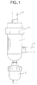
- Fig. 1 is a front view of a gas-liquid separator of a first embodiment
- Fig. 2 is a partly vertically sectional view of the gas-liquid separator shown in Fig. 1
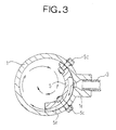
- Fig. 3 is a sectional view taken along the line A - A in Fig. 2
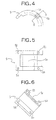
- Fig. 4 is a plan view of a blow guide plate in the gas-liquid separator shown in Fig. 2
- Fig. 5 is a side view of the blow guide plate
- Fig. 6 is a sectional view taken along the line B - B in Fig. 4
- Fig. 7 is a performance graph plotting a moisture removal rate of the gas-liquid separator shown in Fig. 1
- Fig. 8 is an explanatory view of the gas-liquid separator shown in Fig. 1, which illustrates how introduced air is separated into a flow of air and water drops.
- the reference numeral 1 is a cylindrical container having an inner diameter of 70 mm
- 1a is a high-pressure air introducing port having a diameter of 6 mm
- 1b is an air discharging port having a diameter of 4 mm
- 1c is a cover portion provided at the top of the cylindrical container
- 2 is an auto-drain connected to the bottom of the cylindrical container
- 3 is a high-pressure air supply pipe connected to the high-pressure air introducing port 1a
- 4 is a high-pressure air discharging pipe connected to the air discharging port 1b.
- the reference numeral 5 is a blow guide plate forming a blow guide part
- 5a is an air passing groove defined between an outer wall circumferential surface of the blow guide plate 5 and an inner wall surface of the cylindrical container 1.
- the air passing groove 5a has a curved shape following an inner wall surface of the cylindrical container 1. Air is released from a downstream end of the air passing groove 5a into the cylindrical container 1 near its inner wall surface so that the released air whirls along the inner wall surface of the cylindrical container 1 without colliding with the inner wall surface.
- the reference numeral 5b is an attachment hole for the blow guide plate 5
- 5c is an attachment bolt which is inserted into the attachment hole 5b
- 6 is a conical receiving plate provided in an upper portion within the cylindrical container 1
- 6a is a central opening formed at the center of the conical receiving plate 6 and having a diameter of 12 mm.
- the reference numeral 7 is a dome as a curved member welded to an upper central surface of the conical receiving plate 6, 7a are two ventholes formed in the dome 7, each having a diameter of 3 mm, 8 is a partition, 8a are two ventholes formed in the partition 8, each having a diameter of 3 mm, 9 is a first small chamber, 10 is a second small chamber, and 11 is a third small chamber.
- the distance between the high-pressure air introducing port 1a (the inner wall surface of the cylindrical container 1) and the groove surface of the air passing groove 5a, with which the blown air collides, is 5 mm.
- the air is thus steeply curved, and moisture in the air is partly separated by collision.
- the air is blown into the cylindrical container 1 from the downstream end of the air passing groove 5a, and then rises in the form of a spiral flow while whirling.
- the air passing groove 5a defined between the outer circumferential surface of the blow guide plate 5 and the inner wall surface of the cylindrical container 1 is curved so as to follow the inner wall surface of the cylindrical container, the introduced air is efficiently separated into gas and a liquid by collision, and also energy loss caused upon change in the air direction is reduced. After rising until striking against the conical receiving plate 6, the spiral flow descends along a lower surface of the conical receiving plate 6 toward the center thereof.
- Fig. 8 illustrates the above-described process in the cylindrical container 1.
- Water drops being forced outward by centrifugal force caused by the whirling of the spiral flow, are put on the inner wall surface of the cylindrical container 1, and then run downward along the inner wall surface. Some water drops are separated from the air before contacting with the inner wall surface due to a difference in specific gravity and fall down to a bottom surface of the cylindrical container 1.
- Moisture contained in the air flow striking against the conical receiving plate 6 is carried downward together with the air, separated from the air to form water drops due to a difference in specific gravity, and falls down to the bottom surface of the cylindrical container 1. The fallen water drops are then recovered into the auto-drain 2.
- the air in a central portion of the cylindrical container 1 gradually rises in a manner like being sucked from the above, and flows into the first small chamber 9 through the central opening 6a.
- the air flowing into the first small chamber 9 through the central opening 6a of the conical receiving plate 6 enters the second small chamber 10 through the ventholes 7a and then the third small chamber 11 through the ventholes 8a.
- the air is finally discharged to the air discharging pipe 4 through the air discharging port 1b in the third small chamber 11 after passing those small chambers.
- a dehumidifying capability of this embodiment 100 cc of water mixed with color ink was mixed into flows of high-pressure air having different flow rates from 100 to 500 liter per minute at a rate of 30 cc/min, as shown in Fig. 7.
- the resulting high-pressure air was blown into the high-pressure air of 10 atmospheres through the high-pressure air supply pipe 3.
- a graph of Fig. 7 plots the amount of the inked water recovered through the auto-drain 2 under the above condition in relation to the air flow rate.
- FIG. 9 is a front view of the gas-liquid separator of the second embodiment
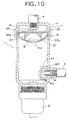
- Fig. 10 is a vertical sectional view of the gas-liquid separator shown in Fig. 9
- Fig. 11 is an exploded perspective view of an upper portion of the gas-liquid separator shown in Fig. 9
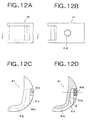
- Fig. 12A is a front view of a member forming an collision surface and a guide part
- Fig. 12B is a side view of the member
- Fig. 12C is a plan view of the member
- Fig. 9 is a front view of the gas-liquid separator of the second embodiment
- Fig. 10 is a vertical sectional view of the gas-liquid separator shown in Fig. 9
- Fig. 11 is an exploded perspective view of an upper portion of the gas-liquid separator shown in Fig. 9
- Fig. 12A is a front view of a member forming an collision surface and a guide part
- Fig. 12B is a side view of the member
- FIG. 12D is a sectional view taken along the line C - C in Fig. 12A;
- Fig. 13 is an exploded perspective view of the member forming the collision surface and the guide part, showing an assembled state;
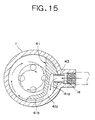
- Fig. 14 is an explanatory view of the gas-liquid separator shown in Fig. 9, which illustrates flows of air and moisture; and
- Fig. 15 is a sectional view taken along the line D - D in Fig. 14.
- This second embodiment differs from the first embodiment primarily in the structural members which correspond to the blow guide plate 5, the conical receiving plate 6, the dome 7 and the partition 8.
- the receiving plate 31 is formed to have a lower surface which has an arc-shaped sectional view, i.e., which constitutes part of a spherical surface.
- a partition 35 having a circular form in a plan view and a curved member 37 suspended from the partition 35 are formed integrally with each other. Further, the partition 35 and the curved member 37 have ventholes 35a, 37a are formed therein, respectively, so as to locate in 180 ° -opposite positions around the center of the curved member 37.
- the partition 35 and the curved member 37 are formed integrally with each other, the positional relationship between the ventholes 35a and 37a is maintained.
- the venthole 35a formed in the partition 35 and the venthole 37a formed in the curved member 37 are arranged in 180° - opposite positions around the center of the curved member 37, the venthole 37a of the curved member 37 and the venthole 35a of the partition 35 can be apart from each other to the maximum, causing the air discharged through the venthole 37a of the curved member 37 to temporarily remain in a space defined by an outer surface of the curved member 37, a lower surface of the partition 35 and the inner wall surface of the cylindrical container 1.
- water drops can be effectively prevented from blowing out together with the air after the gas-liquid separation.
- the blow guide member 41 which corresponds to the blow guide plate 5 in the first embodiment will be described.
- the blow guide member 41 comprises a linear collision surface 41a and a guide part 41b continuously extending from the collision surface 41a.
- the collision surface 41a is formed to extend linearly and inclined 3° in a direction to widen the air flow passage from a plane perpendicular to the incoming direction of air (see " ⁇ " in Fig. 12D).
- Such an inclination of the collision surface contributes to not only increasing the efficiency of liquefaction of moisture by collision with the surface, i.e., separation into gas and liquid, but also reducing energy loss caused upon subsequent change in the flow direction of the incoming air.
- the reference numeral 41d is an internal thread formed in the blow guide member 41, and 43 is an external thread which are able to mesh with the internal thread 41d.
- the external thread 43 has such an outer configuration as allowing its insertion into the high-pressure air introducing port 1a.
- the external thread 43 is provided with a flange portion 43b formed at a head end thereof to serve as a bearing surface, and cut slots 43a formed in the flange portion 43b in a radial direction for fastening the screw.
- the blow guide member 41 is placed in the cylindrical container 1 in a manner that the internal thread 41d is positioned to face the high-pressure air introducing port 1a, and the external thread 43 is inserted through the high-pressure air introducing port 1a, and meshed and fastened with the internal thread 41d of the blow guide member 41, thereby fixing the blow guide member 41. Accordingly, in this embodiment, the blow guide member 41 can be attached from the side of the high-pressure air introducing port 1a. This structure effectively prevents air from leaking through gaps around the attachment bolts 5c inserted through the attachment holes 5b, and hence air-tightness of the cylindrical container 1 can be maintained.
- gas-liquid separator of the second embodiment of the present invention can provide the above-mentioned advantages in addition to the various functions of the first embodiment described above.
- the present invention can be suitably employed to dehumidify air which is supplied to, for example, air-operated machines such as air motors and air breakers, air blowing apparatus for blowing away powdery dust, and air blowing apparatus for drying and cooling.
- air-operated machines such as air motors and air breakers, air blowing apparatus for blowing away powdery dust, and air blowing apparatus for drying and cooling.
Landscapes
- Chemical & Material Sciences (AREA)
- Chemical Kinetics & Catalysis (AREA)
- Separating Particles In Gases By Inertia (AREA)
- Cyclones (AREA)
- Gas Separation By Absorption (AREA)
- Degasification And Air Bubble Elimination (AREA)
- Drying Of Gases (AREA)
Applications Claiming Priority (3)
| Application Number | Priority Date | Filing Date | Title |
|---|---|---|---|
| JP19790597A JP3268298B2 (ja) | 1997-07-07 | 1997-07-07 | 高圧空気の除湿装置 |
| JP19790597 | 1997-07-07 | ||
| PCT/JP1998/002709 WO1999002240A1 (en) | 1997-07-07 | 1998-06-17 | Gas-liquid separator |
Publications (3)
| Publication Number | Publication Date |
|---|---|
| EP0923974A1 EP0923974A1 (en) | 1999-06-23 |
| EP0923974A4 EP0923974A4 (en) | 2000-01-05 |
| EP0923974B1 true EP0923974B1 (en) | 2005-05-04 |
Family
ID=16382237
Family Applications (1)
| Application Number | Title | Priority Date | Filing Date |
|---|---|---|---|
| EP98928559A Expired - Lifetime EP0923974B1 (en) | 1997-07-07 | 1998-06-17 | Gas-liquid separator |
Country Status (15)
| Country | Link |
|---|---|
| US (1) | US6156106A (id) |
| EP (1) | EP0923974B1 (id) |
| JP (1) | JP3268298B2 (id) |
| KR (1) | KR100343188B1 (id) |
| CN (1) | CN1130242C (id) |
| AT (1) | ATE294630T1 (id) |
| BR (1) | BR9806018A (id) |
| CA (1) | CA2264156C (id) |
| DE (1) | DE69830040T2 (id) |
| ID (1) | ID27362A (id) |
| IL (1) | IL128711A (id) |
| IS (1) | IS2166B (id) |
| MY (1) | MY120329A (id) |
| TW (1) | TW386893B (id) |
| WO (1) | WO1999002240A1 (id) |
Families Citing this family (44)
| Publication number | Priority date | Publication date | Assignee | Title |
|---|---|---|---|---|
| JP4906175B2 (ja) * | 2000-03-24 | 2012-03-28 | 株式会社カマタテクナス | 気液分離装置 |
| US7186095B2 (en) * | 2002-09-23 | 2007-03-06 | Tecumseh Products Company | Compressor mounting bracket and method of making |
| US6896496B2 (en) * | 2002-09-23 | 2005-05-24 | Tecumseh Products Company | Compressor assembly having crankcase |
| US6887050B2 (en) * | 2002-09-23 | 2005-05-03 | Tecumseh Products Company | Compressor having bearing support |
| US7063523B2 (en) | 2002-09-23 | 2006-06-20 | Tecumseh Products Company | Compressor discharge assembly |
| US7163383B2 (en) | 2002-09-23 | 2007-01-16 | Tecumseh Products Company | Compressor having alignment bushings and assembly method |
| US7018183B2 (en) * | 2002-09-23 | 2006-03-28 | Tecumseh Products Company | Compressor having discharge valve |
| US7018184B2 (en) * | 2002-09-23 | 2006-03-28 | Tecumseh Products Company | Compressor assembly having baffle |
| US7094043B2 (en) * | 2002-09-23 | 2006-08-22 | Tecumseh Products Company | Compressor having counterweight shield |
| US7060002B1 (en) * | 2002-10-21 | 2006-06-13 | Boehme Theodore F | Physical fitness course |
| RU2275228C1 (ru) * | 2004-10-14 | 2006-04-27 | Федеральное государственное унитарное предприятие Центральное конструкторское бюро машиностроения (ФГУП "ЦКБМ") | Сепаратор |
| NO329480B1 (no) * | 2005-03-16 | 2010-10-25 | Norsk Hydro As | Anordning ved en rorseparator |
| CN100531849C (zh) * | 2006-07-05 | 2009-08-26 | 富准精密工业(深圳)有限公司 | 气液分离装置及方法 |
| KR100901741B1 (ko) * | 2008-10-24 | 2009-06-10 | 김성우 | 볼텍스 튜브를 이용한 공기 건조기 |
| JP5439026B2 (ja) * | 2009-05-11 | 2014-03-12 | 株式会社神戸製鋼所 | 気液分離器 |
| CN101949380B (zh) * | 2010-10-11 | 2011-12-07 | 吉首大学 | 一种压缩机分离器除沫装置 |
| JP5520800B2 (ja) * | 2010-12-17 | 2014-06-11 | 株式会社神戸製鋼所 | 油分離器 |
| JP5767322B2 (ja) * | 2011-05-19 | 2015-08-19 | 株式会社コガネイ | フィルタ |
| KR101218403B1 (ko) * | 2012-07-16 | 2013-01-03 | 강릉원주대학교산학협력단 | 배출 가스 정화 장치 및 이의 배플 |
| DE112013003821T5 (de) * | 2012-07-31 | 2015-05-21 | Cummins Filtration Ip, Inc. | Verfahren und Vorrichtungen zum Abscheiden einer Flüssigkeit aus einem Gas-Flüssigkeit-Strom |
| KR20160038738A (ko) * | 2014-09-30 | 2016-04-07 | 주식회사 엘지화학 | 분리기 |
| SE538760C2 (sv) * | 2015-03-12 | 2016-11-15 | Valmet Oy | Cyclone separator arrangement and method |
| CN105169814B (zh) * | 2015-10-15 | 2017-11-07 | 中国商用飞机有限责任公司 | 气液分离装置 |
| CN105498432A (zh) * | 2016-02-02 | 2016-04-20 | 徐彬 | 含尘气体的除尘方法及装置 |
| CN107096354A (zh) * | 2017-05-05 | 2017-08-29 | 温州中环正源水务有限公司 | 污泥干化载气系统 |
| US10966583B2 (en) * | 2019-01-23 | 2021-04-06 | Omachron Intellectual Property Inc. | Surface cleaning apparatus, cyclonic air treatment member and surface cleaning apparatus including the same |
| US11219906B2 (en) | 2019-01-23 | 2022-01-11 | Omachron Intellectual Property Inc. | Surface cleaning apparatus, cyclonic air treatment member and surface cleaning apparatus including the same |
| CN108704392B (zh) * | 2018-05-29 | 2020-07-17 | 中国人民解放军国防科技大学 | 离心力惯性级联式气液分离器 |
| US11059054B2 (en) * | 2019-01-23 | 2021-07-13 | Omachron Intellectual Property Inc. | Surface cleaning apparatus, cyclonic air treatment member and surface cleaning apparatus including the same |
| US10925451B2 (en) * | 2019-01-23 | 2021-02-23 | Omachron Intellectual Property Inc. | Surface cleaning apparatus, cyclonic air treatment member and surface cleaning apparatus including the same |
| US11135602B2 (en) * | 2019-01-23 | 2021-10-05 | Omachron Intellectual Property Inc. | Surface cleaning apparatus, cyclonic air treatment member and surface cleaning apparatus including the same |
| US10974258B2 (en) * | 2019-01-23 | 2021-04-13 | Omachron Intellectual Property Inc. | Surface cleaning apparatus, cyclonic air treatment member and surface cleaning apparatus including the same |
| US11213832B2 (en) * | 2019-01-23 | 2022-01-04 | Omachron Intellectual Property Inc. | Surface cleaning apparatus, cyclonic air treatment member and surface cleaning apparatus including the same |
| US10919051B2 (en) * | 2019-01-23 | 2021-02-16 | Omachron Intellectual Property Inc. | Surface cleaning apparatus, cyclonic air treatment member and surface cleaning apparatus including the same |
| US11129510B2 (en) * | 2019-01-23 | 2021-09-28 | Omachron Intellectual Property Inc. | Surface cleaning apparatus, cyclonic air treatment member and surface cleaning apparatus including the same |
| WO2020186342A1 (en) | 2019-03-15 | 2020-09-24 | Omachron Intellectual Property Inc. | Surface cleaning apparatus |
| JP6826144B2 (ja) * | 2019-03-19 | 2021-02-03 | 日本エアードライヤー販売株式会社 | 圧縮空気の凝縮方法および圧縮空気の凝縮装置 |
| CN110090517B (zh) * | 2019-05-08 | 2023-09-08 | 俞春华 | 一种阶梯式气液分离器 |
| CN113134284B (zh) * | 2020-01-19 | 2022-08-30 | 中国石油天然气股份有限公司 | 气体脱硫排放装置 |
| CN112473247A (zh) * | 2020-11-16 | 2021-03-12 | 亚普汽车部件股份有限公司 | 一种油气分离装置 |
| JP7521684B2 (ja) * | 2021-03-04 | 2024-07-24 | 株式会社島津製作所 | ガス分析装置 |
| CN115638307B (zh) * | 2022-09-30 | 2026-03-03 | 合肥江航飞机装备股份有限公司 | 一种气体管路自动排液装置及方法 |
| KR102747689B1 (ko) * | 2024-01-25 | 2024-12-27 | (주)씨에스아이테크 | 수분유입을 방지하기 위한 공기 흡입장치 |
| CN117883881B (zh) * | 2024-03-14 | 2024-06-04 | 福建伊普思实业有限公司 | 一种气液分离器及其使用方法 |
Family Cites Families (10)
| Publication number | Priority date | Publication date | Assignee | Title |
|---|---|---|---|---|
| US1779023A (en) * | 1928-12-26 | 1930-10-21 | Smith Separator Company | Oil and gas separator |
| US2037426A (en) * | 1935-08-09 | 1936-04-14 | Smith Separator Corp | Oil and gas separator |
| US3246454A (en) * | 1962-03-01 | 1966-04-19 | Products Company Van | Gas drier |
| GB2036606A (en) * | 1978-11-24 | 1980-07-02 | Plenty Group Ltd | Vortex separators |
| US4187088A (en) * | 1979-01-18 | 1980-02-05 | Maloney-Crawford Corporation | Down flow centrifugal separator |
| GB2125352B (en) * | 1982-08-18 | 1986-02-19 | Walker Wingsail Syst | Pressure sensing on rigid sails |
| JPS6021553U (ja) * | 1983-07-22 | 1985-02-14 | 日産自動車株式会社 | 改質ガスの凝縮液分離器 |
| JPH0398918U (id) * | 1990-01-29 | 1991-10-15 | ||
| US5599365A (en) | 1995-03-03 | 1997-02-04 | Ingersoll-Rand Company | Mechanical fluid separator |
| JP2805138B2 (ja) * | 1995-04-20 | 1998-09-30 | 勉 鎌田 | 圧縮空気の除湿装置 |
-
1997
- 1997-07-07 JP JP19790597A patent/JP3268298B2/ja not_active Expired - Fee Related
-
1998
- 1998-06-17 US US09/242,201 patent/US6156106A/en not_active Expired - Lifetime
- 1998-06-17 DE DE69830040T patent/DE69830040T2/de not_active Expired - Lifetime
- 1998-06-17 ID IDW990043D patent/ID27362A/id unknown
- 1998-06-17 KR KR1019997001617A patent/KR100343188B1/ko not_active Expired - Lifetime
- 1998-06-17 CA CA002264156A patent/CA2264156C/en not_active Expired - Fee Related
- 1998-06-17 EP EP98928559A patent/EP0923974B1/en not_active Expired - Lifetime
- 1998-06-17 BR BR9806018-0A patent/BR9806018A/pt not_active IP Right Cessation
- 1998-06-17 AT AT98928559T patent/ATE294630T1/de not_active IP Right Cessation
- 1998-06-17 CN CN98800945A patent/CN1130242C/zh not_active Expired - Lifetime
- 1998-06-17 TW TW087109703A patent/TW386893B/zh not_active IP Right Cessation
- 1998-06-17 IL IL12871198A patent/IL128711A/en not_active IP Right Cessation
- 1998-06-17 WO PCT/JP1998/002709 patent/WO1999002240A1/ja not_active Ceased
- 1998-06-27 MY MYPI98002941A patent/MY120329A/en unknown
-
1999
- 1999-02-26 IS IS4986A patent/IS2166B/is unknown
Also Published As
| Publication number | Publication date |
|---|---|
| CN1130242C (zh) | 2003-12-10 |
| IS2166B (is) | 2006-11-15 |
| CN1230898A (zh) | 1999-10-06 |
| ID27362A (id) | 2001-04-05 |
| JPH1119462A (ja) | 1999-01-26 |
| IL128711A0 (en) | 2000-01-31 |
| CA2264156A1 (en) | 1999-01-21 |
| MY120329A (en) | 2005-10-31 |
| JP3268298B2 (ja) | 2002-03-25 |
| EP0923974A4 (en) | 2000-01-05 |
| WO1999002240A1 (en) | 1999-01-21 |
| ATE294630T1 (de) | 2005-05-15 |
| TW386893B (en) | 2000-04-11 |
| IS4986A (is) | 1999-02-26 |
| IL128711A (en) | 2001-12-23 |
| HK1023081A1 (en) | 2000-09-01 |
| DE69830040D1 (de) | 2005-06-09 |
| BR9806018A (pt) | 2000-01-18 |
| US6156106A (en) | 2000-12-05 |
| EP0923974A1 (en) | 1999-06-23 |
| KR100343188B1 (ko) | 2002-07-10 |
| DE69830040T2 (de) | 2005-09-29 |
| KR20000034843A (ko) | 2000-06-26 |
| CA2264156C (en) | 2004-08-31 |
Similar Documents
| Publication | Publication Date | Title |
|---|---|---|
| EP0923974B1 (en) | Gas-liquid separator | |
| CN101222964B (zh) | 用于分离混合物的系统及入口装置 | |
| JP2830618B2 (ja) | 遠心分離形油分離器 | |
| US5746791A (en) | Moisture and contaminant separator for compressed air | |
| US9174225B2 (en) | Filter | |
| JP4125822B2 (ja) | 気液分離装置 | |
| WO2013094161A1 (ja) | 気液分離装置 | |
| KR100449398B1 (ko) | 기액분리장치 | |
| CN101322908A (zh) | 湿式高效脱硫除尘装置及方法 | |
| JP2805138B2 (ja) | 圧縮空気の除湿装置 | |
| US4848988A (en) | Compressed air dehumidifier | |
| FI109455B (fi) | Kompakti kaskadipesuri poistokaasun pesemiseksi | |
| US3969093A (en) | Cyclonic gas scrubbing system | |
| MXPA99002166A (en) | Gas-liquid separator | |
| US5228890A (en) | Cyclone separator | |
| JPH06346855A (ja) | 圧縮空気の除湿装置 | |
| US4164398A (en) | Entrainment separator | |
| US3751882A (en) | Gas scrubber with moisture eliminator | |
| CA2358580C (en) | Droplet separator | |
| JP3728516B2 (ja) | 液分離器 | |
| KR100780839B1 (ko) | 컴프레서용 필터 | |
| RU2174040C1 (ru) | Мокрый пылеуловитель | |
| SU1726053A1 (ru) | Каплеуловитель | |
| JPH047499Y2 (id) | ||
| SU1766526A1 (ru) | Циклонный сепаратор |
Legal Events
| Date | Code | Title | Description |
|---|---|---|---|
| PUAI | Public reference made under article 153(3) epc to a published international application that has entered the european phase |
Free format text: ORIGINAL CODE: 0009012 |
|
| 17P | Request for examination filed |
Effective date: 19990218 |
|
| AK | Designated contracting states |
Kind code of ref document: A1 Designated state(s): AT BE CH DE DK ES FI FR GB GR IE IT LI LU NL PT SE |
|
| A4 | Supplementary search report drawn up and despatched |
Effective date: 19991119 |
|
| AK | Designated contracting states |
Kind code of ref document: A4 Designated state(s): AT BE CH DE DK ES FI FR GB GR IE IT LI LU NL PT SE |
|
| 17Q | First examination report despatched |
Effective date: 20031016 |
|
| GRAP | Despatch of communication of intention to grant a patent |
Free format text: ORIGINAL CODE: EPIDOSNIGR1 |
|
| GRAS | Grant fee paid |
Free format text: ORIGINAL CODE: EPIDOSNIGR3 |
|
| GRAA | (expected) grant |
Free format text: ORIGINAL CODE: 0009210 |
|
| AK | Designated contracting states |
Kind code of ref document: B1 Designated state(s): AT BE CH DE DK ES FI FR GB GR IE IT LI LU NL PT SE |
|
| PG25 | Lapsed in a contracting state [announced via postgrant information from national office to epo] |
Ref country code: NL Free format text: LAPSE BECAUSE OF FAILURE TO SUBMIT A TRANSLATION OF THE DESCRIPTION OR TO PAY THE FEE WITHIN THE PRESCRIBED TIME-LIMIT Effective date: 20050504 Ref country code: LI Free format text: LAPSE BECAUSE OF FAILURE TO SUBMIT A TRANSLATION OF THE DESCRIPTION OR TO PAY THE FEE WITHIN THE PRESCRIBED TIME-LIMIT Effective date: 20050504 Ref country code: FI Free format text: LAPSE BECAUSE OF FAILURE TO SUBMIT A TRANSLATION OF THE DESCRIPTION OR TO PAY THE FEE WITHIN THE PRESCRIBED TIME-LIMIT Effective date: 20050504 Ref country code: ES Free format text: LAPSE BECAUSE OF FAILURE TO SUBMIT A TRANSLATION OF THE DESCRIPTION OR TO PAY THE FEE WITHIN THE PRESCRIBED TIME-LIMIT Effective date: 20050504 Ref country code: CH Free format text: LAPSE BECAUSE OF FAILURE TO SUBMIT A TRANSLATION OF THE DESCRIPTION OR TO PAY THE FEE WITHIN THE PRESCRIBED TIME-LIMIT Effective date: 20050504 Ref country code: BE Free format text: LAPSE BECAUSE OF FAILURE TO SUBMIT A TRANSLATION OF THE DESCRIPTION OR TO PAY THE FEE WITHIN THE PRESCRIBED TIME-LIMIT Effective date: 20050504 Ref country code: AT Free format text: LAPSE BECAUSE OF FAILURE TO SUBMIT A TRANSLATION OF THE DESCRIPTION OR TO PAY THE FEE WITHIN THE PRESCRIBED TIME-LIMIT Effective date: 20050504 |
|
| REG | Reference to a national code |
Ref country code: GB Ref legal event code: FG4D |
|
| REG | Reference to a national code |
Ref country code: CH Ref legal event code: EP |
|
| REG | Reference to a national code |
Ref country code: IE Ref legal event code: FG4D |
|
| REF | Corresponds to: |
Ref document number: 69830040 Country of ref document: DE Date of ref document: 20050609 Kind code of ref document: P |
|
| PG25 | Lapsed in a contracting state [announced via postgrant information from national office to epo] |
Ref country code: LU Free format text: LAPSE BECAUSE OF NON-PAYMENT OF DUE FEES Effective date: 20050617 Ref country code: IE Free format text: LAPSE BECAUSE OF NON-PAYMENT OF DUE FEES Effective date: 20050617 |
|
| PG25 | Lapsed in a contracting state [announced via postgrant information from national office to epo] |
Ref country code: SE Free format text: LAPSE BECAUSE OF FAILURE TO SUBMIT A TRANSLATION OF THE DESCRIPTION OR TO PAY THE FEE WITHIN THE PRESCRIBED TIME-LIMIT Effective date: 20050804 Ref country code: GR Free format text: LAPSE BECAUSE OF FAILURE TO SUBMIT A TRANSLATION OF THE DESCRIPTION OR TO PAY THE FEE WITHIN THE PRESCRIBED TIME-LIMIT Effective date: 20050804 Ref country code: DK Free format text: LAPSE BECAUSE OF FAILURE TO SUBMIT A TRANSLATION OF THE DESCRIPTION OR TO PAY THE FEE WITHIN THE PRESCRIBED TIME-LIMIT Effective date: 20050804 |
|
| PG25 | Lapsed in a contracting state [announced via postgrant information from national office to epo] |
Ref country code: PT Free format text: LAPSE BECAUSE OF FAILURE TO SUBMIT A TRANSLATION OF THE DESCRIPTION OR TO PAY THE FEE WITHIN THE PRESCRIBED TIME-LIMIT Effective date: 20051017 |
|
| NLV1 | Nl: lapsed or annulled due to failure to fulfill the requirements of art. 29p and 29m of the patents act | ||
| REG | Reference to a national code |
Ref country code: CH Ref legal event code: PL |
|
| PLBE | No opposition filed within time limit |
Free format text: ORIGINAL CODE: 0009261 |
|
| STAA | Information on the status of an ep patent application or granted ep patent |
Free format text: STATUS: NO OPPOSITION FILED WITHIN TIME LIMIT |
|
| REG | Reference to a national code |
Ref country code: IE Ref legal event code: MM4A |
|
| ET | Fr: translation filed | ||
| 26N | No opposition filed |
Effective date: 20060207 |
|
| REG | Reference to a national code |
Ref country code: FR Ref legal event code: PLFP Year of fee payment: 19 |
|
| REG | Reference to a national code |
Ref country code: FR Ref legal event code: PLFP Year of fee payment: 20 |
|
| PGFP | Annual fee paid to national office [announced via postgrant information from national office to epo] |
Ref country code: GB Payment date: 20170629 Year of fee payment: 20 Ref country code: FR Payment date: 20170629 Year of fee payment: 20 |
|
| PGFP | Annual fee paid to national office [announced via postgrant information from national office to epo] |
Ref country code: DE Payment date: 20170830 Year of fee payment: 20 Ref country code: IT Payment date: 20170721 Year of fee payment: 20 |
|
| REG | Reference to a national code |
Ref country code: DE Ref legal event code: R071 Ref document number: 69830040 Country of ref document: DE |
|
| REG | Reference to a national code |
Ref country code: GB Ref legal event code: PE20 Expiry date: 20180616 |
|
| PG25 | Lapsed in a contracting state [announced via postgrant information from national office to epo] |
Ref country code: GB Free format text: LAPSE BECAUSE OF EXPIRATION OF PROTECTION Effective date: 20180616 |