EP0921938B1 - Machine et procede de fabrication d'une feuille de carton ondule simple face avec traction en amont - Google Patents
Machine et procede de fabrication d'une feuille de carton ondule simple face avec traction en amont Download PDFInfo
- Publication number
- EP0921938B1 EP0921938B1 EP97935614A EP97935614A EP0921938B1 EP 0921938 B1 EP0921938 B1 EP 0921938B1 EP 97935614 A EP97935614 A EP 97935614A EP 97935614 A EP97935614 A EP 97935614A EP 0921938 B1 EP0921938 B1 EP 0921938B1
- Authority
- EP
- European Patent Office
- Prior art keywords
- sheet
- rollers
- roller
- fluted
- speed
- Prior art date
- Legal status (The legal status is an assumption and is not a legal conclusion. Google has not performed a legal analysis and makes no representation as to the accuracy of the status listed.)
- Expired - Lifetime
Links
Images


Classifications
-
- B—PERFORMING OPERATIONS; TRANSPORTING
- B31—MAKING ARTICLES OF PAPER, CARDBOARD OR MATERIAL WORKED IN A MANNER ANALOGOUS TO PAPER; WORKING PAPER, CARDBOARD OR MATERIAL WORKED IN A MANNER ANALOGOUS TO PAPER
- B31F—MECHANICAL WORKING OR DEFORMATION OF PAPER, CARDBOARD OR MATERIAL WORKED IN A MANNER ANALOGOUS TO PAPER
- B31F1/00—Mechanical deformation without removing material, e.g. in combination with laminating
- B31F1/20—Corrugating; Corrugating combined with laminating to other layers
- B31F1/24—Making webs in which the channel of each corrugation is transverse to the web feed
- B31F1/26—Making webs in which the channel of each corrugation is transverse to the web feed by interengaging toothed cylinders cylinder constructions
- B31F1/28—Making webs in which the channel of each corrugation is transverse to the web feed by interengaging toothed cylinders cylinder constructions combined with uniting the corrugated webs to flat webs ; Making double-faced corrugated cardboard
- B31F1/2831—Control
-
- B—PERFORMING OPERATIONS; TRANSPORTING
- B31—MAKING ARTICLES OF PAPER, CARDBOARD OR MATERIAL WORKED IN A MANNER ANALOGOUS TO PAPER; WORKING PAPER, CARDBOARD OR MATERIAL WORKED IN A MANNER ANALOGOUS TO PAPER
- B31F—MECHANICAL WORKING OR DEFORMATION OF PAPER, CARDBOARD OR MATERIAL WORKED IN A MANNER ANALOGOUS TO PAPER
- B31F1/00—Mechanical deformation without removing material, e.g. in combination with laminating
- B31F1/20—Corrugating; Corrugating combined with laminating to other layers
- B31F1/24—Making webs in which the channel of each corrugation is transverse to the web feed
- B31F1/26—Making webs in which the channel of each corrugation is transverse to the web feed by interengaging toothed cylinders cylinder constructions
- B31F1/28—Making webs in which the channel of each corrugation is transverse to the web feed by interengaging toothed cylinders cylinder constructions combined with uniting the corrugated webs to flat webs ; Making double-faced corrugated cardboard
- B31F1/2845—Details, e.g. provisions for drying, moistening, pressing
Definitions
- the present invention relates to the manufacture of corrugated board and more particularly a machine for making a simple corrugated sheet side by gluing of a corrugated sheet of cardboard on a flat sheet of cardboard called sheet of cover, of the type comprising a set of three heating cylinders, namely a first cylinder fluted, preforming a flat sheet into fluted sheet, a second cylinder, fluted, central, and a third cylinder, smooth, supplying the flat sheet, called the cover sheet, in contact with the grooves of the fluted sheet at the periphery of the second cylinder, said machine comprising more of the first means of positive training by traction of the flat sheet intended to be fluted upstream of the cylinder set.
- It also relates to a method of manufacture of single-sided corrugated cardboard sheets using in particular a machine of the above type.
- FIG. 1 shows a machine 1 of the prior art in a production line 2 of single-sided corrugated cardboard.
- the chain includes supply means 3 and 4 respectively in flat sheet, of cover, and in flat sheet intended to form the sheet grooved.
- These supply means include, so known in itself, from the reels 5 which allow good control of the progress and braking necessary for the production of cardboard.
- preheater 6 for the cover sheet, generally consisting a steam-heated steel cylinder with small rollers called “bar feeders" which are used to make vary the paper / cylinder contact area, and a preconditioner 7 for the fluted sheet, which meanwhile, and in addition, a ramp humidification of the leaf which promotes formation of grooves.
- the chain 2 also includes means evacuation 8 of the single-sided cardboard obtained, constituted by a system of belts partly high of the chain.
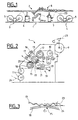
- Figure 2 shows more specifically, in view cutting, the machine 1 single face of the chain of figure 1.
- the machine 1 also includes a first cylinder 12, grooved, upper, stainless steel. It is hollow and designed to be heated by steam in a manner known in itself.
- Machine 1 also includes a second cylinder 13, grooved, central, stainless steel, axis parallel to that of the first cylinder substantially tangent to the latter, and for example from same diameter.
- the second cylinder is for example of the type known as "Air Drive”, manufactured by the French company MARTIN.
- the chamber includes 17 channels drilled over the entire length of the cylinder and communicating with the surface peripheral fluted by holes.
- Machine 1 includes a third cylinder 18 lower, smooth surface, axis parallel to both first and for example of the same diameter.
- This cylinder is steam heated in a similar fashion to both first and is arranged to compress the cover sheet against edges of grooves of the grooved sheet, in contact with the periphery of the central grooved cylinder, as we go to see him.
- the machine 1 also comprises means 19 gluing the ridges of the grooves, known in themselves, comprising a laminating roller 20, a glue 21 and a glue roller 22.
- the operating principle of the machine 1 is the next.
- the sheet 23 is intended to form the sheet grooved.
- the vacuum created in the lower part of the cylinder 13 then plates the fluted sheet 23 formed against the heating cylinder on an arc of circle with an apex angle equal to around 180 °.
- the glue is for example based on starch.
- the cover sheet 24 is introduced in the lower part and opposite the machine 1.
- the adhesive joint is therefore obtained by the action combined with high pressure and temperature in a fraction of a second.
- the fluted sheet is driven by the meshing of the grooved cylinders 12 and 13, and the cover sheet is driven by clamping between the central cylinder 13 and the smooth cylinder 18, no further traction upstream or downstream of the three cylinders not being produced.
- Corrugated cardboard is then evacuated in the upper part in a manner known in herself by treadmill.
- the result is corrugated cardboard, the moisture resistance characteristics, bursting of the cover, and resistance to compression on the field is reduced.
- Document US 2,742,079 thus provides for supply means with positive traction located upstream and away from the fluted rollers of which they are separated by a mechanical regulating adapter the spacing of the grooved rollers.
- Document GB 1.052.659 provides for means adapters located directly upstream of the rollers grooved, so as to supply them without tension.
- the present invention aims to provide a machine and a simple corrugated cardboard manufacturing process face responding better than those previously known to the requirements of the practice, in particular in that it improves the quality of the corrugated cardboard obtained minimizing the risk of paper cuts to resonant and / or high speed speeds i.e. for example greater than 300 m / min, for a low cost and easy to implement.
- the present invention leaves especially the idea of always keeping in tension constant the paper between the traction means positive and fluted rollers, using elastic stretching of the paper.
- the present invention provides in particular a machine for manufacturing a sheet of single-sided corrugated cardboard by gluing a sheet fluted cardboard on a flat sheet of cardboard, comprising a set of three heating cylinders, to know a first grooved cylinder, of preformation of a flat sheet of fluted sheet, a second cylinder, grooved, central, and a third cylinder, smooth, bringing the flat sheet, called cover, in contact with the grooves of the fluted sheet on the periphery of the second cylinder, said machine further comprising first means of positive traction training of the flat sheet intended to be grooved located directly in upstream and near the first cylinder characterized in that said first means positive training include motor means arranged to obtain, at the output of said first drive means positive, a constant speed of feeding of grooved cylinders in flat sheet always strictly lower than the linear speed of the sheet imposed at the entrance of said grooved cylinders by the speed of rotation of said cylinders fluted.
- the line speed of the cardboard is directly proportional to the speed of rotation corrugated cylinders corrected by the factor called consumption factor by those skilled in the art, depending on the type of groove (pitch, height, shape, etc.).
- Directly nearby means that the point belonging to the means of traction closest to the cylinder concerned (belonging to the set of three single-sided machine cylinders) is one distance between a few tenths of millimeters (sufficient not to be in contact) and of the order of 2 m, for example at a distance less than about 1 m, and advantageously less than or equal to about 50 cm, without a other element does not exist between the means and the cylinder closest to the game of cylinders.
- the under-speed of the fourth and / or the fifth cylinder or other types of training means is less at around 5%, 3% or even 1% or 0.5% compared to the speed of the cardboard, which may be the speed, respectively, of the first and / or the third cylinder in case of total absence of slip.
- the adjustment means are for example known spacer means between the periphery of the cylinder in themselves.
- the flat sheet is pressed on the fourth or fifth heating cylinder on the side where the glue is applied by the gluing means of grooves.
- the machine has automatic means of adjustment of the relative speeds of the fourth, fifth and / or sixth cylinders compared to the cardboard running speed, for example measured optically or via the rotation speed of a cylinder of the set of three cylinders.
- the invention also provides a method of making a single sheet of corrugated cardboard face, using a machine as described above.
- the invention is particularly applicable to the making a single sheet of corrugated cardboard face from a sheet of fluted cardboard with type B, C or E splines, and a flat sheet of cardboard, called a cover, by gluing one on the other, said sheets being made from grammage paper less than 140 g, advantageously less than 100 g and / or advantageously between around 80 g and around 130 g.
- Scroll speed of cardboard during said manufacturing is greater than 250 m / min, advantageously greater than 350 m / min, of preferably more than 400 m / min and even more preferably greater than 450 m / min, or even 500 m / min.
- the machine according to the embodiment of the invention more particularly described here comprises on the one hand, a single-sided machine of the type described in reference to FIG. 2, and on the other hand fourth, fifth and sixth cylinders that go be described with reference to Figures 4, 5 and 6.
- the machine in addition to the first, second and third cylinders 12, 13 and 18, the machine according to the mode of embodiment of the invention more particularly described here therefore comprises a fourth cylinder 26, a fifth cylinder 27 and a sixth cylinder 28.
- Each of these cylinders is smooth, heating, fitted with a suction application system which will be described later for a single cylinder.
- the cylinder 26 is steam heated so similar to other cylinders, for example for reach cylinder skin temperature between 160 ° C and 200 ° C.
- It consists of a hollow steel tube stainless and for example has a diameter identical to the others.
- the cylinder 26 is for example here again of the "Air Drive” type, manufactured by the French company MARTIN and known under the reference M 260. It includes two ends 29 and 30, mounted on bearings 31, and a cylindrical body 32, provided with a recess central cylindrical 33 supplied with steam at 34 by one of its ends 30. A drainage channel 35 condensate is also provided at this end.
- the other end 29 of the cylinder 26 has means 36 for rotating, by motor nominal operating speed fixed with respect to the speed of the first single machine roller face, for example strictly less than the latter, or with a tolerance of ⁇ 2%, of when the sheet feeding speed is flat is less than the speed of the cardboard at the output of the cylinder set.
- the surface 37 of the periphery of the body cylindrical 32 is smooth. By smooth surface, it should hear a flat cylindrical surface not grooved, but may have slight indentations or lunules 38, for example in the form of rectangular slots 40 mm long by 2.5 mm wide and the bottom of which is in the form of a portion of cylinder with large radius of curvature.
- indentations generally occupy less than 5% of the area of the cylinder, for example 2.8% and are connected to vacuum means 39 via two chambers in an arc 41 connected to channels longitudinal peripherals 42 angularly distributed and regularly connected to lunules 38 via small radial channels 43.
- the chambers 41 belong respectively to two fixed crowns 44 of distribution planned on either side of cylinder 26 with which they cooperate in rotation, friction, in a substantially sealed manner, by their side wall.
- a vacuum breaker 45 and / or take-off device carton 46 by injecting compressed air 47 into the channels 42, opposite point 40, is also advantageously provided in a manner known per se.
- the traction on the cardboard sheet is ensured thanks to the speed of the suction cylinder 26, on which is coated the cardboard cover sheet wavy without possibility or practically without possibility of sliding.
- the space between the grooved cylinder 13, central, and the third cylinder 18, smooth, at the point of contact or junction of the two sheets, is greater than the maximum thickness of a sheet of corrugated cardboard treat, so that the pressure is zero whatever the papers.
- a vacuum breaker and / or take-off device cardboard (not shown) known in itself, is also planned similarly to the point of peeling off the sheet of corrugated cardboard.
- V being the speed of movement of the cardboard
- V1 the external speed V1 of the cylinders 26 and 27 is for example equal to 0.95V nominal, or else 0.99 V.
- the speed of the cardboard is then controlled precisely in a manner known per se, for example by optical sensor.
- the speed V2 of the cylinder 28 is greater than that of cardboard, for example equal to 1.05V.
- the cylinders 26 and 27 have axes 26 ', 27' located accordingly with respect to the plane tangent to point of contact with the first or third adjacent cylinder.
- the axes of the cylinders 12 and 26 are therefore located on the same side of the plane tangent to these two cylinders and the axes of cylinders 18 and 27, on either side of the corresponding tangent plane.
- Small non-heating rollers 51 and 52 smooth and full, of a type known per se, are by example provided to allow windings according to the angles ⁇ and ⁇ , presenting lower generators 53, 54 located below planes tangent to the upper generator 55, 56 corresponding cylinders.
- the position is adjustable for allow modification of the winding angles.
- sufficient distances between the side walls of the cylinders are provided to allow the sheet to run smoothly cardboard.
- the sheet intended to be fluted by the first heating cylinder 12 is pulled by the fourth cylinder 26 with slightly lower speed to that of cardboard, which is measured nearby by encoder.
- the cylinder 26 therefore completely relieves the cylinder 12 of this work.
- the sheet is sucked by this fourth cylinder on an angle ⁇ between 90 ° and 180 °.
- the flat cover sheet is pulled by the roller 27, with a speed a little lower than that of the cardboard measured nearby by encoder, which at least partially relieves or even fully the means of traction which can also exist downstream as we will see with the cylinder 28.
- the traction is done here again and for example by suction the roller at an angle, for example 100 °, before travel a short distance, for example 50cm without no contact with a cylinder to reach the third cylinder surface 18.
- corrugated sheet formed by the fluted sheet previously glued and the sheet plane remains in contact with the heating cylinder 13 up to point 57, where the sheet takes off favored by a jet of compressed air.
- the corrugated sheet is then taken up by the sixth cylinder 28, smooth, heating and by suction example, the cover sheet being side of the surface of said cylinder, moreover operated at a speed slightly higher than that of the second cylinder. It then constitutes the means positive drive by pulling on said sheet of corrugated cardboard downstream, for example with a tensile force between 1 and 2 N / cm, for example greater than 1.5 N / cm.
- the sheet is sucked through the holes in the surface of cylinder 28, for example 180 °, front blast separation as described above, then deflection by the roller 52 and evacuation.
- the cylinder 28 is not aspiring, but simply smooth and heating on a circular arc ⁇ , which allows complete the heating of the glue. Dispositions complementary then remain identical to what is described above, if applicable.
- the tensile force exerted on the cardboard wavy by positive drive means consisting of the fourth and fifth cylinders is greater than about 4 N / cm, for example around 5 N / cm or around 8 N / cm.
- the fourth, fifth and sixth cylinders have their rotational speed automatically controlled by automatic means programmable 58 (in phantom in the figure) at the speed of movement of the cardboard, for example obtained by encoder, in a manner known per se.
- the present invention is not limited to the embodiment more particularly described. It also concerns and especially cases where the means of training positive pulling are ways to pinching between rollers of elastic material, belt drive means supported on a flat or cylindrical sheet, or on another belt, cases where there are means of heating complementary for example constituted by a table heated or by an electric dryer or a dryer infrared.
Landscapes
- Engineering & Computer Science (AREA)
- Mechanical Engineering (AREA)
- Machines For Manufacturing Corrugated Board In Mechanical Paper-Making Processes (AREA)
Description
- la vitesse des premiers moyens d'entraínement positif est inférieure ou égale à de l'ordre de 1 % par rapport à ladite vitesse linéaire;
- la vitesse des premiers moyens d'entraínement positif est inférieure ou égale à de l'ordre de 5 %, par exemple égale à de l'ordre de 3 %, par rapport à la vitesse linéaire;
- la machine comprend des deuxièmes moyens d'entraínement positif par traction de la feuille plane de couverture, directement en amont et à proximité du troisième cylindre;
- la tension entre les premiers et/ou deuxièmes moyens d'entraínement positif et le jeu de cylindres est supérieure à 2 kg/cm;
- la traction positive exercée par les premiers et/ou deuxièmes moyens d'entraínement positif sur la feuille plane est supérieure à de l'ordre de 3,5 N/cm;
- la traction positive exercée par les premiers et/ou deuxième moyens d'entraínement positif sur la feuille plane est supérieure à de l'ordre de 5 N/cm;
- la machine comporte de plus un cylindre supplémentaire lisse, chauffant, situé entièrement en aval du trajet du carton ondulé par rapport aux trois cylindres, ledit cylindre lisse et le deuxième cylindre étant agencés pour plaquer la feuille cannelée sur la paroi externe dudit deuxième cylindre en aval du premier contact entre feuille plane et feuille cannelée, selon un arc de cercle correspondant à un angle au centre α' d'une valeur déterminée supérieure à zéro, par exemple de l'ordre de 60°, ledit quatrième cylindre étant agencé pour être lui-même en contact avec le dos de la feuille plane sur un arc de cercle correspondant à un angle au centre β d'une seconde valeur déterminée supérieure à zéro, par exemple comprise entre de l'ordre de 90° et de l'ordre de 270°, et avantageusement de l'ordre de 180°;
- la machine comporte de plus des troisièmes moyens d'entraínement positif par traction de la feuille de carton ondulé situés directement en aval du trajet du carton ondulé par rapport aux trois cylindres et à proximité desdits cylindres;
- les premiers moyens d'entraínement positif comprennent un quatrième cylindre muni de moyens d'application de la feuille plane contre la paroi externe dudit quatrième cylindre, d'axe parallèle aux autres cylindres, ledit quatrième cylindre étant agencé pour être en contact avec la feuille sur un arc de cercle correspondant à un angle au centre δ d'une première valeur déterminée;
- les deuxièmes moyens d'entraínement positif comprennent un cinquième cylindre muni de moyens d'application de la feuille plane destinée à être ondulée, contre la paroi externe dudit cinquième cylindre, d'axe parallèle aux autres cylindres, ledit cinquième cylindre étant agencé pour être en contact avec la feuille sur un arc de cercle correspondant à un angle au centre ε d'une deuxième valeur déterminée;
- les premier et/ou deuxième moyens d'entraínement positif sont des moyens à courroies comprimant la feuille entre eux en lui faisant faire un trajet en forme de S, de telle façon qu'aucun glissement ne puisse exister, ce qui permet de contrôler parfaitement la vitesse de déroulement du papier par rapport à la vitesse des moyens moteur (elle est strictement égale).
- les troisièmes moyens d'entraínement positif comprennent un sixième cylindre muni de moyens d'application de la feuille de carton contre la paroi externe dudit sixième cylindre, d'axe parallèle aux autres cylindres, ledit sixième cylindre étant agencé pour être en contact avec la feuille sur un arc de cercle correspondant à un angle au centre β d'une troisième valeur déterminée;
- un cylindre au moins parmi les quatrième, cinquième et sixième cylindres est chauffant;
- le quatrième cylindre est chauffant;
- le cinquième cylindre est chauffant;
- les moyens d'application associés à au moins un des quatrième, cinquième et sixième cylindres, sont des moyens d'aspiration de la feuille de carton, par l'intermédiaire d'orifices percés dans la surface de la paroi dudit cylindre.
- les moyens d'entraínement positif du quatrième cylindre comportent des moyens d'actionnement en rotation du cylindre agencés pour obtenir une vitesse d'alimentation en feuille plane destinée à être cannelée strictement inférieure à la vitesse de défilement du carton à la sortie du jeu de cylindres contrôlée par exemple par moyen optique, par exemple par un encodeur;
- les moyens d'entraínement positif du cinquième cylindre comportent des moyens d'actionnement en rotation du cylindre agencés pour obtenir une vitesse d'alimentation en feuille plane de couverture strictement inférieure à la vitesse de défilement du carton à la sortie du jeu de cylindres.
- le quatrième et/ou cinquième cylindres chauffants sont d'un diamètre plus grand que les trois premiers cylindres chauffants, par exemple 1,5 fois plus grand;
- les moyens d'entraínement positif et le jeu de trois cylindres sont agencés pour permettre le réglage des angles d'enroulement des feuilles de carton autour du jeu de trois cylindres situé en aval desdits moyens.
- le quatrième et/ou le cinquième cylindres sont agencés pour permettre le réglage de l'angle d'enroulement de la feuille de carton sur le quatrième et/ou le cinquième cylindre;
- la machine comporte, de plus, au moins un cylindre lisse de petit diamètre, d'axe parallèle à l'axe des cylindres chauffants, situé en amont des cylindres sur le trajet du carton ondulé et en dessous du plan horizontal tangent à la génératrice supérieure du quatrième et/ou du cinquième cylindre;
- la valeur déterminée de l'angle d'enroulement sur le quatrième et/ou cinquième cylindre est supérieure à de l'ordre de 30°, et avantageusement supérieure à 90°, par exemple 100°;
- la valeur déterminée de l'angle d'enroulement correspond à une dimension d'arc en surface du deuxième cylindre supérieure à de l'ordre de 50 mm;
- la machine comporte des moyens de réglage de la pression exercée sur la feuille de carton ondulée au niveau du deuxième cylindre, par le troisième cylindre lisse, en dessous d'une valeur seuil déterminée de 3 kg/cm;
- la machine comporte des moyens de réglage de la distance entre les surfaces des deuxième et troisième cylindres, lesdits moyens étant agencés pour supprimer toute pression du troisième cylindre sur les feuilles cannelée et plane de couverture de la feuille ondulée, en contact avec le deuxième cylindre, en cours de fonctionnement de la machine.
- la vitesse d'entraínement positif est inférieure ou égale à de l'ordre de 1 % par rapport à ladite vitesse linéaire de défilement à l'entrée;
- la vitesse est inférieure ou égale à de l'ordre de 3 % par rapport à ladite vitesse linéaire de défilement à l'entrée;
- on exerce entre les premiers et/ou deuxièmes moyens d'entraínement positif d'une part, et le jeu de cylindres d'autre part, une tension constante supérieure à 1 kg/cm, par exemple supérieure à 2 kg/cm;
- on exerce sur la feuille plane destinée à être cannelée une traction supérieure à de l'ordre de 3,5 N/cm directement en amont et à proximité du premier cylindre chauffant;
- on exerce sur la feuille plane de couverture une traction supérieure à de l'ordre de 3,5 N/cm directement en amont et à proximité du troisième cylindre chauffant;
- la traction exercée sur la feuille de couverture et/ou la feuille plane destinée à être cannelée est supérieure à de l'ordre de 5 N/cm;
- on chauffe la feuille de couverture et/ou la feuille plane destinée à être cannelée simultanément à la traction;
- en même temps que la traction positive en amont on chauffe la face de la feuille de couverture destinée à être cannelée du côté de la face où on encolle.
- type B : petite cannelure, 2 < e ≤ 3,5 ;
- type C : moyenne cannelure, 3,5 < e ≤ 4,5 -
- type E : micro-cannelure, e ≤ 2.
- La figure 4 est une vue latérale d'un mode de réalisation de l'invention.
- La figure 5 est une vue en coupe longitudinale selon V-V, en partie écorchée des cylindres de la figure 4, dont les quatrième et cinquième cylindres selon l'invention.
- La figure 6 est une vue en coupe partielle à plus grande échelle, montrant schématiquement les cylindres de la figure 4.
Claims (24)
- Machine (1) de fabrication d'une feuille de carton ondulé simple face par encollage d'une feuille cannelée (23) de carton sur une feuille plane (24) de carton, comprenant un jeu de trois cylindres chauffants, à savoir un premier cylindre (12) cannelé, de préformation d'une feuille plane en feuille cannelée, un deuxième cylindre (13), cannelé, central, et un troisième cylindre (18), lisse, d'amenée de la feuille plane, dite de couverture, en contact avec les cannelures de la feuille cannelée à la périphérie du deuxième cylindre, ladite machine comportant de plus des premiers moyens (26) d'entraínement positif par traction de la feuille plane destinée à être cannelée situés directement en amont et à proximité du premier cylindre,
caractérisée en ce que lesdits premiers moyens d'entraínement positif comportent des moyens moteurs agencés pour obtenir, à la sortie desdits premiers moyens d'entraínement positif, une vitesse constante d'alimentation des cylindres cannelés en feuille plane toujours strictement inférieure à la vitesse linéaire de la feuille imposée à l'entrée desdits cylindres cannelés par la vitesse de rotation desdits cylindres cannelés. - Machine selon la revendication 1, caractérisée en ce que la vitesse des premiers moyens d'entraínement positif est inférieure ou égale à de l'ordre de 1 % par rapport à ladite vitesse linéaire.
- Machine selon la revendication 2, caractérisée en ce que la vitesse des premiers moyens d'entraínement positif est inférieure ou égale à de l'ordre de 3 % par rapport à ladite vitesse linéaire.
- Machine selon l'une quelconque des revendications précédentes, caractérisée en ce qu'elle comprend des deuxièmes moyens (27) d'entraínement positif par traction de la feuille plane de couverture, directement en amont et à proximité du troisième cylindre (18).
- Machine selon l'une quelconque des revendications précédentes, caractérisée en ce que la tension entre les premiers et/ou deuxièmes moyens d'entraínement positif et le jeu de cylindres est supérieure à 2 kg/cm.
- Machine selon l'une quelconque des revendications précédentes, caractérisée en ce que la traction positive exercée par les premiers et/ou deuxième moyens (26, 27) d'entraínement positifs sur la feuille plane est supérieure, respectivement à de l'ordre de 3,5 N/cm.
- Machine selon l'une quelconque des revendications précédentes, caractérisée en ce que elle comporte de plus des troisièmes moyens (28) d'entraínement positif par traction de la feuille de carton ondulé situés directement en aval du trajet du carton ondulé par rapport aux trois cylindres et à proximité desdits cylindres.
- Machine selon l'une quelconque des revendications précédentes, caractérisée en ce que les premiers moyens (26) d'entraínement positif comprennent un quatrième cylindre (26) muni de moyens d'application de la feuille plane contre la paroi externe dudit quatrième cylindre, d'axe parallèle aux autres cylindres, ledit quatrième cylindre étant agencé pour être en contact avec la feuille sur un arc de cercle correspondant à un angle au centre δ d'une première valeur déterminée.
- Machine selon l'une quelconque des revendications précédentes, caractérisée en ce que les deuxièmes moyens (27) d'entraínement positif comprennent un cinquième cylindre (27) muni de moyens d'application de la feuille plane destinée à être ondulée, contre la paroi externe dudit cinquième cylindre, d'axe parallèle aux autres cylindres, ledit cinquième cylindre étant agencé pour être en contact avec la feuille sur un arc de cercle correspondant à un angle au centre d'une deuxième valeur déterminée.
- Machine selon l'une quelconque des revendications précédentes dépendante de la revendication 7, caractérisée en ce que les troisièmes moyens (28) d'entraínement positif comprennent un sixième cylindre (28) muni de moyens d'application de la feuille de carton centre la paroi externe dudit sixième cylindre, d'axe parallèle aux autres cylindres, ledit sixième cylindre étant agencé pour être en contact avec la feuille sur un arc de cercle correspondant à un angle au centre β d'une troisième valeur déterminée.
- Machine selon l'une quelconque des revendications 8 à 10, caractérisée en ce que l'un au moins parmi les quatrième, cinquième et sixième cylindres est chauffant.
- Machine selon la revendication 11 dépendante de la revendication 8, caractérisée en ce que le quatrième cylindre (26) est chauffant.
- Machine selon l'une quelconque des revendications 11 et 12, dépendante de la revendication 9, caractérisée en ce que le cinquième cylindre (27) est chauffant.
- Machine selon l'une quelconque des revendications 8 à 13, caractérisée en ce que les moyens d'application associés à au moins un des quatrième, cinquième et sixième cylindres, sont des moyens d'aspiration de la feuille de carton , par l'intermédiaire d'orifices percés dans la surface de la paroi dudit cylindre.
- Machine selon l'une quelconque des revendications 9 à 14, dépendante de la revendication 9, caractérisée en ce que le cinquième cylindre comporte des moyens d'actionnement en rotation dudit cylindre agencé pour obtenir une vitesse d'alimentation en feuille plane de couverture strictement inférieure à la vitesse de défilement du carton à la sortie du jeu de cylindres.
- Machine selon l'une quelconque des revendications 12 à 15, caractérisée en ce que la feuille plane est plaquée sur le quatrième ou cinquième cylindre chauffant du coté où la colle est appliquée par les moyens d'encollage des cannelures.
- Machine selon l'une quelconque des revendications précédentes, caractérisée en ce qu'elle comporte des moyens automatiques de réglage des vitesses relatives des quatrième, cinquième et/ou sixième cylindres par rapport à la vitesse de défilement du carton.
- Procédé de fabrication d'une feuille de carton ondulé simple face, à l'aide d'une machine (1) comprenant trois cylindres chauffants (12, 13, 18) dont deux cylindres cannelés s'engrenant l'un dans l'autre, par encollage, à partir d'une feuille cannelée (23) de carton et d'une feuille plane (24) de carton, dite de couverture, dans lequel on exerce sur la feuille plane destinée à être cannelée, en amont des trois cylindres chauffants, une traction positive d'entraínement de ladite feuille propre à vaincre l'inertie des dispositifs d'alimentation de ladite feuille situés en amont des trois cylindres, caractérisée en ce qu'on exerce ladite traction directement en amont et à proximité desdits cylindres, pour obtenir une vitesse constante d'alimentation en feuille plane destinée à être cannelée toujours strictement inférieure à la vitesse linéaire de défilement à l'entrée desdits cylindres cannelés, correspondant à la vitesse de rotation des cylindres cannelés.
- Procédé selon la revendication 18, caractérisé en ce que la vitesse d'entraínement positif est inférieure ou égale à de l'ordre de 1 % par rapport à ladite vitesse linéaire de défilement à l'entrée.
- Procédé selon la revendication 19, caractérisé en ce que la vitesse d'entraínement positif est inférieure ou égale à de l'ordre de 3 % par rapport à ladite vitesse linéaire de défilement à l'entrée.
- Procédé selon l'une quelconque des revendications 18 à 20, caractérisé en ce qu'on exerce entre les premiers et/ou deuxièmes moyens d'entraínement positif d'une part et le jeu de cylindres d'autre part, une tension constante supérieure à 1 kg/cm.
- Procédé selon la revendication 18 à 21, caractérisé en ce que la traction positive exercée sur la feuille plane destinée à être cannelée est supérieure à de l'ordre de 3,5 N/cm.
- Procédé selon l'une quelconque des revendications 18 à 22, caractérisé en ce que on exerce sur la feuille plane de couverture une traction supérieure à de l'ordre de 3,5 N/cm directement en amont et à proximité du troisième cylindre chauffant.
- Procédé selon l'une quelconque des revendications 18 à 23, caractérisé en ce que on chauffe la feuille plane destinée à être cannelée simultanément à la traction.
Applications Claiming Priority (3)
| Application Number | Priority Date | Filing Date | Title |
|---|---|---|---|
| FR9609250 | 1996-07-23 | ||
| FR9609250A FR2751584B1 (fr) | 1996-07-23 | 1996-07-23 | Machine et procede de fabrication d'une feuille de carton ondule simple face avec traction en amont |
| PCT/FR1997/001379 WO1998003331A1 (fr) | 1996-07-23 | 1997-07-23 | Machine et procede de fabrication d'une feuille de carton ondule simple face avec traction en amont |
Publications (2)
| Publication Number | Publication Date |
|---|---|
| EP0921938A1 EP0921938A1 (fr) | 1999-06-16 |
| EP0921938B1 true EP0921938B1 (fr) | 2000-04-12 |
Family
ID=9494373
Family Applications (1)
| Application Number | Title | Priority Date | Filing Date |
|---|---|---|---|
| EP97935614A Expired - Lifetime EP0921938B1 (fr) | 1996-07-23 | 1997-07-23 | Machine et procede de fabrication d'une feuille de carton ondule simple face avec traction en amont |
Country Status (6)
| Country | Link |
|---|---|
| EP (1) | EP0921938B1 (fr) |
| JP (1) | JP2000514740A (fr) |
| AU (1) | AU3853897A (fr) |
| DE (1) | DE69701704T2 (fr) |
| FR (1) | FR2751584B1 (fr) |
| WO (1) | WO1998003331A1 (fr) |
Cited By (1)
| Publication number | Priority date | Publication date | Assignee | Title |
|---|---|---|---|---|
| CN102310592A (zh) * | 2011-09-01 | 2012-01-11 | 湖南益晟机械科技有限公司 | 一种单面瓦楞机的瓦楞辊安装结构 |
Families Citing this family (2)
| Publication number | Priority date | Publication date | Assignee | Title |
|---|---|---|---|---|
| WO2001026889A1 (fr) * | 1999-10-12 | 2001-04-19 | Gere, Jeanette, Kathleen | Materiau d'emballage a une seule face |
| CN105818451B (zh) * | 2016-05-23 | 2018-06-26 | 佛山市富利包装机械有限公司 | 一种单面瓦楞机的面纸与芯纸的粘合机构 |
Family Cites Families (9)
| Publication number | Priority date | Publication date | Assignee | Title |
|---|---|---|---|---|
| GB1052659A (fr) * | 1900-01-01 | |||
| US2742079A (en) * | 1952-12-05 | 1956-04-17 | Molins Machine Co Ltd | Machines for corrugating paper and like materials |
| US3189507A (en) * | 1962-03-05 | 1965-06-15 | Container Corp | Feed mechanism for medium fluter |
| US3479240A (en) * | 1964-08-03 | 1969-11-18 | Harris Intertype Corp | Prefeeder mechanism for single facer machines |
| FR2479871A1 (fr) * | 1980-04-04 | 1981-10-09 | Martin Sa | Machine pour la fabrication de carton ondule simple face |
| JPH05138776A (ja) * | 1991-11-18 | 1993-06-08 | Mitsubishi Heavy Ind Ltd | 紙の段成形装置 |
| ES2053377B1 (es) * | 1992-03-02 | 1996-01-16 | Torres Martinez M | Sistema para la fabricacion de carton ondulado. |
| FR2719521B1 (fr) * | 1994-05-06 | 1996-07-19 | Otor Sa | Machine et procédé de fabrication d'une feuille de carton ondulé simple face par encollage sous traction. |
| GB2304125A (en) * | 1995-08-11 | 1997-03-12 | Isowa Kk | Corrugator:single facer:material bonding |
-
1996
- 1996-07-23 FR FR9609250A patent/FR2751584B1/fr not_active Expired - Fee Related
-
1997
- 1997-07-23 EP EP97935614A patent/EP0921938B1/fr not_active Expired - Lifetime
- 1997-07-23 DE DE69701704T patent/DE69701704T2/de not_active Expired - Fee Related
- 1997-07-23 WO PCT/FR1997/001379 patent/WO1998003331A1/fr active IP Right Grant
- 1997-07-23 JP JP10506664A patent/JP2000514740A/ja active Pending
- 1997-07-23 AU AU38538/97A patent/AU3853897A/en not_active Abandoned
Cited By (1)
| Publication number | Priority date | Publication date | Assignee | Title |
|---|---|---|---|---|
| CN102310592A (zh) * | 2011-09-01 | 2012-01-11 | 湖南益晟机械科技有限公司 | 一种单面瓦楞机的瓦楞辊安装结构 |
Also Published As
| Publication number | Publication date |
|---|---|
| DE69701704D1 (de) | 2000-05-18 |
| JP2000514740A (ja) | 2000-11-07 |
| AU3853897A (en) | 1998-02-10 |
| WO1998003331A1 (fr) | 1998-01-29 |
| DE69701704T2 (de) | 2000-08-10 |
| FR2751584A1 (fr) | 1998-01-30 |
| EP0921938A1 (fr) | 1999-06-16 |
| FR2751584B1 (fr) | 1998-12-24 |
Similar Documents
| Publication | Publication Date | Title |
|---|---|---|
| EP0662045B2 (fr) | Machine et procede de fabrication d'une feuille de carton ondule simple face | |
| EP0025759B1 (fr) | Machine pour la production de carton ondulé simple face | |
| EP0758295B1 (fr) | Machine et procede de fabrication d'une feuille de carton ondule simple face par encollage sous traction | |
| FR2530217A1 (fr) | Dispositif a lames de coupes tournant en sens inverse pour la coupe d'une bande d'etiquettes de liaison d'ensembles filtre-cigarettes dans des machines de mise en place de filtres a tres grand vitesse | |
| FR2484328A1 (fr) | Machine de fabrication de carton ondule | |
| EP0485731A1 (fr) | Dispositif d'assemblage pour machine de production de carton ondulé | |
| EP0921938B1 (fr) | Machine et procede de fabrication d'une feuille de carton ondule simple face avec traction en amont | |
| EP0037332A1 (fr) | Colleuse double face pour machine de fabrication de carton ondulé | |
| EP0038237B1 (fr) | Machine pour la fabrication de carton ondulé simple face | |
| EP2145755B1 (fr) | Procédé de formage de profilés de section angulaire et dispositif pour la mise en oeuvre de ce procédé | |
| EP0049205B1 (fr) | Assemblage d'une bande sans fin sur une nappe transportée en continu | |
| EP0739710B1 (fr) | Presse-lisse dans une machine de fabrication de carton ondulé | |
| FR2539120A1 (fr) | Dispositif pour distribuer des feuilles de papier a un mecanisme de comptage du nombre de feuilles de papier | |
| EP0322646A1 (fr) | Trancheuse longitudinale à bois et installation de tranchage | |
| FR2761636A1 (fr) | Machine de formation de rainures de pliage | |
| EP2030934B1 (fr) | Dispositif d'entraînement d'une ou plusieurs bandes superposées pour presse rotative et presse rotative | |
| FR2647053A1 (fr) | Mecanisme d'entrainement pour carton ondule simple face dans une machine a onduler | |
| FR2465027A1 (fr) | Perfectionnement aux machines de fabrication de carton ondule | |
| CH692550A5 (fr) | Machine simple face pour la fabrication de bandes de carton ondulé et ligne de fabrication comportant une telle machine. | |
| FR2641492A1 (fr) | Procede de fabrication en continu de carton ondule tubulaire | |
| FR2508880A1 (fr) | Dispositif permettant de plier des feuilles de materiau plat, en particulier des feuilles de papier | |
| FR2763018A1 (fr) | Carton ondule rigide | |
| BE510680A (fr) | ||
| WO1997011017A1 (fr) | Dispositif d'alimentation de feuilles dans une ligne de traitement de feuilles | |
| FR2641264A1 (fr) | Dispositif de guidage et d'entrainement d'une bande de papier ou de carton dans une machine |
Legal Events
| Date | Code | Title | Description |
|---|---|---|---|
| PUAI | Public reference made under article 153(3) epc to a published international application that has entered the european phase |
Free format text: ORIGINAL CODE: 0009012 |
|
| 17P | Request for examination filed |
Effective date: 19990106 |
|
| AK | Designated contracting states |
Kind code of ref document: A1 Designated state(s): DE FR IT NL |
|
| GRAG | Despatch of communication of intention to grant |
Free format text: ORIGINAL CODE: EPIDOS AGRA |
|
| 17Q | First examination report despatched |
Effective date: 19990625 |
|
| GRAG | Despatch of communication of intention to grant |
Free format text: ORIGINAL CODE: EPIDOS AGRA |
|
| GRAH | Despatch of communication of intention to grant a patent |
Free format text: ORIGINAL CODE: EPIDOS IGRA |
|
| GRAH | Despatch of communication of intention to grant a patent |
Free format text: ORIGINAL CODE: EPIDOS IGRA |
|
| GRAA | (expected) grant |
Free format text: ORIGINAL CODE: 0009210 |
|
| AK | Designated contracting states |
Kind code of ref document: B1 Designated state(s): DE FR IT NL |
|
| PG25 | Lapsed in a contracting state [announced via postgrant information from national office to epo] |
Ref country code: NL Free format text: LAPSE BECAUSE OF FAILURE TO SUBMIT A TRANSLATION OF THE DESCRIPTION OR TO PAY THE FEE WITHIN THE PRESCRIBED TIME-LIMIT Effective date: 20000412 |
|
| REF | Corresponds to: |
Ref document number: 69701704 Country of ref document: DE Date of ref document: 20000518 |
|
| ITF | It: translation for a ep patent filed |
Owner name: NOTARBARTOLO & GERVASI S.P.A. |
|
| NLV1 | Nl: lapsed or annulled due to failure to fulfill the requirements of art. 29p and 29m of the patents act | ||
| PLBE | No opposition filed within time limit |
Free format text: ORIGINAL CODE: 0009261 |
|
| STAA | Information on the status of an ep patent application or granted ep patent |
Free format text: STATUS: NO OPPOSITION FILED WITHIN TIME LIMIT |
|
| 26N | No opposition filed | ||
| PGFP | Annual fee paid to national office [announced via postgrant information from national office to epo] |
Ref country code: DE Payment date: 20030714 Year of fee payment: 7 |
|
| PGFP | Annual fee paid to national office [announced via postgrant information from national office to epo] |
Ref country code: FR Payment date: 20030728 Year of fee payment: 7 |
|
| PG25 | Lapsed in a contracting state [announced via postgrant information from national office to epo] |
Ref country code: DE Free format text: LAPSE BECAUSE OF NON-PAYMENT OF DUE FEES Effective date: 20050201 |
|
| PG25 | Lapsed in a contracting state [announced via postgrant information from national office to epo] |
Ref country code: FR Free format text: LAPSE BECAUSE OF NON-PAYMENT OF DUE FEES Effective date: 20050331 |
|
| REG | Reference to a national code |
Ref country code: FR Ref legal event code: ST |
|
| PG25 | Lapsed in a contracting state [announced via postgrant information from national office to epo] |
Ref country code: IT Free format text: LAPSE BECAUSE OF NON-PAYMENT OF DUE FEES Effective date: 20050723 |