EP0921871B1 - Entfernung von material durch in schiefem winkel angewendete strahlung - Google Patents
Entfernung von material durch in schiefem winkel angewendete strahlung Download PDFInfo
- Publication number
- EP0921871B1 EP0921871B1 EP97937055A EP97937055A EP0921871B1 EP 0921871 B1 EP0921871 B1 EP 0921871B1 EP 97937055 A EP97937055 A EP 97937055A EP 97937055 A EP97937055 A EP 97937055A EP 0921871 B1 EP0921871 B1 EP 0921871B1
- Authority
- EP
- European Patent Office
- Prior art keywords
- substrate
- treatment surface
- radiation
- gas
- undesired material
- Prior art date
- Legal status (The legal status is an assumption and is not a legal conclusion. Google has not performed a legal analysis and makes no representation as to the accuracy of the status listed.)
- Expired - Lifetime
Links
Images

Classifications
-
- B—PERFORMING OPERATIONS; TRANSPORTING
- B08—CLEANING
- B08B—CLEANING IN GENERAL; PREVENTION OF FOULING IN GENERAL
- B08B7/00—Cleaning by methods not provided for in a single other subclass or a single group in this subclass
-
- H—ELECTRICITY
- H10—SEMICONDUCTOR DEVICES; ELECTRIC SOLID-STATE DEVICES NOT OTHERWISE PROVIDED FOR
- H10P—GENERIC PROCESSES OR APPARATUS FOR THE MANUFACTURE OR TREATMENT OF DEVICES COVERED BY CLASS H10
- H10P70/00—Cleaning of wafers, substrates or parts of devices
- H10P70/10—Cleaning before device manufacture, i.e. Begin-Of-Line process
- H10P70/12—Cleaning before device manufacture, i.e. Begin-Of-Line process by dry cleaning only
-
- B—PERFORMING OPERATIONS; TRANSPORTING
- B08—CLEANING
- B08B—CLEANING IN GENERAL; PREVENTION OF FOULING IN GENERAL
- B08B7/00—Cleaning by methods not provided for in a single other subclass or a single group in this subclass
- B08B7/0035—Cleaning by methods not provided for in a single other subclass or a single group in this subclass by radiant energy, e.g. UV, laser, light beam or the like
-
- B—PERFORMING OPERATIONS; TRANSPORTING
- B08—CLEANING
- B08B—CLEANING IN GENERAL; PREVENTION OF FOULING IN GENERAL
- B08B7/00—Cleaning by methods not provided for in a single other subclass or a single group in this subclass
- B08B7/0035—Cleaning by methods not provided for in a single other subclass or a single group in this subclass by radiant energy, e.g. UV, laser, light beam or the like
- B08B7/0042—Cleaning by methods not provided for in a single other subclass or a single group in this subclass by radiant energy, e.g. UV, laser, light beam or the like by laser
-
- B—PERFORMING OPERATIONS; TRANSPORTING
- B23—MACHINE TOOLS; METAL-WORKING NOT OTHERWISE PROVIDED FOR
- B23K—SOLDERING OR UNSOLDERING; WELDING; CLADDING OR PLATING BY SOLDERING OR WELDING; CUTTING BY APPLYING HEAT LOCALLY, e.g. FLAME CUTTING; WORKING BY LASER BEAM
- B23K26/00—Working by laser beam, e.g. welding, cutting or boring
- B23K26/14—Working by laser beam, e.g. welding, cutting or boring using a fluid stream, e.g. a jet of gas, in conjunction with the laser beam; Nozzles therefor
- B23K26/142—Working by laser beam, e.g. welding, cutting or boring using a fluid stream, e.g. a jet of gas, in conjunction with the laser beam; Nozzles therefor for the removal of by-products
-
- B—PERFORMING OPERATIONS; TRANSPORTING
- B23—MACHINE TOOLS; METAL-WORKING NOT OTHERWISE PROVIDED FOR
- B23K—SOLDERING OR UNSOLDERING; WELDING; CLADDING OR PLATING BY SOLDERING OR WELDING; CUTTING BY APPLYING HEAT LOCALLY, e.g. FLAME CUTTING; WORKING BY LASER BEAM
- B23K26/00—Working by laser beam, e.g. welding, cutting or boring
- B23K26/14—Working by laser beam, e.g. welding, cutting or boring using a fluid stream, e.g. a jet of gas, in conjunction with the laser beam; Nozzles therefor
- B23K26/1462—Nozzles; Features related to nozzles
Definitions
- This invention relates to removing material from a surface. More particularly, the invention relates to the removal of material from the surface of a substrate by the employment of radiation at an angle of incidence which is oblique to the substrate without altering the physical properties of material to be left on the substrate that is underlying or adjacent to the material to be removed. This technique is useful in circumstances where the application of radiation at an angle normal to the surface of the substrate results in inadequate removal of material or damage to the substrate surface underlying or adjacent to the material to be removed or both.
- WO95/07152 describes a method of processing foreign material on a surface of a substrate to form a reaction product comprising providing a direct flow of a fluid, including a reactant, in the vicinity of the foreign material, and delivering a beam of radiation to aid the reactant to react with foreign material to form the reaction product.
- WO 93/19888 discloses a method and an apparatus for removing undesired material from a treatment surface of a substrate without affecting the physical properties of desired material to be left on the treatment surface adjacent to or underlying the undesired material, wherein the treatment surface with is irradiated with energetic photons to release the undesired material from the treatment surface and wherein the treatment surface and undesirable material are bathed in a non-reactive gas environment while simultaneously irradiating the treatment surface in a substantially normal angle of incidence.
- the instant invention is directed at improving the state of the art which is best described in IEEE Transactions on Components, Packaging, and Manufacturing Technology. Part A, Dec. 1994, n° 4, New york (US); H.K. Park et al. "A Practical Excimer Laser - Based Cleaning Tool for Removal of Surface Contaminants", pages 631 - 643.
- undesired materials include particles, unwanted chemical elements or compounds, and films or layers of material. Particles may be discrete pieces of matter ranging in size from submicrons to granules visible to the unaided eye.
- Undesired chemicals include any species, element or compound which, at the time at which the removal process is performed, is undesirable.
- hydroxyl groups (-OH) may be a desired reaction promoter on the surface of a substrate at one stage of a process and may be an undesired contaminant at another stage.
- Films or layers of material may be organic, such as human body oil from fingerprints, paint, and epoxy, or inorganic, such as oxides of the substrate material or other inorganic materials to which the substrate has been exposed.
- Such undesired materials may need to be removed to render the substrate more useful for its intended purpose. For example, in certain precise scientific measurement devices, accuracy is lost when optical lenses or mirrors in the devices become coated with microfine surface contaminants. Similarly in semiconductors, surface defects due to minor molecular contaminants often render photomasks or chips worthless. Reducing the number of molecular surface defects in a quartz photomask by even a small amount can radically improve semiconductor chip production yields. Similarly, removing molecular surface contaminants, such as carbon or oxygen, from the surface of silicon wafers before circuit layers are deposited on the wafer or between deposition of layers significantly improves the quality of the computer chip produced.
- Selective removal of layers of the substrate material may be done to form very small-scale structures on the substrate surface (so-called “nanostructures”).
- Material whether substrate material, oxide layers, or other layers of material may also be selectively removed in differing amounts across the surface of the substrate to change the surface topography of the substrate (such as smoothing a rough surface).
- Material processing equipment often requires treatment for removal of undesired material to prevent contamination of products processed by the equipment.
- a significant portion of the undesired material that ultimately contaminates silicon wafers during production emanates from production apparatus such as process chambers in which the wafers are placed, quartz wafer boats used to hold wafers for passage through quartz furnace tubes (and the furnace tubes themselves), and pipes that conduct processing gas to the chambers. Accordingly, the level of wafer contamination experienced during the course of production can be significantly reduced by the periodic cleaning of such apparatus.
- any process used for removing material from a substrate should do so without affecting the physical properties of the (desired) material that remains.
- the physical properties that should remain unaffected can in general include crystalline structure, conductivity, density, dielectric constant, charge density, Hall coefficient, and diffusion coefficient for electrons/holes.
- semiconductor applications such as metal oxide semiconductor ("MOS”); field effect transistor (“FET”); and bipolar junction (“BJT'')
- the properties can include capacitance/area in MOS; junction capacitance; channel current in an FET, directed from drain to source; voltage from collector to base, emitter to base in a BJT; voltage from drain to source, gate to source in an FET; MOS threshold potential; MOS surface state charge/area; and storage delay time.
- MOS metal oxide semiconductor
- FET field effect transistor
- BJT'' bipolar junction
- Engelsberg's Irradiation Inventions solve the problems and avoid the drawbacks of these prior art techniques by removing undesired material from a treatment surface of a substrate by irradiating the undesired material with energetic photons having a spatial and temporal concentration (energy and power fluxes) sufficient to remove the undesired material and insufficient to alter the physical properties of the underlying substrate.
- Engelsberg's Irradiation Inventions are ineffective at removing undesired material or cause damage to the materials to be left on the substrate that is underlying or adjacent to the material to be removed.
- the invention solves the problems and avoids the drawbacks of the prior art and Engelsberg's Irradiation Inventions by removing undesired material from a treatment surface of a substrate by irradiating the undesired material at an angle of incidence that is non-normal with respect to the substrate surface with energetic photons having a spatial and temporal concentration (energy and power fluxes) sufficient to remove the undesired material and insufficient to alter the physical properties of the underlying substrate.
- a gas is flowed continuously across the surface to carry away removed material to avoid redepositing the material elsewhere on the treatment substrate.
- the gas is inert to the substrate and to the material to be removed.
- the flow of gas is preferably in the laminar flow regime.
- the radiation source may be any means known in the art to provide photons of the requisite energy level, including pulsed or continuous wave lasers and high-energy lamps.
- a source with a high power output is preferred, such as a pulsed ultraviolet laser.
- the invention is shown to be applicable to the removal of chemical mechanical polishing ("CMP") slurry residue from patterned silicon wafers.
- CMP chemical mechanical polishing
- the invention is also shown to be applicable to the removal of silicon nitride particles from bare silicon.
- the invention is further shown to be applicable to the removal of polyurethane foam from vinyl. Given similar energy levels, at normal incidence the material was damaged and removal was poor yet at oblique angles the foam was removed without damage.
- the invention is shown to be applicable to the removal of photoresist particles from a thin film of chrome on a quartz photomask. At an oblique angle particles were removed without damage. In contrast, at normal incidence particle removal was poor and the chrome peeled away from the quartz photomask.
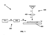
- apparatus 10 for treating a substrate 12 from which undesired material is to be removed includes a radiation system 400, a gas system 500, and a relative motion system 600.
- Irradiation system 400 includes a source 410 of radiation 11 (which consists of energetic photons), such as a laser and suitable delivery optics 450 that conduct radiation 11 to the treatment surface of substrate 12.
- Gas system 500 includes a source 510 of a gas 18 and an associated delivery system 550 for flowing gas 18 over at least the portion of the surface of substrate 12 to which radiation 11 is applied.
- Gas 18 is preferably inert to substrate 12 and is flowed across substrate 12 so as to bathe substrate 12 in a non-reactive gas environment.
- gas 18 is a chemically inert gas such as helium, nitrogen, or argon and is delivered in the laminar flow regime.
- Relative motion system 600 provides for relative motion between a portion of the treatment surface of substrate 12 to be treated and radiation 11 and, optionally, gas 18.
- each of the constituent elements of these components of apparatus 10 may be such as are described in the '258 application and are readily selectable by the artisan to configure the apparatus in accordance with the principles of the invention.
- delivery optics 450 may include mirrors, lenses, optical fibers, collimators, apertures, beam homogenizers, and other elements.
- Gas delivery system 550 may include conduits, chambers, lines, valves, filters, flow meters, and other elements.
- Relative motion system 600 may be any suitable system for translational or rotational movement of substrate 12 with respect to radiation 11 and gas 18, and may include a translational stage for planar translation of the substrate, a rotational fixture for rotating the substrate, or movable components in the delivery optics to scan radiation beam 11 across the substrate. Illustrative embodiments of apparatus 10 are described in more detail below.
- energetic photons are irradiated upon the substrate treatment surface in a spatial and temporal concentration (energy and power fluxes) sufficient to remove undesired material from the substrate treatment surface and insufficient to alter the physical properties of material that is desired to be left on the substrate surface.
- the bonds by which it is adhered to the underlying and adjacent material on the treatment surface must be broken. Each such bond is broken by introducing an amount of energy at least equal to the energy of formation of the bond.
- Bond formation energies i.e., the amount of energy released when the bond is formed
- the bond energies shown are between the material elements themselves (e.g., Cr-Cr) and between the material element and oxygen (e.g., Cr-O). Bond formation energies for various carbon compounds are shown in Table 1b, below.
- oxide bond energies are on the order of 4.0 to 8.3 eV, while organic (carbon) bond energies are on the order of 3.5 to 11.2 eV.
- photon energies of approximately 7 to 22 eV are required.
- a variety of lasers is identified in Table 1c, below. The table identifies the laser medium (and whether the medium is gas (g), liquid (I), solid (s), or plasma (p)), the photon wavelength ⁇ (nm), and the photon energy E ph (eV).
- the total amount of energy (and thus, the total number of photons of a given energy) required to remove a given amount of undesired material from the treatment surface of a substrate is generally proportional to the number of bonds in that amount of material. It is believed that photons interact with bonds only in the interfacial region of the treatment surface (i.e., the topmost one or two layers of atoms or molecules (monolayers)). For removal of substantially continuous layers of material (such as oxide layers) it is therefore helpful to consider unit surface areas and thicknesses of material in monolayers.
- multi-photon bonds there are cases in which the bonds of interest require more energy than is carried by a single photon emitted by the selected radiation source. Such bonds are referred to herein as a "multi-photon bonds.” As noted above, the energies of two or more photons are believed to be additive to supply the energy required to break a multi-photon bond only if the photons strike the bond simultaneously. This implicates the arrival rate of photons at a bond site, which is a power flux (energy per unit time per unit area). Further, it is believed that there is a probabilistic nature to multi-photon bond breaking. For a given average power flux over an area of the substrate, there is an average arrival rate of photons at any given bond site.
- the actual arrival rate of photons should be randomly distributed about the average value.
- a minimum photon arrival rate maximum time interval between the photons
- an average power flux applied to a given area that corresponds to that minimum arrival rate will expose approximately half of the bond sites in that area exposed to the requisite arrival rate (or a greater rate).
- the average power flux is somewhat lower than that required to produce the minimum required photon arrival rate, it is expected that photons will arrive at some of the bond sites within the required interval.
- a minimum total energy flux (a total number of photons of a given energy level per unit area) must be applied to the undesired material. If multi-photon bonds are involved, a certain power flux is also required, and the higher the power flux, the greater the chance that each bond site will be subjected to the requisite photon arrival rate.
- the selection of a suitable source of energetic photons thus requires an evaluation of the required photon energy and, for multi-photon bonds, the available power.
- preferred photon sources are therefore pulsed UV lasers, which have the highest peak power levels and high photon energies.
- changes in the physical properties of a material are caused by increasing the temperature of the material above a threshold level.
- the change in temperature of the surface of a material caused by the application of radiant energy depends on the heat transfer characteristics of the material and the power and energy fluxes of the applied radiation. Finding the maximum power and energy fluxes usable on a given substrate material will require some experimentation.
- Prior art laser cleaning techniques that rely on vaporization, ablation, or surface melting provide some guidance in the energy and power fluxes required to produce surface changes in substrate materials.
- the photons were preferably directed perpendicular to the plane of the portion of the substrate being treated, to maximize the power and energy fluxes at the surface for a given output from the source of photons. It was believed that the only effect of directing photons at an oblique angle was that the energy and power fluxes at the surface would be reduced by a factor corresponding to the sine of the angle of incidence with respect to the plane of the surface. However the invention demonstrates that there are situations where the removal of undesired materials is improved at an oblique angle despite the reduced energy and power fluxes, these reduced fluxes resulting in a lesser probability of damage.
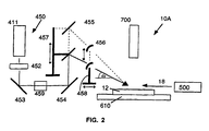
- the radiation source is laser 411, which is a pulsed KrF excimer laser, sold by Lambda Physik as model number LEXtra 200.
- This laser has a wavelength of 248 nm (for a photon energy of 5.01 eV), a maximum output energy per pulse of 600 mJ, and a fixed pulse duration of 34 ns (for a maximum power per pulse of 17.65 MW).
- the maximum pulse repetition rate is 30 Hz, producing a maximum average power of 18 W.
- the radiation beam is 23 mm by 13 mm at the laser output.
- Radiation delivery system 450 includes, in the order encountered by radiation beam 11 upon leaving laser 411, an aperture plate 452, turning mirrors 453, 454, and 455, and cylindrical lens 456.
- Aperture plate 452 can be used to block the "tails" of the Gaussian distribution of photons emanating from laser 411, so that the spatial distribution of energy in radiation beam 11 is approximately uniform across a plane perpendicular to the beam.
- the method used to determine the appropriate aperture dimensions is to allow several laser shots to sufficiently impinge the beam image on facsimile paper. Measurements of the length and width of the beam image are made with a metric dial caliper.
- Turning mirrors 453 - 455 are planar mirrors.
- Mirror 455 can be raised or lowered on mirror support 457 and rotated to adjust the angle of incidence ( Al ), ⁇ , of the beam to the surface of the substrate.
- the smallest incident angle employed in the examples was 6° and the largest was 83.9° -- at greater angles the radiation beam would be reflected back through the radiation delivery system 450. Therefore, normal incidence as discussed in the examples refers to incident angles of approximately 84° relative to the horizontal plane of the treatment surface.
- Cylindrical lens 456 is a 2" x 2" lens having a 200 mm focal length and is sold by Acton Research in Acton, Massachusetts. Cylindrical lens 456 can be raised or lowered on lens support 458 to intercept the beam 11 and moved closer or farther from the substrate to adjust the focus of the beam.
- the cylindrical lens 456 may be adjusted so that the focal plane of the radiation beam 11 is located above (referred to herein as “before focus”) or below (referred to herein as “through focus") the plane of the portion of the substrate being treated. (The effects of before and through focus are discussed bin greater detail in section 4.)
- Mirror 455 and cylindrical lens 456 are held in 5-axis 100 mm gimbal mounts and are adjusted through the use of a micrometer stage.
- the beam width on the surface of the substrate is also adjusted using the micrometer stage.
- element 459 may be added. It may be a polarizer, beamsplitter, or attenuator. All optical elements are anti-reflection coated for 248 nm light. This apparatus can be motorized and automated for computer control.
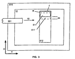
- Radiation beam 11 is delivered in a direction toward stage 610 on which substrate 12 is mounted. As shown in Fig. 3, stage 610 can be translated in the X and Y directions (parallel to the plane of the stage, and indicated in Fig. 3 by arrows X and Y). Radiation beam 11 produces a generally rectangular incident radiation region 611 with a width w and a length l . Region 611 is swept across the surface of substrate 12 by translating stage 610.
- Gas delivery system 500 includes a dewar of liquid nitrogen (4500 l capacity) coupled in series to: a dual stage regulator; a moisture/oxygen adsorber (MG Industries Oxisorb, which adsorbs to concentrations of 0.01 ppb); a Millipore Model 304 particle filter (filters to 0.003 ⁇ m); a flow meter connected to a Cole-Parmer stainless steel mass flow controller, part number H-32561-42 calibrated for nitrogen and inert gas service; a second Millipore Model 304 particle fitter (filters to 0.003 ⁇ m); and thence to a nozzle 551 terminating adjacent region 611.
- a dewar of liquid nitrogen (4500 l capacity) coupled in series to: a dual stage regulator; a moisture/oxygen adsorber (MG Industries Oxisorb, which adsorbs to concentrations of 0.01 ppb); a Millipore Model 304 particle filter (filters to 0.003 ⁇ m); a flow meter connected to a Cole-Parmer stainless steel mass flow
- Nozzle 551 discharges a flow of gas 18 across region 611, and remains fixed with respect to region 611 so that stage 610 and substrate 12 translate with respect to it.
- This gas delivery system is useful for materials that are not sensitive to typical atmospheric gases, and permits a simpler apparatus than is required when it is required or desired to isolate the substrate from the atmosphere during treatment (such as disclosed in the '258 application).
- a video camera 700 is positioned to view region 611 and thus provide visual data on the results of treatment.
- stage 610 is first translated longitudinally in the X direction as radiation beam 11 is applied to the surface of substrate 12, producing an elongated rectangular swath 612 on substrate 12 that has been exposed to radiation beam 12. Stage 610 may be indexed back to a starting position and translated in the X direction again so that radiation beam 12 makes another "pass" over swath 612. After one or more passes, stage 610 may be translated laterally in the Y direction a distance approximately equal to length l , then translated again through the X direction to form another swath adjacent to the previous swath 612. Thus, the portion of the surface of substrate 12 to be treated is sequentially exposed to radiation beam 11 and the concurrent flow of gas 18.
- the energy flux (energy per unit area) applied to any point on the surface of substrate 12 by radiation beam 11 during a single pulse of laser 411 is equal to the energy of the pulse at the surface divided by the area over which that energy is distributed. This can be expressed as: F eps E ps I ⁇ W where F eps is the pulse energy flux per unit area at the surface (J/cm 2 ), E ps is the pulse energy at the surface (J), and l and w are the length and width of region 611 (mm).
- the LEXtra 200 laser includes a mini-controller with a pulse energy meter that is useful for recording the laser energy output during experiments.
- the internal meter is not extremely accurate. To provide more accurate energy measurements, the test apparatus was calibrated to develop a correction factor to be applied to the internal meter reading to produce a more accurate reading.
- the laser pulse energy at the surface ( E ps ) was measured with a Molectron J50 detector head and JD 1000 joulemeter disposed at the location of the treatment surface, and the measured energy reading compared to the internal meter reading of pulse energy ( E pm ).
- a correction factor ( R correction ) was thus developed that included both the losses through the optical train and the meter inaccuracies.
- E ps E pm ⁇ R correction
- This correction factor is not constant -- it has been found to vary approximately linearly with the output level of the laser.
- the pulse energy is dependent on the voltage input ( V I ) to the laser, which can be adjusted to levels between approximately 17 and 22 kV.
- the laser output energy (as indicated by the internal meter) varies for a given voltage setting, depending on such factors as the laser gas supply level, so that the voltage cannot be used directly as a measure of pulse energy, but instead the internal meter is read.
- the correction factor is calculated as a function of the voltage setting, then applied to the energy read from the internal meter.
- a swath 612 is formed from a series of discrete regions 611 (as indicated in Fig. 3 by a second region 611' shown in phantom).
- the distance by which region 611' is offset from region 611 ( ⁇ X ) is the product of the time between laser pulses (which is the inverse of the laser pulse repetition rate R l ) and the velocity of translation of stage 610 (the scan velocity v s ) .
- the energy flux delivered to a given point on the substrate is thus the product of the energy flux per pulse ( F eps ) and the number of laser pulses to which the point is exposed ( N pl ).
- the number of pulses Npl is equal to the width w of region 611 divided by the distance ⁇ X that the stage moves between pulses.
- ⁇ X the distance between pulses.
- the relationship outlined above is reasonably accurate to determine the average energy applied over each swath 612.
- the stage can be left in the same lateral position, and another swath 612 applied in the same place, thus making another "pass" over the substrate.
- the total energy flux delivered ( F et ) is thus equal to the energy flux per pass ( F epa ) times the number of passes ( N pa ).
- the objective was to remove all of the undesired materials in as few passes as possible (preferably in a single pass) and at the highest stage velocity possible, without damaging the treatment surface.
- This corresponds to a maximum processing rate for commercial application -- treating a substrate in the least possible time.
- the key process factors are the energy flux per pulse ( F eps ), the directly related (by the fixed pulse duration of 34 ns) power flux per pulse ( F pps ), and the total energy flux ( F et ).
- F eps the energy flux per pulse
- F pps the power flux per pulse
- F et total energy flux
- These process factors were varied by adjusting the pulse energy ( E ps ), laser pulse repetition rate ( R l ), stage velocity ( V s ), and incident region width ( w ).
- the angle of incidence ( Al ) of the radiation to the treatment surface was varied.
- CMP Chemical Mechanical Polishing
- CMP chemical mechanical polishing
- This example utilized 100 mm wafers that were packaged in a 5% buffing solution in a 150 mm wafer carrier.
- the wafers were patterned to the M1 (Metal 1) layer.
- An aluminum oxide slurry had been used to planarize the surface.
- the wafer samples were both unbuffed and buffed (the buffed samples having less slurry residue on the surface), however no difference in removal efficiency was seen between buffed and unbuffed samples.
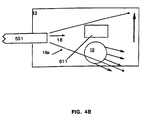
- the wafers were still wet when subjected to the process of the invention. Initially, although the slurry was removed, water streaks remained on the wafer surface after treatment using the configuration illustrated in Fig. 4A, which shows a gas flow expansion zone 18a centered on the radiation region 611.
- gas nozzle 551 is directed slightly ahead of the radiation region 611 so that the flow of gas 18 in the gas flow expansion zone 18a removes the moisture 13 remaining on the wafer prior to the time when the wafer is subjected to the combination of radiation and flowing gas.
- the flow of nitrogen at 44 l/min functioned not only to minimize the re-entrainment of particles but additionally aided in the removal of water streaks created by the wet chemical baths which are part of the CMP process.
- Runs 1-4 were performed with the radiation directed to the surface at an angle of incidence ( Al ) of 83.9°. Runs 1 and 2 both resulted in damage to the substrate. Run 2 had better removal than Run 1, probably because it was performed at higher energy and power fluxes. Element 459 was utilized in Runs 3 and 4. (See Fig. 2) In Run 3 a 50% beam splitter was employed and damage occurred without removing the slurry residue. Run 4 used a polarizer and had a poor result similar to that of Run 3. Run 5 was performed with the radiation directed at angle of 15° with respect to the substrate. While damage was avoided in Run 5 the removal remained poor.
- silicon nitride particles in an aqueous suspension were deposited on bare silicon and allowed to dry. This presented a strongly adhered and very dense contaminant (greater than 10,000 particles on a 150 mm wafer).
- the flowing gas in this example was argon for Run 1 and nitrogen for Runs 2-17. The gas was delivered at approximately 44 Vmin.
- the quantity of contaminant on the substrate before and after treatment was measured by a Particle Measurements Systems (PMS) silicon wafer particle counter Model 3600 XP.
- PMS Particle Measurements Systems
- This particle counter employs two HeNe lasers: one operating in p-polarization and the other in s-polarization with its incident beam at angle of 30° to the wafer plane.
- the collection optics for the particle counter are arranged normal to the wafer plane.
- PR percentage removal
- Runs 1-2 the radiation was directed to the surface at an angle of incidence of 83.9°.
- Runs 1 and 2 utilized non-polarized light and a polarizer was employed in Runs 3 and 4 as element 459. The remaining runs were performed using non-polarized light and were directed at incident angles of 6.5° (Runs 5-10) and 10° (Runs 11-17).
- the average removal over the full range of particle sizes (0.1 - 10 ⁇ m) was 66.1% for the 83.9° incident angle as compared to 80.8% and 72.9% particle removal for angles of incidence of 10° and 6.5°, respectively.
- the 10° angle of incidence appears to be most effective.
- the same relative efficacy is observed for the 0.1 - 0.3 and 0.4 -10 ⁇ m particle size ranges, although the effect is more pronounced for the larger particle sizes.
- polyurethane foam was removed from acrylonitrile-butadiene-styrene terpolymer vinyl upholstery. At approximately normal incidence, 83.9°, the polyurethane foam appeared to melt into the vinyl upholstery in Runs 6 and 7. In contrast, the foam was cleanly removed at a 6° angle of incidence in Runs 1-5. The number of passes, N pa , was dependent on the thickness of the foam attached to the vinyl surface. These results were accomplished at similar fluxes per pass ( F epa ) and somewhat lower fluxes per pulse ( F eps and F pps ). The results of this example are illustrated in Table 3c, below.
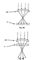
- the focal plane of the cylindrical lens 456 can be focused before or through the plane of the substrate surface being treated. Before and through focus are illustrated in Figs. 5A and 5B, respectively.
Landscapes
- Optics & Photonics (AREA)
- Physics & Mathematics (AREA)
- Engineering & Computer Science (AREA)
- Plasma & Fusion (AREA)
- Mechanical Engineering (AREA)
- Cleaning Or Drying Semiconductors (AREA)
- Analysing Materials By The Use Of Radiation (AREA)
- Drying Of Semiconductors (AREA)
- Laser Beam Processing (AREA)
- Treatments Of Macromolecular Shaped Articles (AREA)
- Polishing Bodies And Polishing Tools (AREA)
- Cleaning In General (AREA)
- Vending Machines For Individual Products (AREA)
- Sampling And Sample Adjustment (AREA)
- Confectionery (AREA)
- Diaphragms For Electromechanical Transducers (AREA)
- Cleaning And De-Greasing Of Metallic Materials By Chemical Methods (AREA)
- Physical Or Chemical Processes And Apparatus (AREA)
- Road Signs Or Road Markings (AREA)
- Shaping Of Tube Ends By Bending Or Straightening (AREA)
Claims (36)
- Verfahren zur Entfernung unerwünschten Materials von einer Bearbeitungsoberfläche eines Substrats (12) ohne Beeinträchtigung der physikalischen Eigenschaften des auf der Bearbeitungsoberfläche zu belassenden gewünschten Materials nahe oder unter dem unerwünschten Material, umfassend die Schritte zur:gekennzeichnet durchBereitstellung eines Substrats (12) mit unerwünschtem Material, das von der Bearbeitungsoberfläche des Substrats (12) zu entfernen ist;Bestrahlung der Bearbeitungsoberfläche mit energiereichen Photonen, um das unerwünschte Material von der Bearbeitungsoberfläche zu lösen;
Einbringen eines Stroms eines Gases (18), das gegenüber dem Substrat (12) und dem unerwünschten Material im Wesentlichen inert ist, quer über das unerwünschte Material bei gleichzeitiger Bestrahlung der Bearbeitungsoberfläche, wobei das eingebrachte Gas (18) die Bearbeitungsoberfläche und das unerwünschte Material in eine reaktionsunfähige Gasumgebung taucht,
dadurch gekennzeichnet, dass
die Bereitstellung eines Substrats (12) mit von dessen Bearbeitungsoberfläche zu entfernendem unerwünschten Material die Bereitstellung eines Substrats (12) mit unerwünschtem Material einschließt, das nicht durch Bestrahlung (11) der Bearbeitungsoberfläche mit energiereichen Photonen entfernt werden kann, die in ungefähr senkrechtem Winkel zur Bearbeitungsoberfläche in einer vorher festgelegten räumlichen und zeitlichen Konzentration auftreffen, die zur Änderung der physikalischen Eigenschaften des gewünschten Materials nicht ausreicht, und
wobei die Bestrahlung der Bearbeitungsoberfläche mit energiereichen Photonen in einem schiefen Winkel von unter ungefähr 20° in der vorher festgelegten räumlichen und zeitlichen Konzentration durchgeführt wird, die zum Herauslösen des unerwünschten Materials aus der Bearbeitungsoberfläche ohne Beeinträchtigung der physikalischen Eigenschaften des auf der Bearbeitungsoberfläche zu belassenden gewünschten Materials ausreicht. - Verfahren nach Anspruch 1, wobei der schiefe Winkel unter ungefähr 10° beträgt.
- Verfahren nach Anspruch 1, wobei das gewünschte Material Silicium ist.
- Verfahren nach Anspruch 3, wobei das unerwünschte Material aus der Gruppe bestehend aus Aluminiumoxid und Siliciumnitrid ausgewählt wird.
- Verfahren nach Anspruch 1, wobei das gewünschte Material Chrom ist.
- Verfahren nach Anspruch 1, wobei das gewünschte Material Acrylnitril-Butadien-Styrol-Terpolymer und das unerwünschte Material Polyurethan ist.
- Verfahren nach Anspruch 1, wobei die energiereichen Photonen eine Energie von ungefähr 5 eV / Photon ausweisen.
- Verfahren nach Anspruch 7, wobei die energiereichen Photonen mit einem gepulsten KrF-Excimerlaser erzeugt werden.
- Verfahren nach Anspruch 1, femer umfassend:als Vorbereitungsschritt - vor dem Schritt der Bestrahlung der Bearbeitungsoberfläche des Substrats (12) mit in schiefem Winkel auftreffenden energiereichen Photonen - die Bestrahlung einer Bearbeitungsoberfläche eines Vorbereitungsschritt-Substrats, das unerwünschtes Material aufweist, welches nach gemeinsamen Merkmalen zu entfernen ist wie beim mit in schiefem Winkel auftreffenden energiereichen Photonen bearbeiteten Substrat (12), durch Zufuhr energiereicher Photonen bei ungefähr senkrechtem Einfallswinkel und gleichzeitiger Zufuhr eines inerten Gases (18) zum Vorbereitungsschritt-Substrat; undeinen Schritt zur Bestimmung, ob das unerwünschte Material entfernt und/oder das Vorbereitungsschritt-Substrat beschädigt wurde.
- Verfahren nach Anspruch 9, wobei die Bestrahlung des Vorbereitungssubstrats und die Bestrahlung des mit in schiefem Winkel auftreffenden energiereichen Photonen bearbeiteten Substrats (12) femer den Durchlauf eines Laserstrahls (11) von einer gemeinsamen Laserstrahlquelle quer über das jeweilige Substrat (12) einschließt, wobei die Energieflüsse pro Puls (Fpps) der energiereichen Photonen für den auf das Vorbereitungssubstrat auftreffenden Laserstrahl (11) größer sind als beim mit in schiefem Winkel auftreffenden energiereichen Photonen bearbeiteten Substrat (12); und wobei der durchschnittliche Energiefluss pro einzelnem Durchlauf des Laserstrahls (Fepa), der auf das Vorbereitungssubstrat trifft, niedriger ist als der Fepa, der auf das mit den energiereichen Photonen in schiefem Winkel bearbeitete Substrat (12) trifft; und wobei der Energiegrad des Laserpulses an der Bearbeitungsoberfläche (Eps), der auf das Vorbereitungssubstrat trifft, niedriger ist als der Eps, der auf das mit in schiefem Winkel auftreffenden energiereichen Photonen bearbeitete Substrat (12) trifft.
- Verfahren nach Anspruch 1, wobei das Einbringen des Gases (18) das Einbringen eines inerten Gases (18) einschließt, das bezogen auf die Bearbeitungsoberfläche und das unerwünschte Material chemisch inert ist.
- Verfahren nach Anspruch 11, wobei das chemisch inerte Gas (18) aus der Gruppe bestehend aus Helium, Stickstoff und Argon ausgewählt wird.
- Verfahren nach Anspruch 1, wobei der schiefe Winkel ungefähr 6° bis 15° beträgt.
- Verfahren nach Anspruch 1, wobei der schiefe Winkel ungefähr 6° bis 10° beträgt.
- Verfahren nach Anspruch 1, wobei der schiefe Winkel ungefähr 6° beträgt.
- Verfahren nach Anspruch 1, wobei der schiefe Winkel ein spitzer Winkel ist.
- Verfahren nach Anspruch 1, wobei der schiefe Winkel auf einen Bereich zwischen 5° und 10° eingestellt ist.
- Verfahren nach Anspruch 1, wobei das Einbringen des Gasstroms das Einbringen des Gases (18) quer über das unerwünschte Material teilweise vor einer Anwendung der Bestrahlungsenergie einschließt, um sowohl eine Trocknungsfunktion vor Einwirkung der energiereichen Strahlen als auch eine Anwendung zur Entfernung des unerwünschten Materials nach Einwirkung der energiereichen Strahlen bereitzustellen.
- Verfahren nach Anspruch 18, wobei der Gasstrom von einer festen Gasstromquelle (510) bereitgestellt wird und die energiereichen Photonen an eine feste Position geleitet werden, während die Bearbeitungsoberfläche relativ zu beiden justiert wird.
- Verfahren nach Anspruch 1, wobei die Bestrahlung der Bearbeitungsoberfläche die Justierung eines Brennpunkts des optischen Wegs eines Laserstrahlgeräts (11) einschließt, um für die energiereichen Photonen einen Brennpunkt bereitzustellen, der sich vor der Ebene des Substrats (12) befindet.
- Verfahren nach Anspruch 1, wobei die Bestrahlung der Bearbeitungsoberfläche die Justierung eines Brennpunkts des optischen Wegs eines Laserstrahlgeräts (11) einschließt, um für die energiereichen Photonen einen Brennpunkt bereitzustellen, der durch die Ebene des Substrats (12) geht oder sich darunter befindet.
- Vorrichtung zur Entfernung unerwünschten Materials von einer Bearbeitungsoberfläche eines Substrats (12) ohne Beinträchtigung der physikalischen Eigenschaften des auf der Bearbeitungsoberfläche zu belassenden gewünschten Materials nahe oder unter dem unerwünschten Material, wobei die Vorrichtung einen Substratträger (610) und ein Bestrahlungssystem (400) zum Leiten der Bestrahlung eines auf dem Substratträger (610) gehaltenen Substrats (12) aufweist,
gekennzeichnet durch
ein Gaszufuhrsystem (550), das gleichzeitig mit dem Leiten der Bestrahlung des auf dem Substratträger gehaltenen Substrats (12) den Strom eines Gases (18) einbringt, das gegenüber dem Substrat (12) und dem unerwünschten Material im Wesentlichen inert ist, wobei das eingebrachte Gas die Bearbeitungsoberfläche und das unerwünschte Material in eine reaktionsunfähige Gasumgebung taucht, während die Bestrahlung der Bearbeitungsoberfläche geleitet wird, und
eine Anpassung des Bestrahlungssystems (400), das zum Leiten der Bestrahlung eines auf dem Substratträger (610) gehaltenen Substrats (12) für einen schiefen Winkel unter 20° auszulegen ist. - Vorrichtung nach Anspruch 22, wobei das Bestrahlungssystem (400) einen Laser und einen im Weg der vom Laser (411) ausgehenden Bestrahlung (11) positionierten Drehspiegel (453, 454, 455) einschließt; und wobei das Bestrahlungssystem (400) femer eine Drehspiegelhalterung (457) einschließt, die justierbar den Drehspiegel (453, 454, 455) so hält, dass dieser zumindest in vertikaler Richtung eingestellt werden kann.
- Vorrichtung nach Anspruch 23, wobei das Bestrahlungssystem (400) femer eine Zylinderlinse (456), die im Weg der vom Laser (411) ausgehenden Bestrahlung (11) liegt, und eine Zylinderlinsenhalterung (458) umfasst, die Mittel einschließt, um die Zylinderlinse (456) vertikal und außerdem entlang einer horizontalen Achse zu justieren, um den Brennpunkt der Bestrahlung (11) relativ zum Substratträger (610) veränderbar zu einer Stelle zu leiten, die innerhalb der Zone unter oder über der Ebene des Substrats (12) liegt.
- Vorrichtung nach Anspruch 22, wobei das Bestrahlung in schiefem Winkel bereitstellende Bestrahlungssystem (400) und das Gas bereitstellende Gaszufuhrsystem (510) relativ zur Bearbeitungsoberfläche so angeordnet sind, dass eine Vortrocknung des unerwünschten Materials und der Bearbeitungsoberfläche unmittelbar vor der Bestrahlung des unerwünschten Materials entlang mehrerer Bestrahlungsstellen der Bearbeitungsoberfläche bereitgestellt wird.
- Vorrichtung nach Anspruch 22, femer umfassend Justiermittel für den Substratträger (610), um diesen entlang einer durch eine X- und Y-Achse dargestellten horizontalen Ebene einzustellen.
- Vorrichtung nach Anspruch 26, wobei die Justiermittel des Substratträgers (610) die Halterung des Substratträgers (610) zuerst entlang einer der X-und Y-Achsen und anschließend entlang der anderen Richtung der X- und Y-Achsen verschiebt.
- Vorrichtung nach Anspruch 26, wobei die X-Achse quer zur Richtung der Bestrahlung des Substrats (12) verläuft und das Gaszufuhrsystem (510) eine Düse (551) mit einer Mittelachse einschließt, die so positioniert ist, dass zumindest ein Teil des ausströmenden Gases (18) vor der auf das Substrat (12) auftreffenden Bestrahlung (11) bleibt, um vor der Bestrahlungsbearbeitung eine Trocknungsfunktion für das Substrat (12) bereitzustellen.
- Vorrichtung nach Anspruch 25, wobei das Bestrahlungssystem (400) an einer festen Position einen Laserstrahl (11) auf die Bearbeitungsoberfläche wirft, während das Substrat (12) durch die Justiermittel des Substratträgers (610) relativ zum festen Gasstrom und zur Bearbeitungsoberflächenposition, auf die der feste Laserstrahl trifft, bewegt wird.
- Vorrichtung nach Anspruch 22, wobei das Gaszufuhrsystem (550) das Gas (18) in Gegenstromrichtung bezogen auf die Richtung der auf das Substrat (12) treffenden Bestrahlung leitet.
- Vorrichtung nach Anspruch 22, wobei das Bestrahlungssysatem (400) Mittel zur Justierung des Einfallswinkels der Bestrahlung (11), die auf einen Teil des Substrats (12) auf dem Substraträger (610) trifft, und Mittel zum Verschieben des Substratträgers (610) relativ zur auftreffenden Bestrahlung einschließt, um eine Materialabtragsfläche (612) auf dem Substrat zu entfernen.
- Vorrichtung nach Anspruch 31, wobei die Justiermittel Mittel zur Veränderung des Einfallswinkels in einem Bereich von 5-10° einschließen.
- Vorrichtung nach Anspruch 32, wobei die Justiermittel Veränderungen des Einfallswinkels in Schritten einschließen, die ein Zehntel des Winkels betragen.
- Vorrichtung nach Anspruch 22, wobei das Gaszufuhrsystem (550) eine Quelle des inerten Gases (510) einschließt, das gegenüber der Bearbeitungsoberfläche und dem unerwünschten Material chemisch inert ist.
- Vorrichtung nach Anspruch 34, wobei das chemisch inerte Gas (18) aus der Gruppe bestehend aus Helium, Stickstoff und Argon ausgewählt wird.
- Vorrichtung nach Anspruch 22, ferner umfassend eine Kombination aus Substrat und unerwünschtem Material, bei der das unerwünschte Material nicht entfernbar oder nur bei Veränderung der physikalischen Eigenschaften des Substrats (12) entfernbar ist, wenn die vom Bestrahlungssystem (400) ausgehende Energie ungefähr senkrecht auftrifft.
Applications Claiming Priority (3)
| Application Number | Priority Date | Filing Date | Title |
|---|---|---|---|
| US686523 | 1996-07-26 | ||
| US08/686,523 US5800625A (en) | 1996-07-26 | 1996-07-26 | Removal of material by radiation applied at an oblique angle |
| PCT/US1997/013317 WO1998004366A1 (en) | 1996-07-26 | 1997-07-22 | Removal of material by radiation applied at an oblique angle |
Publications (2)
| Publication Number | Publication Date |
|---|---|
| EP0921871A1 EP0921871A1 (de) | 1999-06-16 |
| EP0921871B1 true EP0921871B1 (de) | 2003-06-04 |
Family
ID=24756659
Family Applications (1)
| Application Number | Title | Priority Date | Filing Date |
|---|---|---|---|
| EP97937055A Expired - Lifetime EP0921871B1 (de) | 1996-07-26 | 1997-07-22 | Entfernung von material durch in schiefem winkel angewendete strahlung |
Country Status (17)
| Country | Link |
|---|---|
| US (1) | US5800625A (de) |
| EP (1) | EP0921871B1 (de) |
| JP (1) | JP2000515811A (de) |
| KR (1) | KR100476814B1 (de) |
| CN (1) | CN1231623A (de) |
| AT (1) | ATE242065T1 (de) |
| AU (1) | AU3966397A (de) |
| BR (1) | BR9710764A (de) |
| CZ (1) | CZ19899A3 (de) |
| DE (1) | DE69722633T2 (de) |
| EA (1) | EA199900160A1 (de) |
| HU (1) | HUP9903927A3 (de) |
| LV (1) | LV12345A (de) |
| MY (1) | MY113873A (de) |
| NO (1) | NO990150L (de) |
| TW (1) | TW388075B (de) |
| WO (1) | WO1998004366A1 (de) |
Families Citing this family (49)
| Publication number | Priority date | Publication date | Assignee | Title |
|---|---|---|---|---|
| JPH10244392A (ja) * | 1997-03-04 | 1998-09-14 | Semiconductor Energy Lab Co Ltd | レーザー照射装置 |
| US6494217B2 (en) * | 1998-03-12 | 2002-12-17 | Motorola, Inc. | Laser cleaning process for semiconductor material and the like |
| AU5408999A (en) * | 1998-05-26 | 1999-12-13 | Schering Aktiengesellschaft | Treatment of infertility with camp-increasing compounds alone or in combination with at least one meiosis-stimulating compound |
| US7649153B2 (en) * | 1998-12-11 | 2010-01-19 | International Business Machines Corporation | Method for minimizing sample damage during the ablation of material using a focused ultrashort pulsed laser beam |
| US6333485B1 (en) * | 1998-12-11 | 2001-12-25 | International Business Machines Corporation | Method for minimizing sample damage during the ablation of material using a focused ultrashort pulsed beam |
| DE19964443B4 (de) * | 1999-04-07 | 2007-08-16 | Shell Solar Gmbh | Vorrichtung zum Abtragen von Schichten auf einem Werkstück |
| US6881687B1 (en) | 1999-10-29 | 2005-04-19 | Paul P. Castrucci | Method for laser cleaning of a substrate surface using a solid sacrificial film |
| US6582857B1 (en) | 2000-03-16 | 2003-06-24 | International Business Machines Corporation | Repair of masks to promote adhesion of patches |
| US20020029956A1 (en) * | 2000-07-24 | 2002-03-14 | Allen Susan Davis | Method and apparatus for removing minute particles from a surface |
| AU2001282862A1 (en) * | 2000-07-24 | 2002-02-05 | Florida State University Research Foundation | Method and apparatus for removing minute particles from a surface |
| US6805751B2 (en) * | 2000-07-24 | 2004-10-19 | Alkansas State University | Method and apparatus for removal of minute particles from a surface using thermophoresis to prevent particle redeposition |
| US6425956B1 (en) * | 2001-01-05 | 2002-07-30 | International Business Machines Corporation | Process for removing chemical mechanical polishing residual slurry |
| US6635845B2 (en) * | 2001-05-19 | 2003-10-21 | Imt Co., Ltd. | Dry surface cleaning apparatus using a laser |
| US20030062126A1 (en) * | 2001-10-03 | 2003-04-03 | Scaggs Michael J. | Method and apparatus for assisting laser material processing |
| AU2003244399A1 (en) * | 2002-02-01 | 2003-09-02 | Samuel W. Bross | Method and apparatus for cleaning with electromagnetic radiation |
| WO2004011181A2 (en) * | 2002-07-25 | 2004-02-05 | Arkansas State University | Method and apparatus for removing minute particle(s) from a surface |
| KR20040016406A (ko) * | 2002-08-15 | 2004-02-21 | 호야 가부시키가이샤 | 광 모듈 |
| US6852946B2 (en) * | 2002-12-20 | 2005-02-08 | Caterpillar Inc | Laser-induced plasma micromachining |
| US6747243B1 (en) | 2002-12-24 | 2004-06-08 | Novellus Systems, Inc. | Spot cleaning of particles after inspection |
| US7006222B2 (en) * | 2003-01-08 | 2006-02-28 | Kla-Tencor Technologies Corporation | Concurrent measurement and cleaning of thin films on silicon-on-insulator (SOI) |
| US7247986B2 (en) * | 2003-06-10 | 2007-07-24 | Samsung Sdi. Co., Ltd. | Organic electro luminescent display and method for fabricating the same |
| US7341695B1 (en) * | 2003-12-16 | 2008-03-11 | Stuart Garner | Anti-fouling apparatus and method |
| DE102005020072B4 (de) * | 2005-04-22 | 2007-12-06 | Forschungsverbund Berlin E.V. | Verfahren zum Feinpolieren/-strukturieren wärmeempfindlicher dielektrischer Materialien mittels Laserstrahlung |
| DE202005021296U1 (de) * | 2005-05-27 | 2007-10-04 | Emag Laser Tec Gmbh | Vorrichtung zur Behandlung von Werkstückoberflächen |
| US20070022623A1 (en) * | 2005-07-29 | 2007-02-01 | Board Of Regents Of University Of Nebraska | Laser surface drying |
| JP2008073760A (ja) * | 2006-09-25 | 2008-04-03 | Sumitomo Electric Ind Ltd | 付着物除去方法 |
| US20100183987A1 (en) * | 2006-12-08 | 2010-07-22 | Canon Kabushiki Kaisha | Exposure apparatus |
| JP5202876B2 (ja) * | 2007-06-06 | 2013-06-05 | 日東電工株式会社 | レーザー加工方法及びレーザー加工品 |
| US8002899B2 (en) * | 2008-09-30 | 2011-08-23 | Applied Materials, Inc. | Method and apparatus for mask pellicle adhesive residue cleaning |
| US9563137B2 (en) | 2009-06-23 | 2017-02-07 | Asml Netherlands B.V. | Lithographic apparatus and device manufacturing method |
| US8310670B2 (en) * | 2009-07-08 | 2012-11-13 | Universidade De Vigo | Method for removal of wax from porous stones in historical monuments |
| JP2011085642A (ja) * | 2009-10-13 | 2011-04-28 | Hitachi High-Technologies Corp | Fpdパネル実装装置及び実装方法 |
| US20120132629A1 (en) * | 2010-11-30 | 2012-05-31 | Electro Scientific Industries, Inc. | Method and apparatus for reducing taper of laser scribes |
| CN102380491A (zh) * | 2011-08-01 | 2012-03-21 | 迪普干冰制造(大连)有限公司 | 一种加热吸尘搭配干冰清洗的表面脱漆处理设备及方法 |
| KR101507215B1 (ko) * | 2013-02-07 | 2015-03-30 | 주식회사 아이엠티 | 유리 단차부 이물의 건식 세정 방법 및 장치 |
| CN203936519U (zh) * | 2014-05-30 | 2014-11-12 | 宁德新能源科技有限公司 | 锂离子电池极片涂层清洗装置 |
| US10906130B2 (en) * | 2014-06-19 | 2021-02-02 | Magna International Inc. | Method and apparatus for laser assisted power washing |
| WO2017109544A1 (fr) * | 2015-12-22 | 2017-06-29 | Arcelormittal | Procede de preparation d'une tole pre-revetue, avec enlevement du revetement a l'aide d'un faisceau laser incline; tôle correspondante |
| CN105772447B (zh) * | 2016-05-17 | 2019-02-22 | 上海临仕激光科技有限公司 | 一种铝合金氧化膜焊前激光清洗的方法 |
| CN106391591B (zh) * | 2016-11-29 | 2019-11-22 | 苏州热工研究院有限公司 | 激光工作头及激光清洗系统 |
| CN107695040B (zh) * | 2017-10-20 | 2021-01-15 | 大族激光科技产业集团股份有限公司 | 激光清洗系统及方法 |
| CN108554936A (zh) * | 2018-04-08 | 2018-09-21 | 苏州珮凯科技有限公司 | 半导体8寸晶元薄膜制程的e-max工艺的石英零部件的再生方法 |
| US11467508B2 (en) | 2018-07-25 | 2022-10-11 | Applied Materials, Inc. | Pellicle adhesive residue removal system and methods |
| CN109226096A (zh) * | 2018-08-15 | 2019-01-18 | 中车青岛四方机车车辆股份有限公司 | 一种Al-Mg-Zn合金工件表面激光清洗工艺 |
| CN111463122B (zh) * | 2020-04-20 | 2021-04-20 | 天津大学 | 基于极紫外光的原子级材料可控去除方法 |
| CN113690280B (zh) * | 2021-08-11 | 2023-11-28 | 深圳市华星光电半导体显示技术有限公司 | 阵列基板的修复方法和阵列基板 |
| CN114378052B (zh) * | 2021-12-13 | 2023-04-11 | 海目星激光智能装备(江苏)有限公司 | 一种极片清洗系统以及方法 |
| CN115301636A (zh) * | 2022-08-12 | 2022-11-08 | 阳程科技股份有限公司 | 激光除胶方法及采用该方法的除胶设备 |
| CN118253509B (zh) * | 2024-05-29 | 2024-08-30 | 浙江珏芯微电子有限公司 | 一种去除杜瓦内部多余物的装置及吸附体的制备方法 |
Family Cites Families (13)
| Publication number | Priority date | Publication date | Assignee | Title |
|---|---|---|---|---|
| US5643472A (en) * | 1988-07-08 | 1997-07-01 | Cauldron Limited Partnership | Selective removal of material by irradiation |
| US5531857A (en) * | 1988-07-08 | 1996-07-02 | Cauldron Limited Partnership | Removal of surface contaminants by irradiation from a high energy source |
| US5024968A (en) * | 1988-07-08 | 1991-06-18 | Engelsberg Audrey C | Removal of surface contaminants by irradiation from a high-energy source |
| US5099557A (en) * | 1988-07-08 | 1992-03-31 | Engelsberg Audrey C | Removal of surface contaminants by irradiation from a high-energy source |
| US4987286A (en) * | 1989-10-30 | 1991-01-22 | University Of Iowa Research Foundation | Method and apparatus for removing minute particles from a surface |
| US5023424A (en) * | 1990-01-22 | 1991-06-11 | Tencor Instruments | Shock wave particle removal method and apparatus |
| US5281798A (en) * | 1991-12-24 | 1994-01-25 | Maxwell Laboratories, Inc. | Method and system for selective removal of material coating from a substrate using a flashlamp |
| US5204517A (en) * | 1991-12-24 | 1993-04-20 | Maxwell Laboratories, Inc. | Method and system for control of a material removal process using spectral emission discrimination |
| US5319183A (en) * | 1992-02-18 | 1994-06-07 | Fujitsu Limited | Method and apparatus for cutting patterns of printed wiring boards and method and apparatus for cleaning printed wiring boards |
| DE69325171D1 (de) * | 1992-03-31 | 1999-07-08 | Cauldron Lp | Entfernung von oberflächen-verseuchungen durch ausstrahlung |
| AU7682594A (en) * | 1993-09-08 | 1995-03-27 | Uvtech Systems, Inc. | Surface processing |
| FR2711557B1 (fr) * | 1993-10-26 | 1996-01-05 | Saint Gobain Emballage | Procédé et dispositif pour le nettoyage d'éléments solides. |
| IL115933A0 (en) * | 1995-11-09 | 1996-01-31 | Oramir Semiconductor Ltd | Process and apparatus for oblique beam revolution for the effective laser stripping of sidewalls |
-
1996
- 1996-07-26 US US08/686,523 patent/US5800625A/en not_active Expired - Fee Related
- 1996-08-26 MY MYPI96003521A patent/MY113873A/en unknown
- 1996-10-11 TW TW085112434A patent/TW388075B/zh not_active IP Right Cessation
-
1997
- 1997-07-22 BR BR9710764A patent/BR9710764A/pt not_active Application Discontinuation
- 1997-07-22 CN CN97198187A patent/CN1231623A/zh active Pending
- 1997-07-22 WO PCT/US1997/013317 patent/WO1998004366A1/en not_active Ceased
- 1997-07-22 EA EA199900160A patent/EA199900160A1/ru unknown
- 1997-07-22 KR KR10-1999-7000590A patent/KR100476814B1/ko not_active Expired - Fee Related
- 1997-07-22 AU AU39663/97A patent/AU3966397A/en not_active Abandoned
- 1997-07-22 JP JP10509094A patent/JP2000515811A/ja active Pending
- 1997-07-22 EP EP97937055A patent/EP0921871B1/de not_active Expired - Lifetime
- 1997-07-22 AT AT97937055T patent/ATE242065T1/de not_active IP Right Cessation
- 1997-07-22 DE DE69722633T patent/DE69722633T2/de not_active Expired - Fee Related
- 1997-07-22 CZ CZ99198A patent/CZ19899A3/cs unknown
- 1997-07-22 HU HU9903927A patent/HUP9903927A3/hu unknown
-
1999
- 1999-01-13 NO NO990150A patent/NO990150L/no unknown
- 1999-02-23 LV LV990031A patent/LV12345A/xx unknown
Also Published As
| Publication number | Publication date |
|---|---|
| BR9710764A (pt) | 1999-08-17 |
| LV12345A (lv) | 1999-09-20 |
| EA199900160A1 (ru) | 1999-08-26 |
| ATE242065T1 (de) | 2003-06-15 |
| DE69722633T2 (de) | 2004-04-29 |
| HU9903927A (en) | 2000-04-28 |
| CZ19899A3 (cs) | 1999-09-15 |
| HUP9903927A3 (en) | 2000-05-29 |
| JP2000515811A (ja) | 2000-11-28 |
| TW388075B (en) | 2000-04-21 |
| US5800625A (en) | 1998-09-01 |
| NO990150L (no) | 1999-03-02 |
| NO990150D0 (no) | 1999-01-13 |
| WO1998004366A1 (en) | 1998-02-05 |
| DE69722633D1 (de) | 2003-07-10 |
| EP0921871A1 (de) | 1999-06-16 |
| CN1231623A (zh) | 1999-10-13 |
| MY113873A (en) | 2002-06-29 |
| KR100476814B1 (ko) | 2005-03-18 |
| KR20000029533A (ko) | 2000-05-25 |
| AU3966397A (en) | 1998-02-20 |
Similar Documents
| Publication | Publication Date | Title |
|---|---|---|
| US5800625A (en) | Removal of material by radiation applied at an oblique angle | |
| EP0782483B1 (de) | Selektive entfernung von material durch bestrahlung | |
| EP0834191B1 (de) | Materialentfernung durch polarisierte strahlung und rückseitige anwendung von strahlung | |
| US6048588A (en) | Method for enhancing chemisorption of material | |
| EP0350021B1 (de) | Entfernung von Oberflächen-Verseuchungen durch Ausstrahlung aus einer Hoch-Energiequelle | |
| US5821175A (en) | Removal of surface contaminants by irradiation using various methods to achieve desired inert gas flow over treated surface | |
| EP0693978B1 (de) | Entfernung von oberflächen-verschmutzungen durch bestrahlung | |
| JPH07505577A (ja) | 照射による表面汚染物の除去 | |
| US20040224508A1 (en) | Apparatus and method for cleaning a substrate using a homogenized and non-polarized radiation beam | |
| CA2259910C (en) | Removal of material by radiation applied at an oblique angle | |
| MXPA97002097A (es) | Eliminacion selectiva de material por medio de irradiac | |
| HK1004944B (en) | Method and device for selectively removing undesired material by irradiation |
Legal Events
| Date | Code | Title | Description |
|---|---|---|---|
| PUAI | Public reference made under article 153(3) epc to a published international application that has entered the european phase |
Free format text: ORIGINAL CODE: 0009012 |
|
| 17P | Request for examination filed |
Effective date: 19990219 |
|
| AK | Designated contracting states |
Kind code of ref document: A1 Designated state(s): AT BE CH DE DK ES FI FR GB GR IE IT LI LU NL SE |
|
| 17Q | First examination report despatched |
Effective date: 20010502 |
|
| GRAH | Despatch of communication of intention to grant a patent |
Free format text: ORIGINAL CODE: EPIDOS IGRA |
|
| GRAH | Despatch of communication of intention to grant a patent |
Free format text: ORIGINAL CODE: EPIDOS IGRA |
|
| GRAA | (expected) grant |
Free format text: ORIGINAL CODE: 0009210 |
|
| AK | Designated contracting states |
Designated state(s): AT BE CH DE DK ES FI FR GB GR IE IT LI LU NL SE |
|
| PG25 | Lapsed in a contracting state [announced via postgrant information from national office to epo] |
Ref country code: NL Free format text: LAPSE BECAUSE OF FAILURE TO SUBMIT A TRANSLATION OF THE DESCRIPTION OR TO PAY THE FEE WITHIN THE PRESCRIBED TIME-LIMIT Effective date: 20030604 Ref country code: LI Free format text: LAPSE BECAUSE OF FAILURE TO SUBMIT A TRANSLATION OF THE DESCRIPTION OR TO PAY THE FEE WITHIN THE PRESCRIBED TIME-LIMIT Effective date: 20030604 Ref country code: IT Free format text: LAPSE BECAUSE OF FAILURE TO SUBMIT A TRANSLATION OF THE DESCRIPTION OR TO PAY THE FEE WITHIN THE PRESCRIBED TIME-LIMIT;WARNING: LAPSES OF ITALIAN PATENTS WITH EFFECTIVE DATE BEFORE 2007 MAY HAVE OCCURRED AT ANY TIME BEFORE 2007. THE CORRECT EFFECTIVE DATE MAY BE DIFFERENT FROM THE ONE RECORDED. Effective date: 20030604 Ref country code: FI Free format text: LAPSE BECAUSE OF FAILURE TO SUBMIT A TRANSLATION OF THE DESCRIPTION OR TO PAY THE FEE WITHIN THE PRESCRIBED TIME-LIMIT Effective date: 20030604 Ref country code: CH Free format text: LAPSE BECAUSE OF FAILURE TO SUBMIT A TRANSLATION OF THE DESCRIPTION OR TO PAY THE FEE WITHIN THE PRESCRIBED TIME-LIMIT Effective date: 20030604 Ref country code: BE Free format text: LAPSE BECAUSE OF FAILURE TO SUBMIT A TRANSLATION OF THE DESCRIPTION OR TO PAY THE FEE WITHIN THE PRESCRIBED TIME-LIMIT Effective date: 20030604 Ref country code: AT Free format text: LAPSE BECAUSE OF FAILURE TO SUBMIT A TRANSLATION OF THE DESCRIPTION OR TO PAY THE FEE WITHIN THE PRESCRIBED TIME-LIMIT Effective date: 20030604 |
|
| REG | Reference to a national code |
Ref country code: GB Ref legal event code: FG4D |
|
| REG | Reference to a national code |
Ref country code: CH Ref legal event code: EP |
|
| REG | Reference to a national code |
Ref country code: IE Ref legal event code: FG4D |
|
| REF | Corresponds to: |
Ref document number: 69722633 Country of ref document: DE Date of ref document: 20030710 Kind code of ref document: P |
|
| PG25 | Lapsed in a contracting state [announced via postgrant information from national office to epo] |
Ref country code: LU Free format text: LAPSE BECAUSE OF NON-PAYMENT OF DUE FEES Effective date: 20030722 Ref country code: IE Free format text: LAPSE BECAUSE OF NON-PAYMENT OF DUE FEES Effective date: 20030722 |
|
| PG25 | Lapsed in a contracting state [announced via postgrant information from national office to epo] |
Ref country code: SE Free format text: LAPSE BECAUSE OF FAILURE TO SUBMIT A TRANSLATION OF THE DESCRIPTION OR TO PAY THE FEE WITHIN THE PRESCRIBED TIME-LIMIT Effective date: 20030904 Ref country code: GR Free format text: LAPSE BECAUSE OF FAILURE TO SUBMIT A TRANSLATION OF THE DESCRIPTION OR TO PAY THE FEE WITHIN THE PRESCRIBED TIME-LIMIT Effective date: 20030904 Ref country code: DK Free format text: LAPSE BECAUSE OF FAILURE TO SUBMIT A TRANSLATION OF THE DESCRIPTION OR TO PAY THE FEE WITHIN THE PRESCRIBED TIME-LIMIT Effective date: 20030904 |
|
| PG25 | Lapsed in a contracting state [announced via postgrant information from national office to epo] |
Ref country code: ES Free format text: LAPSE BECAUSE OF FAILURE TO SUBMIT A TRANSLATION OF THE DESCRIPTION OR TO PAY THE FEE WITHIN THE PRESCRIBED TIME-LIMIT Effective date: 20030915 |
|
| NLV1 | Nl: lapsed or annulled due to failure to fulfill the requirements of art. 29p and 29m of the patents act | ||
| REG | Reference to a national code |
Ref country code: CH Ref legal event code: PL |
|
| ET | Fr: translation filed | ||
| PLBE | No opposition filed within time limit |
Free format text: ORIGINAL CODE: 0009261 |
|
| STAA | Information on the status of an ep patent application or granted ep patent |
Free format text: STATUS: NO OPPOSITION FILED WITHIN TIME LIMIT |
|
| REG | Reference to a national code |
Ref country code: IE Ref legal event code: MM4A |
|
| 26N | No opposition filed |
Effective date: 20040305 |
|
| PGFP | Annual fee paid to national office [announced via postgrant information from national office to epo] |
Ref country code: DE Payment date: 20070719 Year of fee payment: 11 |
|
| PGFP | Annual fee paid to national office [announced via postgrant information from national office to epo] |
Ref country code: GB Payment date: 20070718 Year of fee payment: 11 |
|
| PGFP | Annual fee paid to national office [announced via postgrant information from national office to epo] |
Ref country code: FR Payment date: 20070725 Year of fee payment: 11 |
|
| GBPC | Gb: european patent ceased through non-payment of renewal fee |
Effective date: 20080722 |
|
| PG25 | Lapsed in a contracting state [announced via postgrant information from national office to epo] |
Ref country code: DE Free format text: LAPSE BECAUSE OF NON-PAYMENT OF DUE FEES Effective date: 20090203 |
|
| REG | Reference to a national code |
Ref country code: FR Ref legal event code: ST Effective date: 20090331 |
|
| PG25 | Lapsed in a contracting state [announced via postgrant information from national office to epo] |
Ref country code: GB Free format text: LAPSE BECAUSE OF NON-PAYMENT OF DUE FEES Effective date: 20080722 |
|
| PG25 | Lapsed in a contracting state [announced via postgrant information from national office to epo] |
Ref country code: FR Free format text: LAPSE BECAUSE OF NON-PAYMENT OF DUE FEES Effective date: 20080731 |