EP0921033B1 - Fahrzeugsitz mit Aufhängungssystem - Google Patents
Fahrzeugsitz mit Aufhängungssystem Download PDFInfo
- Publication number
- EP0921033B1 EP0921033B1 EP98123235A EP98123235A EP0921033B1 EP 0921033 B1 EP0921033 B1 EP 0921033B1 EP 98123235 A EP98123235 A EP 98123235A EP 98123235 A EP98123235 A EP 98123235A EP 0921033 B1 EP0921033 B1 EP 0921033B1
- Authority
- EP
- European Patent Office
- Prior art keywords
- suspension mechanism
- seat cushion
- torsion bar
- moveable
- vehicle seat
- Prior art date
- Legal status (The legal status is an assumption and is not a legal conclusion. Google has not performed a legal analysis and makes no representation as to the accuracy of the status listed.)
- Expired - Lifetime
Links
Images


Classifications
-
- B—PERFORMING OPERATIONS; TRANSPORTING
- B60—VEHICLES IN GENERAL
- B60N—SEATS SPECIALLY ADAPTED FOR VEHICLES; VEHICLE PASSENGER ACCOMMODATION NOT OTHERWISE PROVIDED FOR
- B60N2/00—Seats specially adapted for vehicles; Arrangement or mounting of seats in vehicles
- B60N2/50—Seat suspension devices
- B60N2/502—Seat suspension devices attached to the base of the seat
-
- B—PERFORMING OPERATIONS; TRANSPORTING
- B60—VEHICLES IN GENERAL
- B60N—SEATS SPECIALLY ADAPTED FOR VEHICLES; VEHICLE PASSENGER ACCOMMODATION NOT OTHERWISE PROVIDED FOR
- B60N2/00—Seats specially adapted for vehicles; Arrangement or mounting of seats in vehicles
- B60N2/50—Seat suspension devices
- B60N2/505—Adjustable suspension including height adjustment
-
- B—PERFORMING OPERATIONS; TRANSPORTING
- B60—VEHICLES IN GENERAL
- B60N—SEATS SPECIALLY ADAPTED FOR VEHICLES; VEHICLE PASSENGER ACCOMMODATION NOT OTHERWISE PROVIDED FOR
- B60N2/00—Seats specially adapted for vehicles; Arrangement or mounting of seats in vehicles
- B60N2/50—Seat suspension devices
- B60N2/506—Seat guided by rods
- B60N2/507—Parallelogram-like structure
-
- B—PERFORMING OPERATIONS; TRANSPORTING
- B60—VEHICLES IN GENERAL
- B60N—SEATS SPECIALLY ADAPTED FOR VEHICLES; VEHICLE PASSENGER ACCOMMODATION NOT OTHERWISE PROVIDED FOR
- B60N2/00—Seats specially adapted for vehicles; Arrangement or mounting of seats in vehicles
- B60N2/50—Seat suspension devices
- B60N2/54—Seat suspension devices using mechanical springs
- B60N2/544—Compression or tension springs
-
- B—PERFORMING OPERATIONS; TRANSPORTING
- B60—VEHICLES IN GENERAL
- B60N—SEATS SPECIALLY ADAPTED FOR VEHICLES; VEHICLE PASSENGER ACCOMMODATION NOT OTHERWISE PROVIDED FOR
- B60N2/00—Seats specially adapted for vehicles; Arrangement or mounting of seats in vehicles
- B60N2/50—Seat suspension devices
- B60N2/54—Seat suspension devices using mechanical springs
- B60N2/548—Torsion springs, e.g. torsion helicoidal springs
Definitions
- the present invention relates to a vehicle seat, and more particularly to a vehicle seat with a suspension mechanism for support of a cushion frame and an adjustment mechanism for adjusting a resilient force of the suspension mechanism (see, for example, EP-A-0 319 177, corresponding to the preamble of claim 1).
- a vehicle seat equipped with a suspension mechanism of the type which includes a torsion bar spring assembled for support of a cushion frame.
- a resilient force of the suspension mechanism can be adjusted in accordance with a difference in weight of a passenger seated on a seat cushion to enhance seating comfort of the vehicle seat.
- a reaction force of the torsion bar spring against a load applied thereto is adjusted only to a limited extent. For this reason, a deflection amount of the suspension mechanism is limited as shown by a dotted curve A in Fig. 18. This deteriorates the seating comfort of the vehicle seat and causes a bottomed feel on the seat cushion.
- a primary object of the present invention to provide a vehicle seat equipped with a suspension mechanism the resilient force of which can be adjusted in according with a difference in weight of a passenger seated on a seat cushion.
- a secondary object of the present invention is to provide a vehicle seat equipped with a suspension mechanism in which a set of torsion bar springs is associated with a tension spring to solve the problem in adjustment of the suspension mechanism discussed above.
- the primary object is accomplished by providing a vehicle seat provided with a seat cushion the support frame of which is supported by a suspension mechanism, wherein the suspension mechanism includes a torsion bar spring loaded to resiliently support the support frame of the seat cushion, and wherein a spring adjustment mechanism is assembled with the suspension mechanism for adjusting the resilient force of the torsion bar spring.
- the spring adjustment mechanism includes a moveable bracket pivotally mounted on a support structure placed on a floor of a vehicle compartment to be rotated in a vertical direction and an adjustment mechanism for adjusting the rotation amount of the moveable bracket, and wherein the torsion bar spring of the suspension mechanism is supported at one end thereof on the support structure and is carried by the moveable bracket at the other end thereof to resiliently support the support frame of the seat cushion.
- the spring adjustment mechanism includes an operation arm pivotally mounted on the support structure to be rotated in a vertical direction and being connected with the moveable bracket to move the moveable bracket therewith when rotated in the vertical direction, an operation shaft supported from the support frame of the seat cushion to be rotated by operation of a handle fixed to its outer end, a moveable member mounted on the operation shaft to be moved forward or backward by rotation of the operation shaft, a swing arm pivoted at its intermediate portion to the support frame of the seat cushion and connected at its one end to the moveable member, and an operation wire connected at its one end to the other end of the swing arm and at its other end to the operation arm.
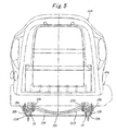
- a vehicle seat composed of a seat cushion 10a and a backrest 10b. As shown in Figs. 1 and 3, the vehicle seat is equipped with a suspension mechanism 20 and a spring adjustment mechanism 30.
- the same reference numerals designate the same component parts and portions of the vehicle seat.
- the backrest 10b is integrally formed with a headrest and is assembled at its lower end with a rear portion of a support frame 10c of the seat cushion 10a shown in Fig. 7 to be retained in an upright position behind the seat cushion 10a.
- the cushion frame 10c is in the form of a rectangular frame structure 11 which is integrally provided at its rear end with a pair of upright brackets 12a and 12b to be assembled with a frame structure of the backrest 10b.
- the cushion frame 10c is mounted on a pair of parallel seat tracks 13 through the suspension mechanism 20.
- the pair of seat tracks 13 each are composed of a lower rail 13a and an upper rail 13b.
- the lower rails 13a are mounted in parallel on a floor of a vehicle compartment in a fore-and-aft direction.
- the upper rails 13b are slidably coupled with the lower rails 13a and locked to the lower rails 13a in a desired position by means of a pair of locking mechanisms 14.
- the locking mechanisms 14 each are constructed to release the upper rails 13b from the lower rails 13a by operation of a release lever 14a illustrated by imaginary lines in the figure. In a condition where the locking mechanisms 14 have been released by operation of the release levers 14a, the upper rails 13a can be moved along the lower rails 13b for adjustment of the seating position of the vehicle seat.
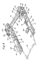
- the suspension mechanism 20 includes a pair of moveable brackets 21a, 21b, a pair of rear link members 22a, 22b, the pair of torsion bar springs 23a, 23b, a pair of front link'members 24a, 24b, a pair of connecting rods 25a, 25b and a shock absorber 26.
- a pair of base brackets 15a, 15b are fixedly mounted on each rear end of the upper rails 13b.
- the movable brackets 21a, 21b are supported on the base brackets 15a, 15b respectively by means of a support pin 15c to be rotatable in a vertical direction.
- the rear link members 22a, 22b are supported on the base brackets 15a, 15b at their rear ends to be rotatable in a vertical direction.
- the torsion bar springs 23a, 23b are each formed at their one ends with a hooked portion and bent in an L-shape at their other ends.
- the bent portions of the torsion bar springs 23a, 23b are fixed to the base brackets 15a, 15b respectively, and the hooked portions of the torsion bar springs 23a, 23b are engaged with each elongated hole 22c formed in the rear link members 22a, 22b.
- the torsion bar springs 23a, 23b are carried by clamps 21c fixed to the moveable brackets 21a, 21b.
- the rear link members 22a, 22b are loaded upward by the torsion bar springs 23a, 23b engaged therewith.
- the rear connecting rod 25a is engaged with the front ends of rear link members 22a, 22b for connecting the rear link members 22a, 22b to one another.
- the connecting rod 25a is connected at its opposite ends to the support frame 10c of seat cushion 10a.
- the rotation extent of each of the rear link members 22a, 22b is restricted by engagement with upright flanges 15a1, 15b1 of the base brackets 15a, 15b shown in Fig. 8.
- the front link members 24a, 24b are each rotatably supported on upright flanges of base brackets 15c, 15e fixedly mounted on the upper rails 13b of seat tracks 13. As shown in Fig. 1, the front link members 24a, 24b are connected to one another by means of a front connecting rod 25b fixedly coupled with the front ends thereof.
- the front connecting rod 25b is connected at its opposite ends to the support frame 10c of seat cushion 10a and interconnected with the rear connecting rod 25a by means of a pair of connecting members 25c and each pair of connecting arms 25d, 25e.
- a pair of support brackets 25f are fixed to the rear end portions of connecting members 25c.
- the shock absorber 26 is connected at its rear end to the support bracket 25f and connected at its front end to the front connecting rod 25b by means of a connecting arm 25g.
- the spring adjustment mechanism 30 includes a pair of operation arms 31a, 31b, a rotary shaft 32, a moveable member 33, an operation shaft 34, a pair of swing arms 35a, 35b, and a pair of operation wires 36a, 36b.
- the operation arms 31a, 31b, swing arms 35a, 35b and operation wires 36a, 36b are located under the cushion frame 10c and arranged symmetrically with respect to the rotary shaft 32 and moveable member 33.
- the operation arms 31a, 31b are rotatably supported on the base brackets 15a, 15b respectively by means of a support pin 37a to be moved in a vertical direction and connected to the moveable brackets 21a, 21b of the suspension mechanism 20 respectively by means of a connecting pin 37b.
- the connecting pin 37b is fixed to each moveable end of the operation arms 31a, 31b and is inserted into an elongated hole 21d respectively formed in the movable brackets 21a, 21b.
- the rotary shaft 32 is rotatably supported on a front central portion of the cushion frame 10c, and the moveable member 33 is mounted on the rotary shaft 32 to be moved by rotation of the rotary shaft 32 in a fore-and-aft direction of the vehicle seat.
- the operation shaft 34 is rotatably supported on side and central portions of the cushion frame 10c in a lateral direction and extended outwardly from the side portion of cushion frame 10c.
- the operation shaft 34 is provided with a handle 34a at its outer end and a drive gear 34b at its inner end.
- the drive gear 34b is meshed with a driven gear 32a mounted on the rotary shaft 32 for rotation therewith.
- the swing arms 35a, 35b each are pivoted to the bottom of cushion frame 10c at their intermediate portions by means of a support pin 37c and pivoted to the opposite ends of moveable member 33 at their inner ends by means of a connecting pin 37d.
- the operation wires 36a, 36b are connected to the outer ends of swing arms 35a, 35b at their front ends and to the operation arms 31a, 31b at their rear ends.
- the resiliency of the suspension mechanism 20 can be adjusted by operation of the spring adjustment mechanism 30 to ensure the seating comfort of the vehicle seat in accordance with a difference in weight of a passenger as will described hereinafter.
- the rear link members 22a, 22b of the suspension mechanism 20 are retained in an upper position under the load of torsion bar springs 23a, 23b, while the front link members 24a, 24b are retained in an upper position to maintain the shock absorber 26 in a contracted condition.
- the torsion bar springs 23a, 23b of the suspension mechanism 20 are twisted by the load applied thereto from the seat cushion 10a, and the rear link members 22a, 22b and front link members 24a, 24b are rotated downward as shown in Fig. 2.
- the shock absorber 26 is expanded by forward rotation of the connecting arms 25e and 25g to absorb impact and vibration caused by the load from the seat cushion 10a.
- the resilient force of torsion bar springs 23a, 23b can be adjusted by operation of the handle 34a of the spring adjustment mechanism 30.
- the spring adjustment mechanism 30 is maintained in a condition shown by solid lines in Fig. 6.
- the moveable member 33 is positioned at a front end of rotary shaft 32 so that the outer ends of swing arms 35a, 35b are moved rearward to retain the operation arms 31a, 31b in place.
- the moveable brackets 21a, 21b are retained in a horizontal condition.
- the resilient force of the suspension mechanism can be adjusted by operation of the spring adjustment mechanism in accordance with a difference in weight of a passenger seated on the seat cushion.
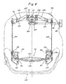
- Fig. 10 Illustrated in Fig. 10 is a vehicle seat composed of a seat cushion 10a, a backrest 10b assembled with a rear end of the seat cushion 10a and placed in an upright position, and an armrest AR assembled with one side of the backrest 10b.
- a support frame 10c of the seat cushion 10a is mounted on a pair of seat tracks 13 through a suspension mechanism 20.
- the vehicle seat is equipped with a spring adjustment mechanism 30 for adjusting the resilient force of the suspension mechanism 20.
- the support frame 10c of seat cushion 10a is in the form of a rectangular structure which is integrally provided at its rear end with a pair of upright brackets 12a and 12b to be assembled with a frame structure (not shown) of the backrest 10b.
- the pair of seat tracks 13 are each composed of a lower rail 13a mounted on a floor of a vehicle compartment in a fore-and-aft direction, an upper rail 13b slidably coupled with the lower rail 13a, and a pair of locking mechanisms 14 for locking the upper rails 13b to the lower rails 13a in a desired position.
- the upper rails 13b each are provided thereon with front and rear base brackets 15a, 15b and 15d, 15e, and a lateral base plate 46 is fixed to the front ends of upper rails 13b at its opposite ends.
- the locking mechanisms 14 mounted on the upper rails 13b are constructed to release the upper rails 13b from the lower rails 13a by operation of a release lever 14a shown by imaginary lines in Fig. 12. When the release lever 14a is operated to release the locking mechanisms 14, the upper rails 13b can be moved along the lower rails 13a for adjustment of the seating position of the vehicle seat.
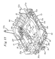
- the suspension mechanism 20 includes a pair of rear link members 22a, 22b, a pair of torsion bar springs 23a, 23b, a pair of front link members 24a, 24b, a pair of connecting rods 25a, 25b, and a tension coil spring 45.
- the rear link members 22a, 22b are supported on the rear base brackets 15a, 15b at their rear ends respectively by means of a support pin 15c to be rotatable in a vertical direction.
- the front link members 24a, 24b are supported on upright flanges of the front base brackets 15d, 15e at their rear ends respectively by means of a support pin 24c to be rotatable in a vertical direction.
- the torsion bar springs 23a, 23b are each formed at their one ends with a hooked portion and bent in an L-shape at their other ends.
- the bent portions of torsion bar springs 23a, 23b are fixed to the rear base brackets 15a, 15b respectively, and the hooked portions of torsion bar springs 23a, 23b are engaged with each elongated hole 22c formed in the rear link members 22a, 22b.
- the torsion bar springs 23a, 23b are carried by clamps 21c fixed to the moveable brackets 21a, 21b.
- the rear link members 22a, 22b are loaded upward by the torsion bar springs 23a, 23b engaged therewith.
- the rear connecting rod 25a is engaged with the front ends of rear link members 22a, 22b for connecting the rear link members 22a, 22b to one another.
- the rear connecting rod 25a is connected at its opposite ends to the cushion frame 10c.
- the rotation extent of each of the rear link members 22a, 22b is restricted by engagement with upright flanges 15a1, 15b1 of the rear base brackets 15a, 15b.
- the front link members 24a, 24b are connected at their front ends to one another by means of the front connecting rod 25b fixedly engaged therewith.
- the front connecting rod 25b is connected at its opposite ends to the cushion frame 10c and interconnected to the rear connecting rod 25b by means of a pair of connecting members 25c and each pair of connecting arms 25d, 25e.
- the tension coil spring 45 is engaged at its front end with a hook 46a fixed to the base plate 46 and at its rear end with a connecting arm 44 fixed to the rear connecting rod 25b.
- the biasing force of tension coil spring 45 is determined to be larger than that of torsion bar springs 23a, 23b.
- the suspension mechanism 20 is provided with a shock absorber 26 which is connected at its front end with a support bracket 25g fixed to the front connecting rod 25b and at its rear end with a support bracket 25f fixed to the connecting member 25c.
- the spring adjustment mechanism 30 includes a pair of operation arms 31a, 31b, an operation shaft 34, a moveable member 33, a pair of swing arms 35a, 35b and a pair of operation wires 36a, 36b.
- the moveable brackets 21a, 21b, operation arms 31a, 31b, swing arms 35a, 35b and operation wires 36a, 36b are located under the cushion frame 10c and arranged symmetrically with respect to the operation shaft 34.
- the movable brackets 21a, 21b are each rotatably supported on the rear base brackets 15a, 15b respectively by means of a support pin 15d to be moved in a vertical direction.
- the operation arms 31a, 31b each are rotatably supported on upright flanges of the rear base brackets 15a, 15b respectively by means of a support pin 37a to be movable in the vertical direction and connected to the movable brackets 21a, 21b respectively by means of a connecting pin 37b.
- the connecting pin 37b is fixed to each movable end of operation arms 31a, 31b and is inserted into an elongated hole 21d respectively formed in the movable brackets 21a, 21b.
- the operation shaft 34 is formed with a threaded portion 34b and provided with a handle 34a.
- the operation shaft 34 is rotatably supported on an upright flange of the base plate 46 and an upright bracket 46b fixed to the base plate 46 to be displaced forward or backward in the fore-and-aft direction of the vehicle seat, and the moveable member 33 is mounted on the threaded portion 34b of operation shaft 34 to be moved forward or backward.
- the operation shaft 34 is extended forward from the cushion frame 10c, and the handle 34a is fixed to the outer end of operation shaft 34.
- the swing arms 35a, 35b are each pivoted to the base plate 46 at their intermediate portions respectively by means of a support pin 37c and pivoted to the opposite ends of moveable member 33 respectively by means of a connecting pin 37d.
- the operation wires 36a, 36b are connected to the outer ends of swing arms 35a, 35b at their front ends and to the operation arms 31a, 31b at their rear ends.
- the suspension mechanism 20 acts to enhance the seating comfort of the vehicle seat, and the resiliency of the suspension mechanism 20 can be adjusted by operation of the spring adjustment mechanism 30 to ensure the seating comfort of the vehicle seat in accordance with a difference in weight of a passenger.
- the rear link members 22a, 22b are retained in an upper position under the load of torsion bar springs 23a, 23b, while the front link members 24a, 24b are retained in an upper position to maintain the shock absorber 26 in a contracted condition.
- the torsion bar springs 23a, 23b of the suspension mechanism 20 are twisted by a load applied thereto from the seat cushion 10a, and the rear link members 22a, 22b and front link members 24a, 24b are rotated downward as shown by imaginary lines in Fig. 15.
- the shock absorber 25 is expanded by forward rotation of the connecting arms 25e and 25g to absorb impact and vibration caused by the load from the seat cushion 10a.
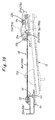
- the connecting arm 44 When the load applied to the seat cushion 10a is less than a predetermined value, the connecting arm 44 is rotated to an extent ranging between positions X and Y shown in Fig. 15. In such an instance, only the resilient force of torsion bar springs 23a, 23b is applied to the seat cushion 10a, and the deflection amount of torsion bar springs 23a, 23b is increased as shown by the solid curve B in Fig. 18.
- the connecting arm 44 is rotated, as mentioned, between positions Y and Z shown in Fig. 15.
- the seating comfort of the vehicle seat is enhanced by adjustment of the resilient force of torsion bar springs 23a, 23b.
- the tension spring 45 cooperates with the torsion bar springs 23a, 23b to resiliently support the seat cushion 10a thereby to enhance the seating comfort of the vehicle seat without causing a bottomed feel on the seat cushion.
- the resilient force of torsion springs 23a, 23b can be adjusted by operation of the handle 34a on the operation shaft 34.
- the spring adjustment mechanism 30 is maintained in a condition shown by solid lines in Fig. 14.
- the moveable member 33 is positioned at a front end of the threaded portion 34b of operation shaft 34 so that the outer ends of swing arms 35a, 35b are moved rearward to retain the moveable brackets 21a, 21b in a horizontal position as shown in Fig. 16.
Claims (3)
- Fahrzeugsitz, der mit einem Sitzpolster (10a) ausgestattet ist, das einen Tragrahmen (10c) aufweist, der durch einen Aufhängemechanismus (20) getragen wird, wobei der Aufhängemechanismus (20) eine Drehstabfeder (23a, 23b) enthält, die zum federnden Tragen des Tragrahmens (10c) des Sitzpolsters belastet ist, und wobei ein Federeinstellmechanismus (30) mit dem Aufhängemechanismus (20) zum Einstellen der Federkraft der Drehstabfeder (23a, 23b) zusammengesetzt ist,
dadurch gekennzeichnet, dass
der Federeinstellmechanismus (30) eine bewegliche Stütze (21a, 21b), die drehbar an einer Tragstruktur (13), die am Boden eines Fahrzeuginnenraums angeordnet ist, zum Drehen der beweglichen Stütze (21a, 21b) in vertikaler Richtung angebracht ist, und einen Einstellmechanismus (31, 31b) zum Einstellen des Ausmaßes der vertikalen Drehung der beweglichen Stütze (21a, 21b) enthält, wobei die Drehstabfeder (23a, 23b) des Aufhängemechanismus (20) zum federnden Tragen des Tragrahmens (10c) des Sitzpolsters an ihrem einen Ende an der Tragstruktur (13) gehalten wird und durch die bewegliche Stütze (21a, 21b) an ihrem anderen Ende gehalten wird. - Fahrzeugsitz nach Anspruch 1, wobei der Federeinstellmechanismus (30) einen Betätigungsarm (31a, 31b), der drehbar an der Tragstruktur (30) zum Drehen der beweglichen Stütze(21a, 21b) in vertikaler Richtung angebracht ist und mit der beweglichen Stütze (21a, 21b) zum Bewirken des vertikalen Drehens der beweglichen Stütze (21 a, 21b) bei einer Bewegung in der vertikalen Richtung verbunden ist, eine von dem Tragrahmen (10c) des Sitzpolsters getragene Betätigungswelle (34), die durch eine Betätigung eines daran befestigten Griffs (34a) zu drehen ist, ein an der Betätigungswelle (34) angebrachtes bewegliches Element (33), das durch die Drehung der Betätigungswelle (34) vorwärts oder rückwärts zu bewegen ist, einen Schwingarm (35a, 35b), der an einem Zwischenabschnitt von sich zu dem Tragrahmen (10c) des Sitzpolsters drehbar gelagert ist und an einem Ende von sich drehbar mit dem beweglichen Element (33) verbunden ist, und einen Betätigungsdraht (36a, 36b) enthält, der an seinem einen Ende mit dem anderen Ende des Schwingarms (35a, 35b) und an seinem anderen Ende mit dem Betätigungsarm (31a, 31b) verbunden ist.
- Fahrzeugsitz nach Anspruch 1 oder 2, wobei der Aufhängemechanismus (20) ferner eine Spannfeder (45), die mit diesem zusammengesetzt ist, zum derartigen Zusammenwirken mit der Drehstabfeder (23a, 23b) enthält, dass der Tragrahmen (10c) des Sitzpolsters federnd getragen wird, wenn der Tragrahmen mit einer Last beaufschlagt wird, die größer als ein vorbestimmter Wert ist.
Applications Claiming Priority (5)
| Application Number | Priority Date | Filing Date | Title |
|---|---|---|---|
| JP33746897 | 1997-12-08 | ||
| JP33746897A JP4055230B2 (ja) | 1998-12-08 | 1997-12-08 | 車両用シート |
| JP35920497A JP4041917B2 (ja) | 1998-12-08 | 1997-12-26 | 車両用シート |
| JP35920497 | 1997-12-26 | ||
| US09/207,414 US6267344B1 (en) | 1997-12-08 | 1998-12-08 | Vehicle seat with suspension mechanism |
Publications (3)
| Publication Number | Publication Date |
|---|---|
| EP0921033A2 EP0921033A2 (de) | 1999-06-09 |
| EP0921033A3 EP0921033A3 (de) | 2000-05-17 |
| EP0921033B1 true EP0921033B1 (de) | 2003-03-19 |
Family
ID=27340833
Family Applications (1)
| Application Number | Title | Priority Date | Filing Date |
|---|---|---|---|
| EP98123235A Expired - Lifetime EP0921033B1 (de) | 1997-12-08 | 1998-12-07 | Fahrzeugsitz mit Aufhängungssystem |
Country Status (2)
| Country | Link |
|---|---|
| US (1) | US6267344B1 (de) |
| EP (1) | EP0921033B1 (de) |
Families Citing this family (34)
| Publication number | Priority date | Publication date | Assignee | Title |
|---|---|---|---|---|
| JP2001059546A (ja) * | 1999-08-19 | 2001-03-06 | Delta Tooling Co Ltd | 除振装置及び磁気ダンパ機構 |
| US6443414B1 (en) * | 2000-10-18 | 2002-09-03 | Dura Global Technologies | Seat track assembly with release mechanism having a rotatable rod |
| JP2005075054A (ja) * | 2003-08-28 | 2005-03-24 | Aisin Seiki Co Ltd | 荷重検出シート |
| US6997278B2 (en) * | 2003-09-18 | 2006-02-14 | Delphi Technologies, Inc. | Torque-based occupant weight estimation apparatus for a vehicle seat |
| US7044559B2 (en) * | 2003-10-20 | 2006-05-16 | Sears Manufacturing Co. | Vehicle seat suspension force isolation apparatus |
| DE102004055535B3 (de) * | 2004-11-17 | 2006-07-20 | Johnson Controls Gmbh | Strukturelement für einen Sitz, insbesondere für einen Kraftfahrzeugsitz |
| US9409504B2 (en) | 2013-01-24 | 2016-08-09 | Ford Global Technologies, Llc | Flexible seatback system |
| US9399418B2 (en) | 2013-01-24 | 2016-07-26 | Ford Global Technologies, Llc | Independent cushion extension and thigh support |
| US9415713B2 (en) | 2013-01-24 | 2016-08-16 | Ford Global Technologies, Llc | Flexible seatback system |
| JP6080674B2 (ja) * | 2013-04-25 | 2017-02-15 | 株式会社デルタツーリング | シートサスペンション |
| US9315131B2 (en) | 2014-01-23 | 2016-04-19 | Ford Global Technologies, Llc | Suspension seat back and cushion system having an inner suspension panel |
| US9421894B2 (en) | 2014-04-02 | 2016-08-23 | Ford Global Technologies, Llc | Vehicle seating assembly with manual independent thigh supports |
| US9776533B2 (en) | 2014-10-03 | 2017-10-03 | Ford Global Technologies, Llc | Torsion bar upper seatback support assembly |
| US9333882B2 (en) | 2014-10-03 | 2016-05-10 | Ford Global Technologies, Llc | Manual upper seatback support |
| US9789790B2 (en) | 2014-10-03 | 2017-10-17 | Ford Global Technologies, Llc | Tuned flexible support member and flexible suspension features for comfort carriers |
| US10046682B2 (en) | 2015-08-03 | 2018-08-14 | Ford Global Technologies, Llc | Back cushion module for a vehicle seating assembly |
| US10286818B2 (en) | 2016-03-16 | 2019-05-14 | Ford Global Technologies, Llc | Dual suspension seating assembly |
| US9849817B2 (en) | 2016-03-16 | 2017-12-26 | Ford Global Technologies, Llc | Composite seat structure |
| US9994135B2 (en) | 2016-03-30 | 2018-06-12 | Ford Global Technologies, Llc | Independent cushion thigh support |
| US10220737B2 (en) | 2016-04-01 | 2019-03-05 | Ford Global Technologies, Llc | Kinematic back panel |
| US9889773B2 (en) | 2016-04-04 | 2018-02-13 | Ford Global Technologies, Llc | Anthropomorphic upper seatback |
| US9802512B1 (en) | 2016-04-12 | 2017-10-31 | Ford Global Technologies, Llc | Torsion spring bushing |
| US9845029B1 (en) | 2016-06-06 | 2017-12-19 | Ford Global Technologies, Llc | Passive conformal seat with hybrid air/liquid cells |
| US9834166B1 (en) | 2016-06-07 | 2017-12-05 | Ford Global Technologies, Llc | Side airbag energy management system |
| US9849856B1 (en) | 2016-06-07 | 2017-12-26 | Ford Global Technologies, Llc | Side airbag energy management system |
| US10166895B2 (en) | 2016-06-09 | 2019-01-01 | Ford Global Technologies, Llc | Seatback comfort carrier |
| US10377279B2 (en) | 2016-06-09 | 2019-08-13 | Ford Global Technologies, Llc | Integrated decking arm support feature |
| DE102016112119B4 (de) * | 2016-07-01 | 2023-09-14 | Grammer Aktiengesellschaft | Federungsvorrichtung |
| US10286824B2 (en) | 2016-08-24 | 2019-05-14 | Ford Global Technologies, Llc | Spreader plate load distribution |
| US10279714B2 (en) | 2016-08-26 | 2019-05-07 | Ford Global Technologies, Llc | Seating assembly with climate control features |
| US10239431B2 (en) | 2016-09-02 | 2019-03-26 | Ford Global Technologies, Llc | Cross-tube attachment hook features for modular assembly and support |
| US10391910B2 (en) | 2016-09-02 | 2019-08-27 | Ford Global Technologies, Llc | Modular assembly cross-tube attachment tab designs and functions |
| US9914378B1 (en) | 2016-12-16 | 2018-03-13 | Ford Global Technologies, Llc | Decorative and functional upper seatback closeout assembly |
| US10596936B2 (en) | 2017-05-04 | 2020-03-24 | Ford Global Technologies, Llc | Self-retaining elastic strap for vent blower attachment to a back carrier |
Family Cites Families (18)
| Publication number | Priority date | Publication date | Assignee | Title |
|---|---|---|---|---|
| AU4477672A (en) * | 1971-08-07 | 1974-01-24 | Universal Oil Products Company | Suspension seats for vehicles |
| GB1519987A (en) * | 1976-10-26 | 1978-08-02 | Hallam Sleigh & Cheston Ltd | Support means for vehicle seats |
| US4589621A (en) * | 1984-01-03 | 1986-05-20 | International Business Machines Corporation | Ergonomic monitor stand |
| US4880201A (en) * | 1987-12-03 | 1989-11-14 | Bostrom Seating, Inc. | Constant natural frequency, mechanical spring seat suspension |
| US5011109A (en) * | 1989-03-18 | 1991-04-30 | Tachi-S Co., Ltd. | Suspension device for seat |
| AU637064B2 (en) * | 1989-10-31 | 1993-05-20 | Tachi-S Co., Ltd. | Automotive seat with suspension device |
| US5222709A (en) * | 1990-04-13 | 1993-06-29 | Rosdon Engineering And Manufacturing Pty. Ltd. | Vehicle seat suspension unit |
| JP3148336B2 (ja) | 1991-12-26 | 2001-03-19 | トヨタ自動車株式会社 | フロントシートのシートクッション構造 |
| US5364060A (en) * | 1993-03-19 | 1994-11-15 | Milsco Manufacturing Company | Adjustable mechanized seat suspension |
| JPH07242140A (ja) | 1994-03-07 | 1995-09-19 | Kubota Corp | 車輌用シート装置 |
| JPH07266955A (ja) | 1994-03-31 | 1995-10-17 | Tachi S Co Ltd | 車両用シートのサスペンション装置 |
| JP3537902B2 (ja) | 1995-03-15 | 2004-06-14 | 日本発条株式会社 | 座席装置 |
| JP3571101B2 (ja) | 1995-03-15 | 2004-09-29 | 日本発条株式会社 | 座席装置 |
| JPH09123817A (ja) | 1995-11-06 | 1997-05-13 | Kubota Corp | シートサスペンション |
| JPH09150659A (ja) | 1995-11-29 | 1997-06-10 | Tachi S Co Ltd | 車両用シートのサスペンション装置 |
| JPH09150660A (ja) | 1995-11-29 | 1997-06-10 | Tachi S Co Ltd | 車両用シートのサスペンション装置 |
| JP3408920B2 (ja) | 1996-04-26 | 2003-05-19 | 株式会社クボタ | シートサスペンション |
| JPH09328028A (ja) | 1996-06-10 | 1997-12-22 | Marubishi Kogyo Kk | 車両用シート |
-
1998
- 1998-12-07 EP EP98123235A patent/EP0921033B1/de not_active Expired - Lifetime
- 1998-12-08 US US09/207,414 patent/US6267344B1/en not_active Expired - Lifetime
Also Published As
| Publication number | Publication date |
|---|---|
| EP0921033A3 (de) | 2000-05-17 |
| EP0921033A2 (de) | 1999-06-09 |
| US6267344B1 (en) | 2001-07-31 |
Similar Documents
| Publication | Publication Date | Title |
|---|---|---|
| EP0921033B1 (de) | Fahrzeugsitz mit Aufhängungssystem | |
| US4448386A (en) | Low profile resilient suspension for vehicle seat | |
| US5310247A (en) | Vehicle seats | |
| US6352312B1 (en) | Vehicle seat interlock | |
| US7677659B2 (en) | Active head restraint systems for vehicle seats | |
| US3954245A (en) | Vehicle seat and support assembly therefor | |
| US20030085600A1 (en) | Lumbar support device | |
| GB2398236A (en) | Anti-backdriving active head restraint in a vehicle seat | |
| US4384701A (en) | Fore and aft adjustment and isolation assembly | |
| WO2004089688A1 (en) | Device for moving headrest back and forth | |
| US7390062B2 (en) | Seat having cushion height and recline adjustment mechanisms | |
| JP2840025B2 (ja) | 自動車用シート | |
| CA2645752A1 (en) | Folding head restraint | |
| US20040090101A1 (en) | Vehicle seat recline and impact control mechanism | |
| US7246857B2 (en) | Seat folding device of vehicle | |
| WO2003064206A1 (en) | Vehicle seat having a head restraint independent from its backrest | |
| JPH09202167A (ja) | サスペンションシート | |
| JP4055230B2 (ja) | 車両用シート | |
| KR100658646B1 (ko) | 자동차의 좌석 장착구조 | |
| JP3917828B2 (ja) | 乗り物用シート | |
| GB2347621A (en) | A vehicle seat | |
| US4014593A (en) | Tilting seatback adjustment mechanism | |
| JP3568454B2 (ja) | 自動車の座席取付け構造 | |
| JP2023050069A (ja) | 乗物用シート | |
| CA1055380A (en) | Adjustable vehicle seat providing pitch compensation |
Legal Events
| Date | Code | Title | Description |
|---|---|---|---|
| PUAI | Public reference made under article 153(3) epc to a published international application that has entered the european phase |
Free format text: ORIGINAL CODE: 0009012 |
|
| 17P | Request for examination filed |
Effective date: 19981207 |
|
| AK | Designated contracting states |
Kind code of ref document: A2 Designated state(s): DE FR GB |
|
| AX | Request for extension of the european patent |
Free format text: AL;LT;LV;MK;RO;SI |
|
| PUAL | Search report despatched |
Free format text: ORIGINAL CODE: 0009013 |
|
| AK | Designated contracting states |
Kind code of ref document: A3 Designated state(s): AT BE CH CY DE DK ES FI FR GB GR IE IT LI LU MC NL PT SE |
|
| AX | Request for extension of the european patent |
Free format text: AL;LT;LV;MK;RO;SI |
|
| AKX | Designation fees paid |
Free format text: DE FR GB |
|
| GRAH | Despatch of communication of intention to grant a patent |
Free format text: ORIGINAL CODE: EPIDOS IGRA |
|
| GRAH | Despatch of communication of intention to grant a patent |
Free format text: ORIGINAL CODE: EPIDOS IGRA |
|
| GRAA | (expected) grant |
Free format text: ORIGINAL CODE: 0009210 |
|
| AK | Designated contracting states |
Designated state(s): DE FR GB |
|
| REG | Reference to a national code |
Ref country code: GB Ref legal event code: FG4D |
|
| REF | Corresponds to: |
Ref document number: 69812283 Country of ref document: DE Date of ref document: 20030424 Kind code of ref document: P |
|
| ET | Fr: translation filed | ||
| PLBE | No opposition filed within time limit |
Free format text: ORIGINAL CODE: 0009261 |
|
| STAA | Information on the status of an ep patent application or granted ep patent |
Free format text: STATUS: NO OPPOSITION FILED WITHIN TIME LIMIT |
|
| 26N | No opposition filed |
Effective date: 20031222 |
|
| PGFP | Annual fee paid to national office [announced via postgrant information from national office to epo] |
Ref country code: GB Payment date: 20091202 Year of fee payment: 12 Ref country code: FR Payment date: 20091221 Year of fee payment: 12 |
|
| GBPC | Gb: european patent ceased through non-payment of renewal fee |
Effective date: 20101207 |
|
| REG | Reference to a national code |
Ref country code: FR Ref legal event code: ST Effective date: 20110831 |
|
| PG25 | Lapsed in a contracting state [announced via postgrant information from national office to epo] |
Ref country code: FR Free format text: LAPSE BECAUSE OF NON-PAYMENT OF DUE FEES Effective date: 20110103 |
|
| PG25 | Lapsed in a contracting state [announced via postgrant information from national office to epo] |
Ref country code: GB Free format text: LAPSE BECAUSE OF NON-PAYMENT OF DUE FEES Effective date: 20101207 |
|
| PGFP | Annual fee paid to national office [announced via postgrant information from national office to epo] |
Ref country code: DE Payment date: 20131204 Year of fee payment: 16 |
|
| REG | Reference to a national code |
Ref country code: DE Ref legal event code: R119 Ref document number: 69812283 Country of ref document: DE |
|
| PG25 | Lapsed in a contracting state [announced via postgrant information from national office to epo] |
Ref country code: DE Free format text: LAPSE BECAUSE OF NON-PAYMENT OF DUE FEES Effective date: 20150701 |